Hearth Sense ADI10 User manual
CAUTION FORYOUR SAFETY
VENT-FREE FIREPLACE INSERT
MODEL: ADI10
HS-ADI10-600-0805
WARNING: This appliance is
equipped for(Natural and Propane)
gas. Field conversionis not
permitted other than betweennatural
orpropane gases.
Questions about installation, operation,or troubleshooting?Before returning toyour retailer, contact our customer
service department at 1-877-886-5989, 8:00 a.m.- 4:30p.m., EST, Monday-Friday or e-mail
customerservice@usaprocom.com
Do not store or usegasolineor otherflammable vapors and liquids in vicinity of
this orany other appliance.
WHAT TO DO IF YOUSMELL GAS
·Donottry tolight any appliance.
·Donottouch any electrical switch; do notuse any phone inyourbuilding.
·Immediately call your gas supplier from a neighbor’s phone. Follow thegas
supplier’sinstructions.
·Ifyou cannotreach yourgas supplier, call the fire department.
Installation andservicemust be performed by a qualified installer,service agency
orthe gassupplier.
INSTALLER: DO NO DISCARD THIS MANUAL LEAVE FOR HOMEOWNER’S FUTURE
REFERENCE
WARNING: IFTHE INFORMATION IN THIS MANUAL IS NOT FOLLOWED
EXACTLY, A FIRE MAY RESULT CAUSING PROPERTY DAMAGE, PERSONAL
INJURY, OR LOSS OF LIFE.
This is an unventedgas-fired heater.Ituses air (oxygen)from the room in whichit is
installed. Provisions for adequate combustion andventilation air must be provided.
Referto Air ForCombustion andVentilation section on page 7 ofthis manual.
This appliance may be installed inan aftermarket, permanently locatedmanufactured
(mobile)home, where notprohibitedby local codes. This appliance is for use withthe
type of gas indicated on the rating plate only. This appliance isnotconvertible for use
withother gases.
2
TABLE OF CONTENTS
Important Safety Information..........................................................................................................................3
Air ForCombustion and Ventilation...............................................................................................................7
Installation....................................................................................................................................................10
Operating.....................................................................................................................................................17
Cleaning &Maintenance..............................................................................................................................19
Troubleshooting...........................................................................................................................................20
ReplacementParts......................................................................................................................................23
WARNING: READTHE INSTALLATION& OPERATION INSTRUCTIONS
BEFORE USING THIS APPLIANCE
IMPORTANT: Read instructions and warnings carefully before starting installation. Failure to follow
these instructions may result in a possible fire hazard and will void the warranty.
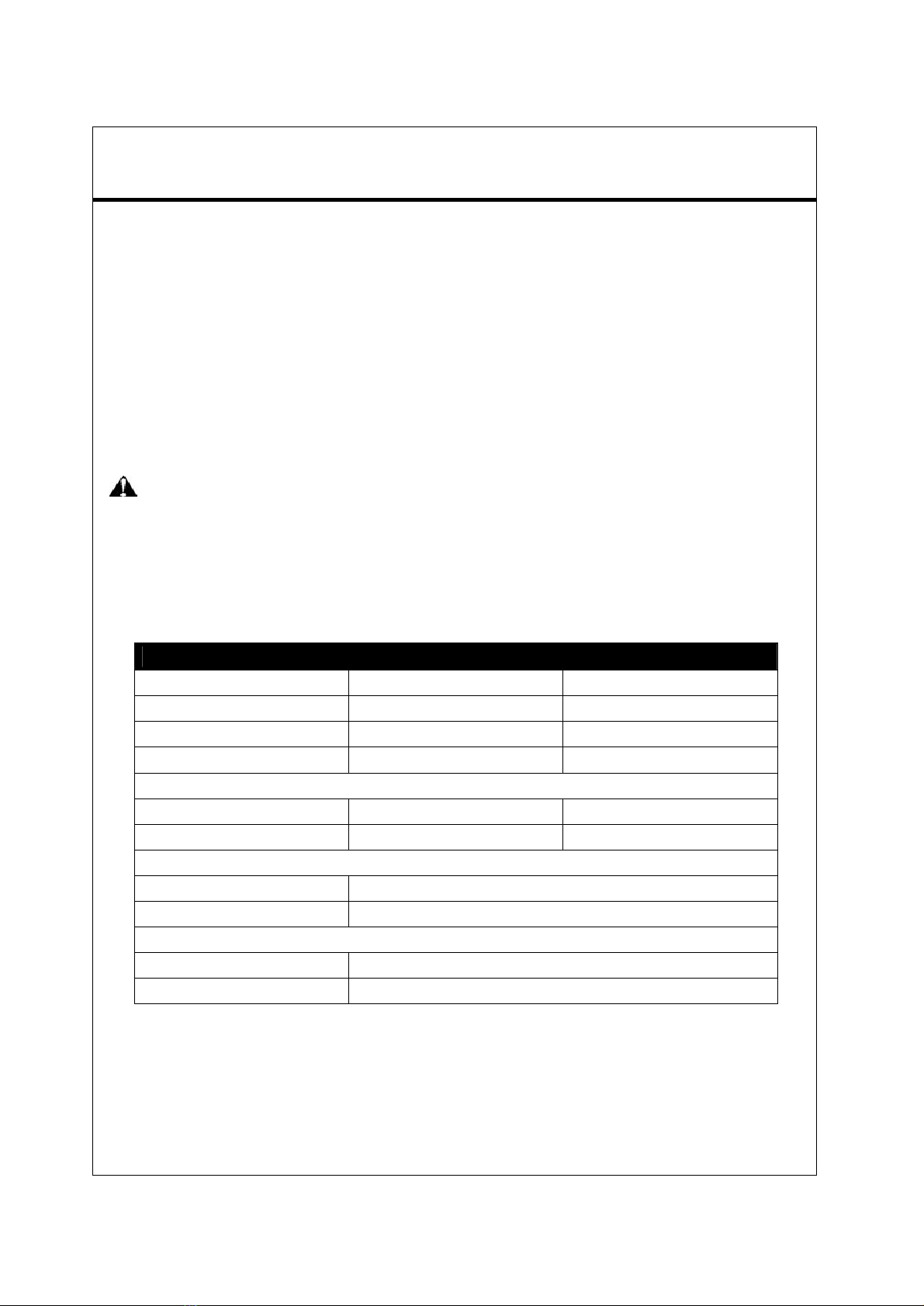
PRODUCTSPECIFICATIONS
MODEL NO. ADI10
Input Rating 10,000 BTU/Hr 10,000 BTU/Hr
Gas Type NaturalLP/Propane
IgnitionElectronic Piezo ElectronicPiezo
Manifold Pressure4 in. W.C. 9in. W.C.
Inlet Gas Pressure(*For purposes of input adjustment)
Maximum 10.5 in. 14 in.
Minimum*5 in. 11 in.
Dimensions, inches (H x W x D)
Heater27.7 in. x 16 in.x 11.7in.
Carton29.6 in. X 18.3 in. X13.5 in.
Weight, lbs
Stove 77
Shipping86
3
IMPORTANTSAFETY INFORMATION
IMPORTANT: Read this owner’s manual carefully andcompletely before trying to assemble, operate,
or service this heater.Improperuse ofthis heater can cause serious injuryor death from burns,fire,
explosion, electrical shock, and carbon monoxide poisoning.
Onlya qualified installer, service agent, or local gas supplier may installand service andservice this
product.
WARNING: Do not store or use gasoline or other flammable vapors or liquids in the vicinity ofthis
or any other appliance.
CARBON MONOXIDE POISONING: Early signs of carbon monoxide poisoning resemble the flu with
headaches, dizziness, ornausea. If you have these signs, the heater maynot be working properly. Get fresh
air immediately!Have heaterserviced. Some people are more affected by carbon monoxide than
others.These include pregnant women,people withheart,orlung disease,people who are anemic, those
under the influence of alcohol, and those living in high altitudes.
NATURAL AND PROPANE/LP GAS: Naturaland Propane/LP gases are odorless. An odor-making agentis
added to the gas.The odorhelps you detect a gas leak. However, the odor added to the gas can fade.Gas
may be present even though no odor exists. Make certain you read and understand all warnings. Keep this
manual forreference. It is your guide to operation of this heater.
Make certain you read and understand allwarnings. Keep thismanualfor reference. It is your guide to safe
and proper operation of this heater safely.
WARNING: Any change to thisfireplace or its controls can be dangerous.
WARNING: Do notallowfans to blow directly into the heater.Avoid any drafts that alter burner flame
patterns including ceiling fans.Altered burnerpatterns can cause sooting.
WARNING: Do notuse a blower insert, heat exchanger insert, orother accessory notapproved foruse
with this heater.
Due to high temperatures, the appliance should be located out of traffic and away from furniture and draperies.
Do not place clothing or other flammable material on or near the appliance. Never place any objects in the
heater. Heater becomes very hot when running. Keep children and adults away from hotsurfaces to avoid
burns or clothing ignition. Heater will remain hot for a time after shutdown. Allow surfaces to cool before
touching. Carefully supervise young childrenwhentheyare in the roomwith heater.
You must operate this heater with the heater screen in place. Make sure heaterscreen is in place before
runningheater.
Keep the heater area clear and free from combustible materials,gasoline,and other flammable vaporsand
liquids.

4
1.Do not place Propane/LPsupply tank(s) inside anystructure.Place Propane/LP supply tank(s)outdoors.
2.Thisheater should not be installed ina bedroom or bathroom.
3.Do not use this heater as awood-burning heater. Use only the logs provided with the heater.
4.Do not add extra logs or ornaments such as pine cones,vermiculite, orrock wool. Using these added items
can cause sooting. Do not add lava rock around base. Rock and debris couldfall into the control area of
heater. After servicing, always replace screen before operating heater.
5.Make sure the heater screen is in place before running the heater.
6.Thisheater is designed to be smokeless. If logs everappear to smoke, turn offheaterand callaqualified
serviceperson. Note: During initial operation,slight smoking could occur due to log curing and the heater
burning manufacturing residues.
7.To prevent the creation ofsoot,follow the instructions in Cleaningand Maintenance (page 19).
8.Before using furniturepolish,wax, carpet cleaner,or similar products, turn heater off. Ifheated,the vapors
fromthese products maycreate a white powderresidue within burner box or on adjacent wallsor furniture.
9.Thisheater needs fresh air ventilation to run properly. This heaterhas an Oxygen Depletion Sensing (ODS)
safetyshutoff system.The ODSshuts down the heater if not enough fresh air is available.See Airfor
Combustion and Ventilation,pages 7 through 9.If heater keeps shutting off, see Troubleshooting, pages20
through 22.
10. Do not run heater:
lWhereflammable liquids orvapors are used orstored.
lUnder dusty conditions.
11. Do not use this heater to cook food or burn paper or otherobjects.
12. Do not use this heater if any parthas been underwater.Immediately calla qualified service technician to
inspect the room heaterand replace anypart of the control system and any gascontrol which has been
underwater.
13. Turnoff and unplug heater and let coolbefore servicing. Only a qualifiedservice person should service and
repair heater.
14. Operating heater above elevations of 4,500 feetcould cause pilotoutage.
15. Do not operate heater if any log is broken. Do notoperate heater if any log is chipped (dime-sized or larger).
16. To prevent performance problems,do notuse a propane/LP fuel tank of less than 100 lbs capacity.
QUALIFIED INSTALLING AGENCY
Installation and replacement ofgas piping, gas utilization equipment oraccessories and repair and
servicing of equipment shall be performed only by a qualified agency.The term “qualified agency”means
any individual, firm, corporation,or company that either in person or through a representative is engaged
in and is responsible for:
a) installing, testing, or replacing gaspiping or
b) Connection, installing,testing, repairing, or servicing equipment; thatis experienced in such work;that is
familiar with all precautions required; and thathas complied with all the requirement ofthe authority
having jurisdiction.
5
PRODUCTFEATURES
SAFETY PILOT
This heaterhas a pilot with an Oxygen Depletion Sensing (ODS) safety shutoff system. The ODS/pilotis
arequired feature for vent-free room heaters. The ODS/pilotshuts offthe heater if there is not enough
fresh air.
DUALFUEL CAPABLE
Your Fireplaceis equipped to operate on eitherPropane or Natural gas. The fireplace is shipped fromthe
factory ready for Propane connection. The fireplace can easily be changed to Natural gasby having your
qualified installerfollowthe instructions on page 14 and the markings on the fireplace.
State of Massachusetts: The installationmustbe made by a licensed plumber orgas fitter inthe
Commonwealth of Massachusetts. Sellers of unvented propane ornatural gas-fired supplemental room
heaters shall provide to each purchaser a copy of 527 CMR 30 upon sale of the unit.
In the State ofMassachusetts, unvented propane ornatural gas-fired space heaters shall be prohibited in
bedrooms and bathrooms.
LOCAL CODES
Install and use heater withcare.Follow all local codes. Inthe absenceof local codes, use the latest
edition of the nation al fuel gas code, ANSI Z 223.1, also known as NFPA 54*.
*Available from:
American National Standardslnstitute, lnc.
1430 Broadway
New York, NY10018
National Fire Protection Association, lnc.
1Batterymarch Park
Quincy, MA02269
This heater is designed for vent-free operation. State and localcodes insome areas prohibitthe use of
vent-free heaters.
In the State ofMassachusetts the gas cock must be a T-handle type. The State of Massachusetts
requires that a flexible appliance connector cannot exceed three feet in length.
6
UNPACKING
1.Removetop innerpack.
2.Tilt carton so that heater is upright.
3.Removeprotective side packaging.
4.Slide heaterout of carton.
5.Removeprotective plastic wrap.
6.Hold the screen lift and pull forward.
7.Removelog setby cutting plastic ties.
8.Carefully unwrap log.
9.Check for any shipping damage.If heater or logs are damaged, promptly inform dealer where you bought
heater.
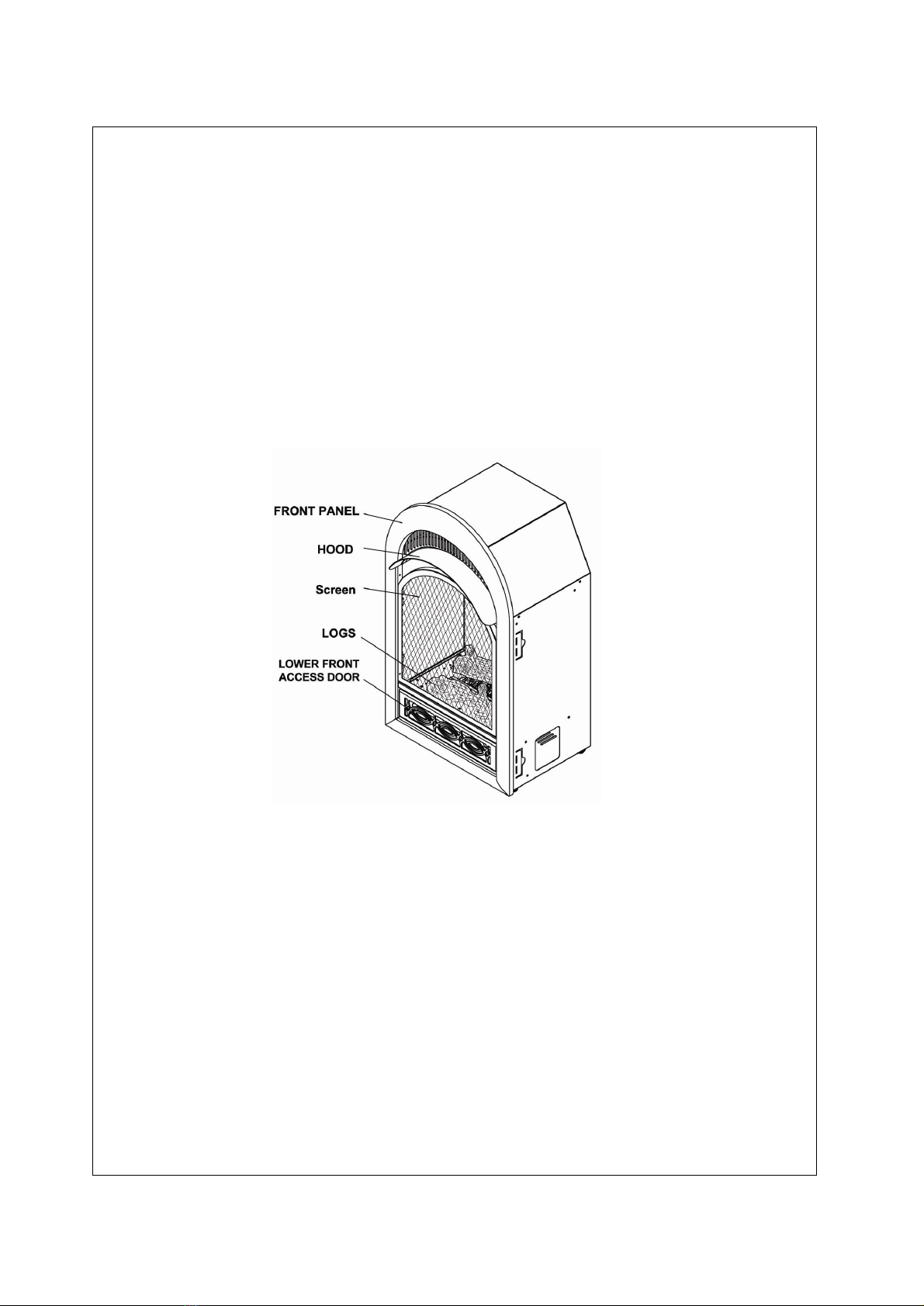
PRODUCT IDENTIFICATION
Figure 1 Vent Free LP/NG Gas Fireplace
WATERVAPOR: A BY-PRODUCT OFUNVENTEDROOM HEATERS
Water vaporisa by-product of gas combustion. An unvented room heater produces approximately one (1)
ounce (30ml)of water forevery1,000 BTU’s(.3KW’s) of gas input per hour.
Unvented room heaters are recommended as a supplementalheater (for a room),rather than a primary
heat source (for an entire house). In most supplemental heat applications, the water vapor does not create
aproblem. In most applications,the watervapor enhances the lowhumidity atmosphere experienced during
cold weather. The following steps will help insure that water vapor does notbecome a problem.
1.Be sure the heater is sized properly for the application,including adequate combustion airand
circulation air.
2.Ifthere is high humidity, the dehumidifier may be used to help lowerthe water vaporcontent ofthe air.
3. Do not use an unvented room heater as the primaryheat source.

7
AIR FORCOMBUSTION AND VENTILATION
WARNING: This heater shall not be installed in a confined space or unusually tight construction
unless provisions are provided foradequate combustion and ventilation air.Read the following
instructions to insure proper fresh air for this and other fuel-burning appliances in your home.
PRODUCING ADEQUATEVENTILATION
The following are excerpts from National FuelGas Code, NFPA54/ ANSI Z 223.1,Section 5.3, Airfor
Combustion and Ventilation.
All spaces in homes fall into one of the three following ventilation classifications:
1.Unusually Tight Construction
2.Unconfined Space
3.Confined Space
The informationon pages 7 through 9 will help youclassify your space and provide adequate ventilation.
Confined and Unconfined Space
The National Fuel Gas Code, ANSI Z223.1 defines a confined space as a space whose volume is less than 50
cubic feetper 1,000 BTU per hour(4.8 cubic meters per kw) ofthe aggregate input rating ofall appliances
installed in that space and an unconfining space as a space whose volume is not less than 50 cubic feet per
1,000 BTU per hour (4.8 cubic meters per kw) ofthe aggregate input rating ofall appliances installed in that
space. Roomscommunicating directly with the space in which the appliances are installed*,through openings
not furnished with doors, are considered a part of the unconfined space.
This heatershallnot be installed ina confined space or unusually tight construction unless provisions are
provided for adequate combustion and ventilation air.
* Adjoining rooms are communicating only if there are doorlesspassageways or ventilation grills
between them.
Unusually Tight Construction
The air that leaks around doorsand windowsmay provide enough fresh air for combustion and ventilation.
However, in buildingsof unusually tight construction,you must provide additional fresh air.
Unusually tightconstruction is defined as constructionwhere:
a) walls and ceilings exposed to the outside atmosphere have a continuous water vaporretarder with a
rating of one perm (6×10-11kg perpa-sec-m2) or less with openings gasketed orsealed and
b) weather stripping has been added on windows that can be opened and on doors and
c) caulking orsealants are applied to areas such as jointsaround window and door frames, between sole
plates and floors, between wall-ceiling joints, between wall panels, atpenetrations for plumbing,electrical,
and gas lines, and at other openings.
If yourhome meets all of the three criteria above, you mustprovide additional fresh air.See Ventilation Air
From Outdoors(page 9).Ifyour home does not meet all of the three criteria above, proceed to Determining
Fresh-AirFlow For Heater Location:

8
DETERMININGFRESH-AIR FLOW FOR HEATERLOCATION
Determining ifYou Have aConfined or Unconfined Space
Use this worksheet to determine if you have a confined or unconfined space.
Space: Includes the room in which you will install heaterplus any adjoining rooms with doorless
passageways or ventilation grillsbetween the rooms.
1.Determine the volumeofthe space Length ×Width ×Height=cu.ft. (volume of space)
Example: Space size 20 ft.(length) ×16 ft.(width) ×8 ft. (ceiling height)= 2560 cu.ft.(volumeof
space)
If additionalventilation to adjoining room is suppliedwith grills oropenings, add the volume of these rooms
to the total volume of the space.
2.Divide the space volume by 50 cubic feet to determine the maximum BTU/hr the space can support.
(volume of space) ÷50 cu. ft. = (Maximum BTU/hr the space can support)
Example: 2560 cu.ft. (volume of space) ÷50 cu.ft.= 51.2 or51,200(maximum BTU/hrthe space can support)
Add the BTU/hr of allfuel burning appliances in the space.
Vent-free heater BTU/hr
Gas water heater*BTU/hr
Gas furnace BTU/hr Example:
Vented gas heaterBTU/hr Gas water heater 30,000 BTU/hr
Gas heaterlogs BTU/hr Vent-free heater + 26,000 BTU/hr
Othergas appliances* + BTU/hr Total = 56,000 BTU/hr
Total =________________BTU/hr
*Do not include direct-vent gas appliances. Direct-vent draws combustion airfrom the outdoorsand vents to
the outdoors.
4.Compare the maximum BTU/hr that the space can supportwiththe actual amount of BTU/hr used.
BTU/hr (maximumthe space can support)
BTU/hr (actual amount of Btu/Hrused)
Example: 51,200 BTU/hr(maximumthe space can support)
56,000 BTU/hr(actual amount of Btu/Hr used)
The space in the above example is a confined space because the actual BTU/hr used ismore than the
maximum BTU/hr the space can support. You must provide additionalfresh air. Your options are as follows:
a) Reworkworksheet, adding the space of an adjoining room. Ifthe extra space provides an unconfined
space, remove door to adjoining roomor add ventilation grills between rooms.See “Ventilation Airfrom
Outdoors,”page 9.
b) Vent room directlyto the outdoors. See “Ventilation Air from Outdoors,”page 9.
c) Installa lowerBTU/hr heater, iflowerBTU/hrsize makes room unconfined. Ifthe actual BTU/hr used is
lessthan the maximum BTU/hr the space can support, the space is an unconfined space. You willneed
no additional fresh air ventilation.
WARNING: If the area in which the heater may be operated is smallerthan that defined as an unconfined
space or if the building is of unusually tightconstruction, provide adequate combustionand ventilationair by
one of the methods described in the National Fuel Gas Code, ANSI Z223.1/NFPA 54,Air forCombustion and
Ventilation, or applicable localcodes.”

9
Ventilation Air From lnsideBuilding
This fresh air would come from an adjoining
Unconfined space. When ventilating to an
adjoining unconfined space,you mustprovide
two permanentopenings: one within 12" of the
ceiling and one within12" ofthe flooron the
wall connectingthe two spaces (see options 1
and 2, Figure 2). You can also remove door
into adjoining room (see option 3, Figure 2).
Follow the National Fuel Gas Code. NFPA54/
ANSI Z223.1. Air for Combustion and
Ventilation for requiredsize of ventilation
grills orducts.
Ventilation Air From Outdoors
Provide extra fresh airby using ventilation grills
or ducts. You must provide two permanent
openings: one within 12" of the ceiling and one
within 12" ofthe floor.Connect these items
directlyto the outdoors or spacesopen to the
outdoors.These spaces include attics and
crawl spaces. Follow the NationalFuelGas
Code,NFPA 54/ ANSI Z223.1, Section 5.3, Air
forCombustion and Ventilation for required
size of ventilation grills or ducts.
IMPORTANT: Do not provide openings for
inlet oroutlet air into attic if attic has a
thermostat-controlled power vent. Heated
air entering the attic will activate the power
vent. Rework worksheet, adding the space
ofthe Adjoining unconfinedspace. The
combined spaces must have enough fresh
air to supply all appliances in both spaces.
Figure 3 Ventilation Air from Outdoors
Figure 2 Ventilation Air from inside

10
INSTALLATION
NOTICE: This heaterisintended for use as supplementalheat.Use this heater along with your primary
heatingsystem. Do not install thisheater asyour primary heat source. Ifyou have a centralheating
system, you may run system's circulating blower while using the heater. This willhelp circulate the heat
throughout the house.
WARNING: A qualified technician person must installthe heater.Follow all local codes.
WARNING: Neverinstallthe heater.
·in a bedroom or bathroom
·in a recreational vehicle
·where curtains, furniture,clothing, or otherflammable objects are less than 42 inches
fromthe front,top,or sides of the heater
·in high traffic areas
·in windy or drafty areas
CAUTION: Thisheater creates warm air currents. These currents move heatto wall surfaces next to
heater. Installing heater nextto vinyl or cloth wallcoverings or operating heaterwhere impurities(such as
tobacco smoke, aromaticcandles, cleaningfluids, oilor kerosene lamps,etc.) in the air exist, may discolor
walls.
WARNING: Maintainthe minimum clearances. Ifyou can, provide greater clearances from floor, ceiling,and
adjoining side and back walls.
IMPORTANT: Vent-free heaters add moisture to the air. Although thisis beneficial, installing heater in rooms
withoutenough ventilation air may cause mildew to form from too much moisture.See Air forCombustion and
Ventilation, pages 7 through 9.
CHECK GASTYPE
Use only the type ofgas indicated on the plate.Ifyour gas supply cannot meetthat requirement, do not install
heater.
CLEARANCESTO COMBUSTIBLES
Carefully follow the instructions below.This fireplace is a freestanding unit designed to setdirectly on the floor
or on a mantel base.
NOTE: When heater is installed directly on carpeting, tile orother combustible material, other than wood
flooring,the heater must be installed on a metal or wood panelextendingthe full width and depth ofthe heater.
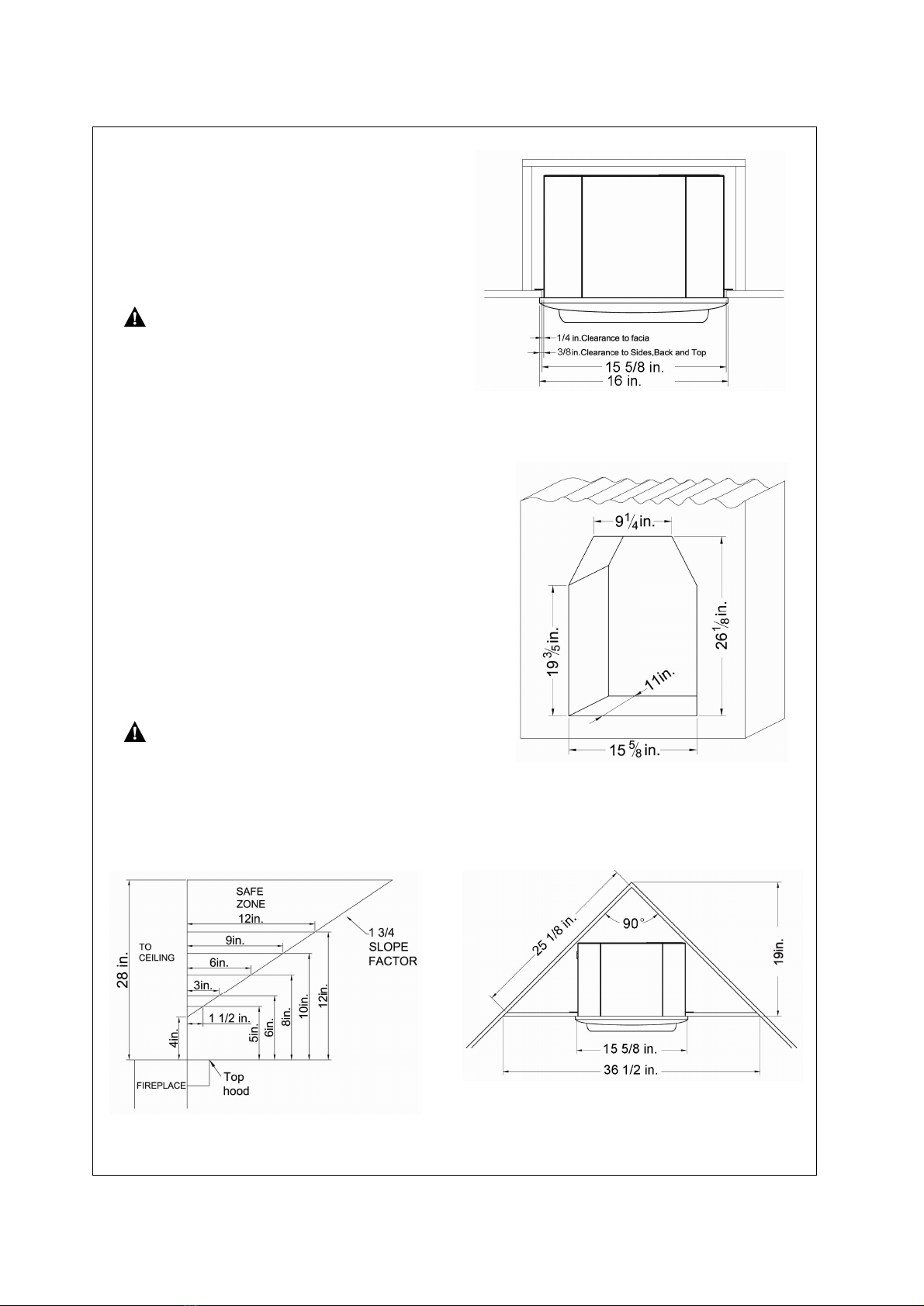
IMPORTANT: You must maintain minimumwall and ceiling clearancesduring installation. The minimum
clearances are shown in Figure 4, page 10.Measure fromoutermostpointoffireplace.
Minimum Wall and Ceiling Clearances
(see Figure 4)
A.Clearances from outermost point of fireplace
to any combustible side wallshould not be less
than 8 inches.
B.Clearances from the fireplace to the ceiling
should notbe less than 28 inches.
Figure 4 Minimum Clearance to Wall and Ceiling
11
BUILT-IN FIREPLACE INSTALLATION
Built-in installation of this fireplace involves
installingfireplace into aframed-in enclosure.
This makes the front of the fireplace flush
with wall. If installing abuilt-in mantel above
the fireplace, you mustfollow the clearances
shown in Figure 5. Follow theinstructions
below to installthe fireplace inthis manner.
NOTICE: Surface temperatures of
adjacentwallsand mantelsbecome hot
during operation. Walls and mantels
above the firebox may become hotto the
touch. If installed properly, these temperatures
meet the requirement of the national
product standard. Follow allminimum
clearances shown in thismanual.See Figure 4
and Figure 8.
1.Frame in rough opening.Use dimensions
shown in Figure 6 for the rough opening.
If installing in acorner, use dimensions
shown in Figure 7 for the rough opening.
The height is19 in., which is the same as
the wallopening above.
2.Carefully set fireplace in front of rough
opening with back of fireplace inside wall
opening.
3.Attach gas line to fireplace gas regulator.
See "Connecting to Gas Supply," page 12.
4.Check all gas connections forleaks. See
Checking Gas Connections, page 15.
IMPORTANT: Whenfinishing your
firebox,Combustible materials such as wall
board, gypsum board, sheet rock, drywall,
plywood, etc, must have ½-in.clearance to
the sides and top of the firebox. Combustible
materials should never overlap the firebox
front facing.
Figure 5 Clearanceto Combustibles
g
Figure 6 - Rough Opening for Installing inWall
Figure 7 - Rough Opening for Installing in Corner
Figure 8-Mantel andCeilingClearances

12
CONNECTINGTO GAS SUPPLY
WARNING: A qualified technicianmust connect heaterto gas supply. Follow all localcodes.
CAUTION: Never connect heater directly to the gas supply.This heater requires an external regulator (not
supplied). The external regulator between the gas supplyand heater must be installed.
INSTALLATIONITEMSNEEDED
Before installing heater, make sure you have the items listed below.
·piping (check local codes)
·sealant(resistant to propane/LPgas)
·equipment shutoff valve*
·test gauge connection**
·sediment trap
·tee joint
·pipe wrench
·FlexibleGas hose (check local code)
lACSA design-certified equipment shutoffvalve with 1/8in. NPT tap is an acceptable alternative to test
gauge connection.Purchase the optionalCSAdesign-certified equipment shutoffvalve from yourdealer.
WARNING: Neverconnect heaterto private (non-utility) gas wells. This gas is commonly known as
wellhead gas. The installer must supply an external regulator.The external regulatorwill reduce incoming
gas pressure. You mustreduce incoming gas pressure to between 11 and 14 inches of water column for
propane and between 5 and 10.5 inches of water column for natural gas. If you do not reduce incoming
gas pressure, heaterregulator damage could occur. Install external regulatorwith
Figure 9 -Gas Regulator Location and Gas Line
Access Into Fireplace Cabinet
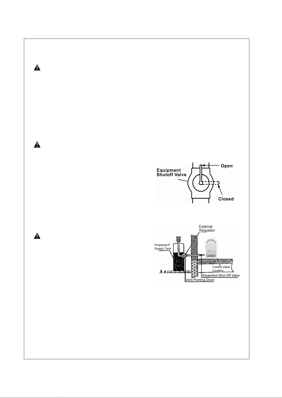
Figure 10 External Regulator with
Vent Pointing Down

13
INSTALLATION CONTINUED
The installer must supply an external regulator.The external regulatorwill reduce incoming gas pressure. You must
reduce incoming gas pressure to between 11 and 14 inches ofwater column for propane and between5 and 10.5
inches of watercolumn for natural gas. Ifyou do not reduce incoming pressure, heater regulator damage could
occur.
Install external regulatorwith the vent pointing down asshown in Figure 11.Pointing the vent down protects
it fromfreezing rain or sleet.
CAUTION: Use onlynew black iron or steel pipe. Internally-tinned copper tubing may be used in certain areas.
Check your local codes. Use pipe of 1/2" diameteror greater to allow proper gas volume to heater. If pipe istoo
small, a loss of pressure will occur. Installation must include an equipment shutoff valve, union, and plugged1/8"
NPT tap.Locate NPTtap within reach for test gauge hook up. NPT tap must be upstream from heater(see
Figure 11).
* Purchase the optional CSAdesign-certified equipment shutoffvalve from your dealer.See Accessories.
** Minimum inlet pressure for purpose ofinput adjustment.
IMPORTANT: Install equipment shutoff valve in an accessible location.The equipment shutoff valve is for turning on
or shutting off the gas to the appliance.Apply pipe joint sealant lightlyto male threads. This willprevent excess
sealantfromgoing into pipe.Excess sealantin pipe could resultin clogged heater valves.
CAUTION: Use pipe joint sealant thatis resistantto gas (PROPANEorNG).We recommend that you install a
sedimenttrap ina supply line as shown in Figure 11. Locate sedimenttrap where itis within reach for cleaning
and notlikely to freeze. Install in the piping system between fuel supply and heater. Asediment trap traps
moisture and contaminants. This keeps themfrom going into heater controls.If sedimenttrap is not installed or is
installedincorrectly, heater may not run properly.
CAUTION: Avoid damage to regulator.Hold gasregulatorwith wrench when connecting into gas piping and/or
fittings. NG Models:5in. to 10.5 in. W.C.Gas supplier provide external regulator for natural gas.
Figure 11 Gas Connection
14
Figure
12
Figure
13
Figure
1
4
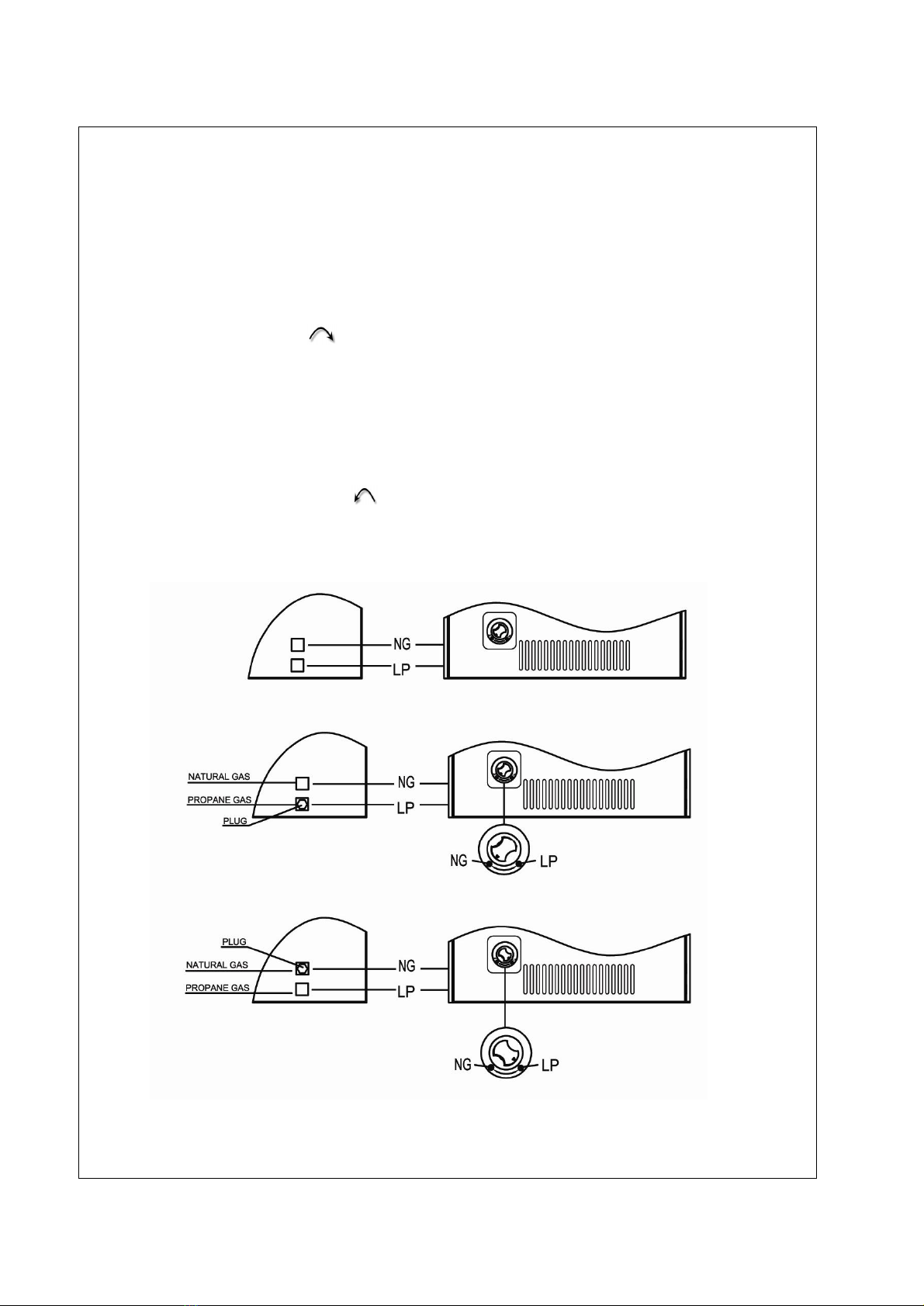
CAUTION: Two gaslineinstallations at the same time is forbidden. Do not open cover while
the heater is running.
Heater is pre-set at factory for propane gas,no changes are required for connecting to propane.Only
a qualified installer or service technician can perform gas selection and connecting to gas supply.
For changing from propane tonaturalgas supply
1. Remove bottom screwfrom cover plate, see figure 12,and rotate to expose gas selection valve.
2. For NATURAL GAS, press in knob using aflat screw driver with a blade the thickness of a quarter
and turn knob clockwise until the knob locks into the NG position (see figure 13).Selection
valve must be locked into eitherthe NG position. Do not operate heaterbetween locked positions!
3. Rotate and close cover over gas selection valve and reinstall screw.
4. Remove hex plug (with wrench provided from natural gas inlet of regulator and installinto LP inlet
of regulator, usethread sealant to assure there are no leaks).
For changing from natural gas supply to propane gas supply:
1. Remove bottom screwfrom cover plate, see figure 12,and rotate to expose gas selection valve.
2. For propane gas, press in knob using a flatscrew driver with a blade the thickness of a quarter
and turn knob counterclockwise until the knob locks into the LP position (see figure 14).
Selection valve must be locked into the LP position.
3. Rotate and close cover over gas selection valve and reinstall screw.
Remove hex plug frompropane gas inlet of regulatorand installinto NG inlet of regulator,use
thread sealantto assure there are no leaks.
15
CHECKING GAS CONNECTIONS
WARNING: Test all gas piping and connections for leaks afterinstalling or servicing.Correctall leaks
immediately.
Pressure Testing Gas Supply PipingSystem
Pressures In Excess Of ½PSIG(3.5kPa)
1. Disconnect heaterwith itsappliancemain gas valve (controlvalve)and equipment shutoff valve from gas
supplypiping system.Pressures in excess of 1/2 psig will damage heater regulator.
2. Cap off open end of gas pipe where equipment shutoffvalve was connected.
3. Pressurize supply piping system by eitherusing compressed air oropening gas supply tank valve.
4. Check alljoints ofgas supply piping system. Applymixture of liquid soap and water to gas joints. Bubbles
forming show a leak.
5. Correctall leaks immediately.
6. Reconnect heater and equipment shutoffvalve to gas supply. Check reconnected fittings for leaks.
WARNING: Never use an open flame to check for a leak. Apply a mixture ofliquid soap and water to all
joints. Bubbles forming showa leak.Correctall leaks immediately.
Pressure Testing HeaterGas Connections
1. Open equipment shutoffvalve (see Figure 15).
2. Open gas supply tank valve.
3. Make sure control knob of heater is in the OFF position.
4. Check alljoints from equipment shutoff valve to control
valve (Figure 15). Apply mixture ofliquid soap and water
to gas joints.Bubbles formingshow a leak.
5. Correctall leaks immediately.
6. Lightheater (see Operation Heater, page 17).Check all
otherinternaljoints forleaks.
7. Turn off heater(see Operation of Turn-Off ,page 18).
CAUTION: Make sure external regulator has been
installed between gas supply and heater. See guidelines
under Connecting to Gas Supply (page 12).
TestPressures EqualTo or Less Than 1/2 PSIG(3.5 kPa)
1. Close equipment shutoffvalve (see Figure 15).
2. Pressurize supply piping system by eitherusing
compressed air or opening gassupply tank valve.
3. Check alljoints from gasmeter to equipmentshutoff valve (see
Figure 16). Apply mixture ofliquid soap and water to gas joints.
Bubbles forming show a leak.
4. Correctall leaks immediately.
Figure 15 - EquipmentShutoff Valve
Figure 16 -Checking Gas Joint
16
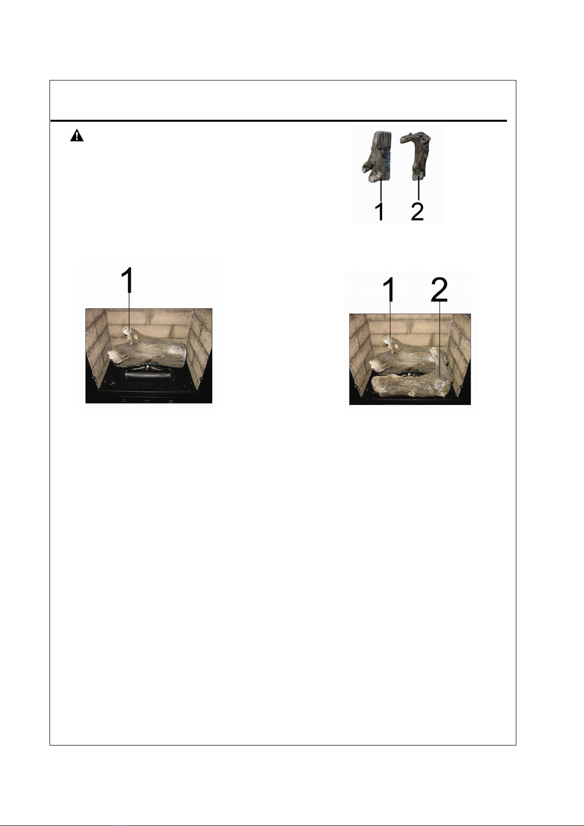
INSTALLING LOGS
WARNING: Failure to position the parts in
accordance with these diagrams or failure to use only
partsmay resultin property damage or personal injury.
CAUTION: Afterinstallationand periodically
thereafter,check to ensure that no flame comes in
contact with any log. With the heater set to High (5),
check to see ifflames contact any log. If so,reposition
logs according to the log installation instructions in
this manual.Flames contacting logswillcreatesoot.
Alllogs
STEP 1: Install log 1on the rear plate as shown.
STEP2: Installlog 2on the frontplate.
17
OPERATING HEATER
WARNING: If you do not followthese instructions exactly,a fire or explosion may result causing property
damage, personal injuryor loss oflife.
NOTICE: During initial operation ofnew heater, burninglogs will give off a paper-burning smell. Orange
flame will alsobe present. Open a windowto vent smell.This will lastonly few hours.
CAUTION: Do not trytoadjust heating levels by using the equipmentshutoff valve.
A. Thisappliance has a pilot which must be lightedby the electronic ignitor.When lighting the pilot, follow
these instructions exactly.
B.BEFORELIGHTING smellall around the appliance area for gas. Be sure tosmellnext to the floor because
some gas isheavierthan air and willsettle on the floor.
WHAT TO DO IF YOUSMELL GAS
•Do not try to light any appliance.
•Do not touchany electrical switch; do notuse any phone in your building.
•Immediately call your gassupplierfrom a neighbor’sphone. Follow thegas supplier’sinstructions.
•If you cannot reach your gas supplier, call the firedepartment
C. Use only your hand to push control. Neveruse tools. If the appliance does not operate,don’ttry to repairit.
Call a qualified service technician orgas supplier. Forced or attempted repair may result in fire or explosion.
D. Do not use this applianceif any parthas been underwater.Immediately calla qualified service technician to
inspectthe appliance and toreplace any partofthe control system and any gas control, whichhas been under
water.
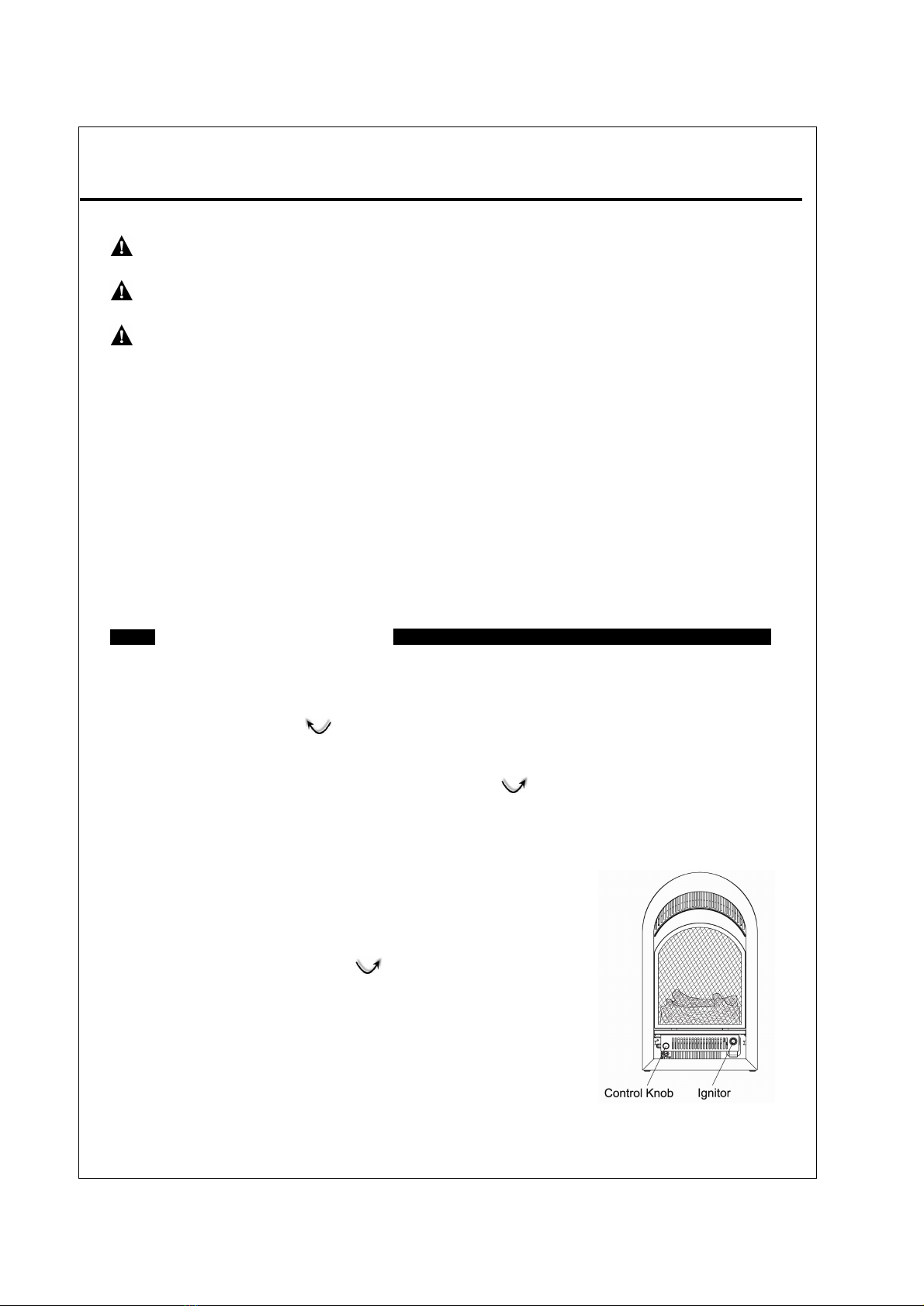
1. Unscrew ignitorcap and installa AAAbattery with the + pointing out.Replace cap.
2. STOP!Read the safety information on page 17.
3. Make sure manual shutoffvalve is fully open.
4. Turn control knob clockwise to the OFF position.
5. Wait five(5)minutes to clear out any gas. Then smellfor gasaround heaterand near floor. Ifyou smellgas,
STOP!Follow "B"in the safetyinformation on Warnings plate. Ifyou don'tsmell gas,go to the next step.
6. Push in gas controlknob slightly and turn counterclockwise to the PILOT position. Keep control
knob pressed in for five (5) seconds. Note: You may be running this heater for the first time after hooking up
to gas supply. If so, the control knob may need to be pressed in for 30 seconds. This will allow air to escape
from the gas system.
Ifcontrol knob does not pop up when released, contact a qualifiedservice person orgas supplierfor repairs.
7. With control knob pushed in,press and hold ignitorbutton,located
on the otherside of front panel. This will lightthe pilot.If needed,
keep ignitor button pressed until pilotlights.
8. Continue pushing the controlknob in for afurther 60 seconds to allow
thermocouple to warmup. Release the control knob.
9. Turn control knob counterclockwise to the ON position.
10. Ifthe heater willnot operate, follow the instructions "To Turn Off
Gas To Appliance"and call your service
technician or gas supplier.
LIGHTING INSTRUCTIONS
Figure 17 Control Knob Position
18
Shutting Off Heater
1. Turn control knob clockwise to the OFF position.
2. Turn offall electricpower (ifused) to the appliance if service is to be performed.
Shutting offBurner Only (pilot stays lit)
Turn control knob clockwise to the PILOT position.
(Match light)
1. Remove screen by lifting and pulling forward.
2. Followsteps 1 through 5 under Lighting Instructions.
3. With Control Knob in PILOT position, strike match, and hold near pilot. Press in ControlKnob; pilot should
light.
4. Keep ControlKnob pressed in for 30 seconds afterlighting pilot. After30 seconds, release ControlKnob.
5. Make sure the heater screen isin place before operating heater.
INSPECTING BURNERS
Check pilot flame pattern and burner flame patterns often.
PILOTFLAMEPATTERN
1. Turn control knob to pilot position
2. Inspect pilot flame and refer to Figure 18 and 19.
·Figure 18shows a correct pilot flame pattern.
·Figure 19 shows an incorrectpilot flame pattern. The incorrect pilot flame is not touching the thermocouple.
·This will cause the thermocouple to cool. When the thermocouple cools,the heaterwill shutdown.
·If the pilot flame isincorrect, as shown in Figure 19. Turnheater off (see To Turn OffGas to Appliance) See
troubleshooting, page 20-22.
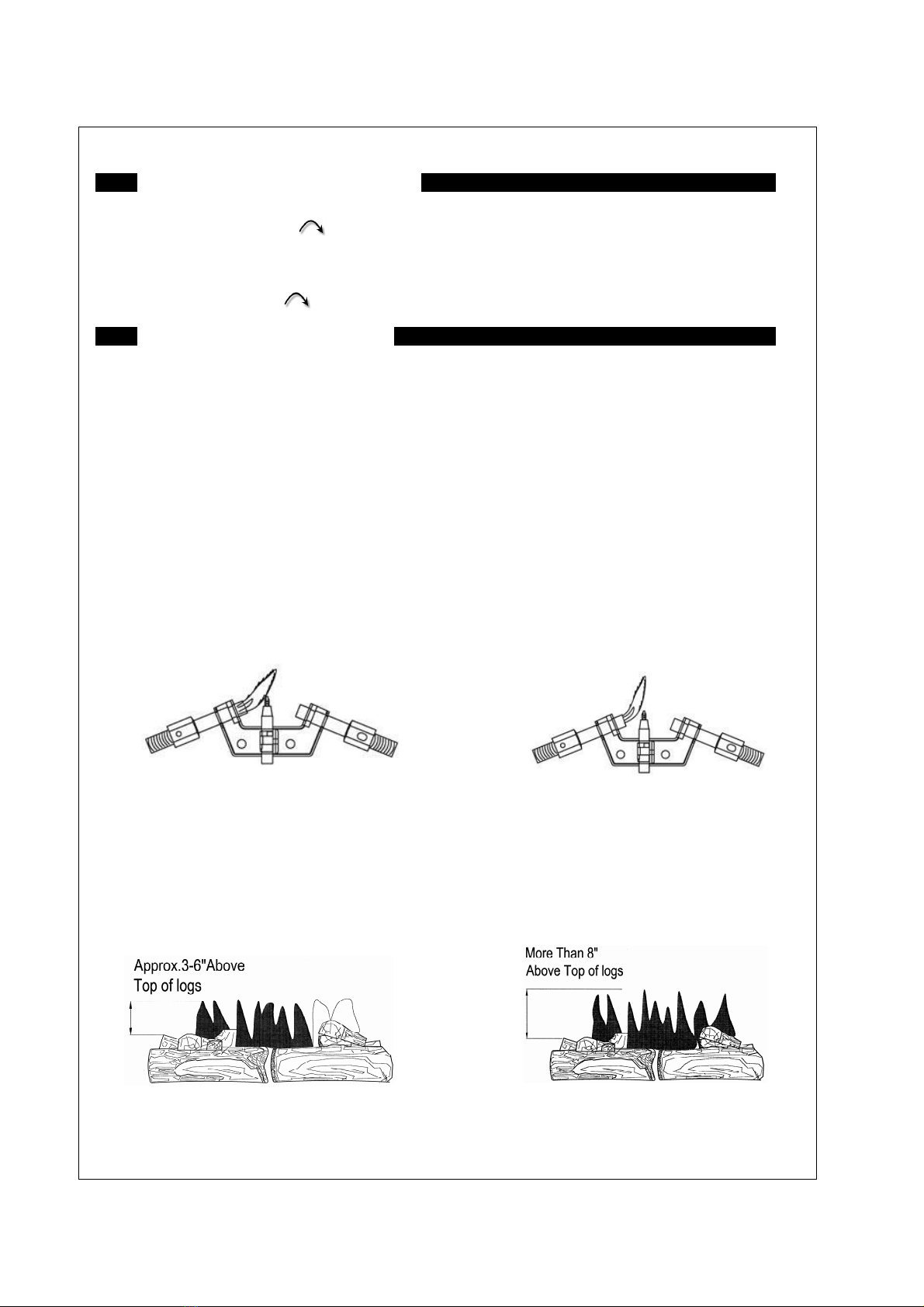
BURNERFLAMEPATTERN
·Figure 20 shows a correct burner flame pattern.
·Figure 21 shows an incorrectburner flame pattern.
If burner flame is incorrect: as shown in Figure 21.Turn heater off (see To Turn Off Gasto Appliance) see
Troubleshooting, Page 20-22.
MANUAL LIGHTING PROCEDURE
TO TURNOFF GASTO APPLIANCE
Figure 18 -Correct Pilot Flame Pattern
Figure 19 -Incorrect Pilot Flame Pattern
Figure 21 IncorrectBurner Flame Pattern
Figure 20 Correct Burner Flame Pattern

19
CLEANING AND MAINTENANCE
WARNING: Failure to keep primary air openings of burnersclean may result in sooting and property damage.
CAUTION: You must keep control areas, burner, and circulating airpassageways of heater clean. Inspect
these areas of heater before each use. Have heater inspected yearly by a qualified service person. Heater may
need more frequentcleaning due to excessive lintfrom carpeting, bedding material,pet hair, etc.
MAINBURNER
Periodically inspect all burnerflame holes with the heater running. All slotted burner flame holes should be open
with yellow flame present.All round burner flame holes should be open with a smallblue flame Present. Some
burnerflame holes may become blocked by debris or rust, with no flame present.Ifso,turn off heaterand let
cool, eitherremove blockage or replace burner. Blocked burner flame holes willcreate soot.
CLEANING BURNER INJECTOR HOLDER AND PILOT AIRINLET HOLE
We recommend that you clean the unit every three months or after 2500 hoursofoperation. We also recommend
that you keep the burner tube and pilot assemblyclean and free of dust and dirt. To clean these parts we
recommend using compressed air no greaterthan 30 PSI.You can use a vacuumcleanerin the blow position. If
using compressed air in a can, please follow the directions on the can. If you don't follow directions on the can,
you could damage the pilotassembly.
1. Shutoffthe unit, including the pilot. Allow the unit to cool
forat least thirty minutes.
2. Inspect burner, pilot and primary air inlet holes on injector
holder fordust and dirt (see Figure 22).
3. Blow air through the ports/slots and holesin the burner.
4. Check the injector holder located at the end ofthe burner
tube again. Remove any large particles of dust, dirt, lint,
or pethairwith a soft cloth or vacuum cleaner nozzle.
5. Blow air into the primary airholes on the injector holder.
6. In case any large clumps ofdust have now beenpushed
into the burner. Repeat steps 3 and 4. Clean the pilot
assembly also.
CLEANING ODS/PILOT
Use a vacuum cleaner, pressurized air,or a small, soft
bristledbrush to clean.
A yellow tip on the pilot flame indicates dust and dirt in
the pilot assembly. There is a small pilot airinlet hole
about two inches from where the pilot flame comes out
of the pilot assembly (see Figure 23). With the unit off,
lightlyblowair through the airinlethole. You may blow
through a drinking strawif compressed air is not available.
CABINET
Air Passageways
•Use a vacuum cleaner or pressurized airto clean the cabinetto remove dust.
LOGS
•If you remove logs forcleaning, referto Installing Logs (page 16) forproperlog placements.
•Replace logs ifbroken or chipped (dime-sized or larger).
Use a soft, clean cloth
dampened with mild soap
and waterto clean airinlet
holes.
Figure 22 Injector holder on Outlet
Burner Tube
Figure 23 Pilot Air Inlet Hole
20
TROUBLESHOOTING
WARNING: If you smellgas
·Shutoff gas supply.
·Do not try to light any appliance.
·Do not touch any electrical switch; do notuse any phone in your building.
·Immediately call your gas supplierfrom a neighbor’sphone. Followthe gas supplier’sinstructions.
·If you cannot reach your gassupplier,call the firedepartment.
IMPORTANT: Operating heater where impurities in air exist may create odors.
Cleaning supplies, paint,paint remover, cigarette smoke,cements and glues, new carpet or textiles,etc.,
create fumes. These fumes may mix with combustion air and create odors.
WARNING: Make sure thatpower is turned offbefore proceeding.
WARNING: Turn offand let cool before servicing. Onlya qualified service person should service and
repair heater.
CAUTION: Neveruse a wire, needle, orsimilar object to clean ODS/pilot. This can damage ODS/pilotunit.
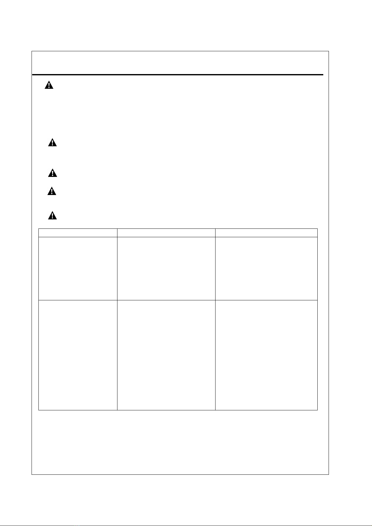
OBSERVED PROBLEM POSSIBLE CAUSE REMEDY
Whenignitor button is
pressedin, thereis no spark
at ODS/pilot
1.Ignitoris positioned wrong.
2.Ignitorelectrode is broken.
3.Ignitorelectrode is notconnected
to ignitor cable.
4.Ignitorcable ispinched or wet.
5.Damaged ignitorcable.
6.Bad piezo ignitor.
7.Low battery.
1. Replaceelectrode.
2. Replaceelectrode.
3. Reconnect ignitor cable.
4. Free ignitor cable if pinched by any
metal or tubing.Keep ignitorcable
dry.
5. Replaceignitor cable.
6.Replacepiezo ignitor.
7.Replacebattery.
When ignitor button is
pressed in, there is a spark at
ODS/pilot but no pilot flame
present.
1.Gassupply isturned off or
equipmentshutoff valve is closed.
2.Controlknob not fully pressed in
while pressing ignitor button.
3.Air in gaslines (new installation or
recent gas interruption).
4.ODS/pilot isclogged.
5.Incorrect inlet gas pressure or inlet
regulator is damaged.
6.Depleted gassupply
1. Turn on gas supply or open
equipment shutoff valve.
2. Fully press in control knob while
pressing ignitor button.
3. Continue holding down control
knob for 30 seconds to remove air.
Repeatigniting operation until air
is removed.
4. Clean ODS/pilot(see Cleaning
and Maintenance Page 19) or
replace ODS/pilot assembly.
5. Checkinletgas pressure or
replace inlet gas regulator.
6. Contact localpropane/LPGas
Company
Table of contents
Other Hearth Sense Fireplace Accessories manuals

Popular Fireplace Accessories manuals by other brands


Petromax
Petromax px-wbrk9 user manual

Stove Guard
Stove Guard 2010 Installation & operating manual

Napoleon
Napoleon GS67-1 installation instructions

Hearth and Home Technologies
Hearth and Home Technologies Contour36 installation instructions

Dimplex
Dimplex SEP-BW-4217-FB install guide

Extraflame
Extraflame Comfort P70 instruction manual

Dimplex
Dimplex ROCKLIN EMP-OSTN-26 install guide

Lennox Hearth Products
Lennox Hearth Products BV4000C manual

Dogberry Collections
Dogberry Collections DOGB001 Installation instructions manual

Solas
Solas Helios Pulse user manual

pleasant hearth
pleasant hearth FA013TA manual

Napoleon
Napoleon PRPH35 installation instructions