HearthRite HVF2R18N-2 Manual

VENT-FREE
Models:
This appliance
is equipped
for natural or
propane gas. Field
conversion is not
permitted.
WARNING
GAS LOG HEATER
User’s Manual and Operating
Instructions
INSTALLER: Leave this manual with the appliance.
CONSUMER: Retain this manual for future reference.
HR2008VFL
•Do not store or use gasoline or other flammable vapors and liquids in the vicinity of this or
any other appliance.
• WHAT TO DO IF YOU SMELL GAS:
• Do not try to light any appliance.
•Do not touch any electrical switch; do not use any phone in your building.
•Immediately call your gas supplier from a neighbor’s phone. Follow the gas supplier’s instructions.
•If you cannot reach your gas supplier, call the fire department.
•Installation and service must be performed by a qualified installer, service agency, or the gas supplier.
WARNING: If the information in this manual is not followed exactly, a fire or
explosion may result causing property damage, personal injury, or loss of life.
This appliance may be installed in an aftermarket, permanently located, manufactured (mobile)
home, where not prohibited by local codes. This appliance is only for use with the type gas
indicated on the rating plate. This appliance is not convertible for use with other gases.
This is an unvented gas-fired heater. It uses air (oxygen) from the room in which it is installed. Provisions
for adequate combustion and ventilation air must be provided. Refer to the AIR FOR COMBUSTION
AND VENTILATION section on page 8 of this manual.
!CAUTION —FOR YOUR SAFETY
HVF2R24N-2 / HVF2R24P-2
HVF2R18N-2 / HVF2R18P-2
ANS Z21.11.2-2019
ANS Z21.60-2017 • CSA 2.26-2017
MC NO. 274387

2
Vent-Free Gas Log Heater User Manual
Table of Contents
Specifications
Specifications ........................................................................................................................................................................................ 2
Safety Information ..............................................................................................................................................................................3
Product Identification ........................................................................................................................................................................ 5
General Preparation ........................................................................................................................................................................... 6
Preparing for Installation ..................................................................................................................................................................7
Installation ............................................................................................................................................................................................10
Log Placement .....................................................................................................................................................................................20
Operation ..............................................................................................................................................................................................22
Wiring .....................................................................................................................................................................................................21
Care and Maintenance .....................................................................................................................................................................25
Troubleshooting Guide ....................................................................................................................................................................27
Parts List .................................................................................................................................................................................................30
Limited Warranty ................................................................................................................................................................................31
Read this entire manual and all operating instructions before operating this heater.
WARNING
IMPORTANT: Read all instructions and warnings carefully before starting installation. Failure to follow
these instructions may result in possible injury to persons or a fire hazard and will void the warranty.
Only a qualified installer, service agent, or local gas supplier may install and service this product.

3
Vent-Free Gas Log Heater User Manual
Safety Information
CARBON MONOXIDE POISONING: Early signs of carbon monoxide poisoning
resemble the flu with headaches, dizziness, or nausea. If you have these signs, the log
set may not be working properly. Get fresh air immediately, and have the log set serviced. Some people
are more aected by carbon monoxide than others: pregnant women, people with heart or lung disease,
people who are anemic, those under the influence of alcohol, and those living in high altitudes.
WARNING
NATURAL AND PROPANE GAS: Natural and propane gases are odorless. An odor-making agent is added
to the gas. The odor helps you detect a gas leak. However, the odor added to the gas can fade. Gas may
be present even though no odor exists. Make certain you read and understand all warnings. Keep this
manual for reference. It is your guide to operating this heater safely.
WARNING:
•Due to high temperatures, the heater should be located out of traffic and away from furniture and draperies.
•The heater becomes very hot when operating. Children and adults should be alerted to the hazard of
high surface temperature and should stay away to avoid burns or clothing ignition. The heater will re-
main hot for a time after shuto.
• Allow surfaces to cool before touching.
• Young children should be carefully supervised when they are in the same room with the appliance.
•Do not place clothing or other flammable material on or near the heater. Never place any objects in the
heater.
•Installation and repair should be done by a qualified service person. The heater should be inspected
before use and at least annually by a professional service person. More frequent cleaning may be
required due to excessive lint from carpeting, bedding material, etc. It is imperative that control
compartments, burners, and circulating air passageways of the heater be kept clean.
•Any safety screen or guard removed for servicing an appliance must be replaced prior to operating the heater.
• Any change to this heater or its controls can be dangerous.
• Do not use any accessories not approved for use with this heater.
•Keep the heater area clear and free from combustible materials, gasoline, and other flammable vapors
and liquids.
• This appliance is intended for supplemental heating.
FIRE, EXPOLSION, AND ASPHYXIATION HAZARD
WARNING
Improper adjustment, alteration, service, maintenance, or installation of this heater or its controls
can cause death or serious injury.
Read the following instructions and precautions in User's Information Manual provided with this
heater.
W
ARNING:
CALIFORNIA PROPOSITION 65: Fuels used in gas-fired heaters and the products of
combustion of such fuels contain chemicals known to the state of California to cause cancer, birth defects,
or other reproductive harm. This product contains chemicals, including lead and lead compounds, known
to the state of California to cause cancer, birth defects, or other reproductive harm. For more information
go to www.P65Warnings.ca.gov. Wash hands after handling.

4
Vent-Free Gas Log Heater User Manual
Safety Information (cont.)
WARNING:
• This heater must only be used with the type of gas indicated on the rating label. This heater is not
convertible for use with other gases.
• Do not place propane supply tank(s) inside any structure. Place propane supply tank(s) outdoors.
• If you smell gas, do the following:
• Shut off the gas supply;
• Do not try to light any appliance;
• Do not touch any electrical switch, and do not use any phone in your building;
• Immediately call your gas supplier from a neighbor’s phone. Follow the gas supplier’s instructions. If
you cannot reach your gas supplier, contact the fire department.
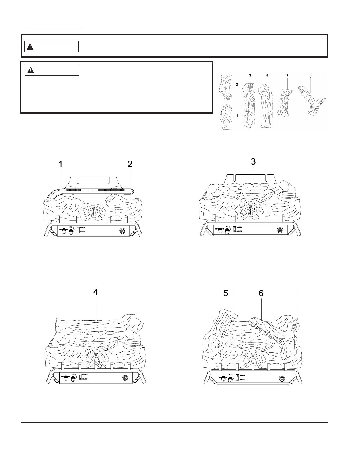
• Do not use this heater to burn real wood. Use only the logs provided with the heater.
• Do not add extra logs or ornaments such as pine cones or rock wool. These items may cause sooting.
• Never place objects in the fireplace or the logs.
• This heater is designed to be smokeless. If the logs ever appear to smoke, turn off the heater and call a
qualified service person. NOTE: When first using the heater, slight smoking may result from log curing
and manufacturing residues.
• To prevent the creation of soot, follow the instructions in CARE AND MAINTENANCE on pages 24 and 25.
•Before using furniture polish, wax, carpet cleaner, or similar products, turn the heater o. If heated, the vapors
from these products may create a white powder residue within the burner box or on adjacent walls or furniture.
• This heater must never be installed in a bedroom or bathroom.
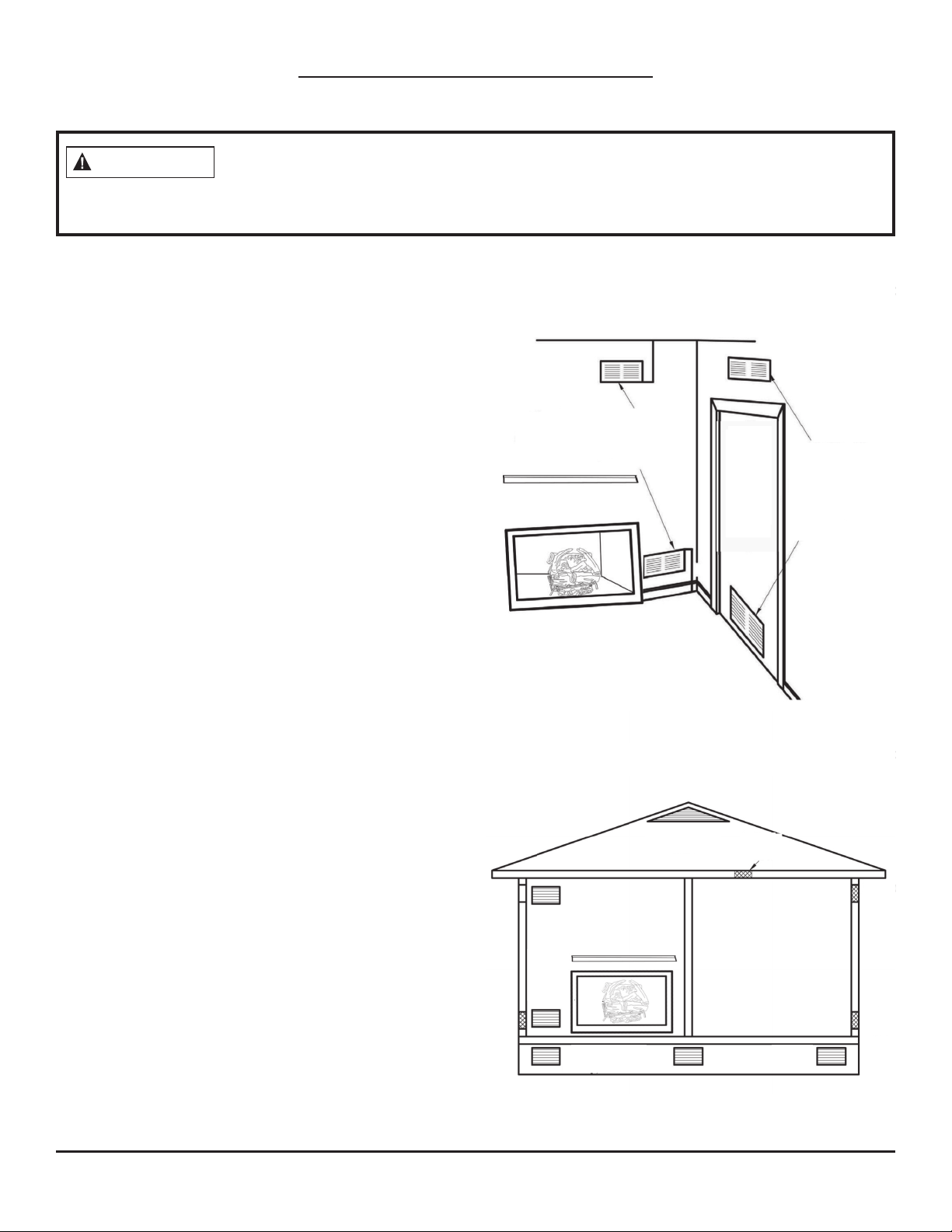
• This heater needs fresh air ventilation to run properly and safely. This heater has an Oxygen Depletion
Sensing (ODS) safety shutoff system. The ODS shuts down the heater if not enough fresh air is available.
See AIR FOR COMBUSTION AND VENTILATION, page 7. If the heater keeps shutting o, see the
TROUBLESHOOTING GUIDE, page 26.
• Do not run the heater:
• Where flammable liquids or vapors are used or stored;
• Under dusty conditions.
• Do not use this heater to cook food or burn anything.
•Do not use the heater if any part has been under water. Before use, call a qualified service technician to
inspect the heater and replace any part of the control system and/or gas control that has been under water.
• Turn off and let the heater cool before servicing. Only a qualified service person should service and repair
the heater.
• Operating the heater above elevations of 4,500 feet may cause pilot outage.
•Do not operate the heater if a log is broken. Do not operate the heater if a log is chipped (dime-sized or larger).
• To prevent performance problems, do not use propane fuel tank of less than 100 lb. capacity.
• Provide adequate clearances around air openings.
• A fireplace screen must be in place when the heater is operating. Unless other provisions for
combustion air are provided, the screen shall have an opening(s) for introduction of combustion air.
QUALIFIED INSTALLING AGENCY: Only a qualified agency should install and replace gas piping, gas
utilization equipment, or accessories, and/or repair and service such equipment. “Qualified agency” means
any entity that either in person or through a representative is engaged in and is responsible for:
• Installing, testing, or replacing gas piping; or
•Connecting, installing, testing, repairing, or servicing equipment; is experienced in such work; is familiar with
all precautions required; and has complied with all the requirements of the authority having jurisdiction.

5
Vent-Free Gas Log Heater User Manual
Product Identification
SAFETY PILOT
This heater has a pilot with an Oxygen Depletion Sensing (ODS) safety shutoff system. The ODS/pilot shuts
off the heater if there is not enough fresh air and cuts off the main burner gas in the event of flame out.
REMOTE HEATCONTROL
Some remote heat controls have thermostat settings that automatically cycles the burner on and off to maintain
a desired set room temperature. When used as a vented decorative appliance, use of the thermostat function is
prohibited. Operate manually only.
Safety Information (cont.)
Make Owners Aware of Proper Log Set Operation Log Placement
Properly installed and properly maintained log sets do not deposit soot on the logs. If users see soot on a
log, they should call for service. Do not continue to operate the log set.

6
Vent-Free Gas Log Heater User Manual
General Preparation
LOCAL CODES
Install and use the heater with care. Follow all local codes. The installation must conform with local codes or,
In the absence of local codes, with the latest edition of The National Fuel Gas Code, ANS Z223.1/NFPA 54*.
This heater is designed for vent-free operation. State and local codes in some areas prohibit the use of vent-
free heaters.
*Available from:
American National Standard Institute, Inc.
1430 Broadway
New York, NY 10018
National Fire Protection Association, Inc.
1 Batterymarch Park
Quincy, MA 02269-9101
This log set has been tested and approved to ANS Z21.11.2-2016 standard for Unvented Heaters and can be
operated with the flue damper closed. State and local codes in some areas prohibit the use of vent-free heaters.
State of Massachusetts: The installation must be made by a licensed plumber or gas fitter in the
Commonwealth of Massachusetts. Sellers of unvented propane or natural gas-fired supplemental
room heaters shall provide to each purchaser a copy of 527 CMR 30 upon sale of the unit.
In the State of Massachusetts, unvented propane or natural gas-fired space heaters are prohibited
in bedrooms and bathrooms.
In the State of Massachusetts the gas cock must be a T-handle type. The State of
Massachusetts requires that a flexible appliance connector cannot exceed three feet
in length.
The installation of appliances designed for manufactured home (U.S. only) or mobile home installation
must conform with the Standard CAN/CSA Z240 MH, Mobile Housing, in Canada, or with the Manufactured
Home Construction and Safety Standard, Title 24 CFR, Part 3280, in the United States, or when such a
standard is not applicable, ANS/NCSBCS A225.1/NFPA 501A, Manufactured Home Installations Standard.

7
Vent-Free Gas Log Heater User Manual
Preparing for Installation
WATER VAPOR IS A BY-PRODUCT OF UNVENTED ROOM HEATERS
Gas combustion creates water vapor as a by-product. Unvented room heaters create about one (1) ounce (30
ml) of water for every 1,000 BTUs (0.3 kW) of gas input per hour. An unvented room heater is recommended
as a supplemental heat source for a single room rather than as a primary heat source for an entire house. The
water vapor does not typically create a problem. In most cases, the water vapor enhances the low humidity
conditions that are typical of cold weather.
Keep these points in mind so that the water vapor does not create a problem:
•The heater must be the proper size for the application. Provide adequate combustion air and circulation air.
• In humid environments, use a dehumidifier to help lower the amount of water vapor in the air.
• Do not use an unvented room heater as your primary heat source.
AIR FOR COMBUSTION AND VENTILATION
This heater shall not be installed in a room or space unless the required volume of indoor combustion air is
provided by the method described in the National Fuel Gas Code, ANS Z223.1/NFPA 54, the International Fuel
Gas Code, or applicable local codes.
PRODUCING ADEQUATE VENTILATION
Spaces in homes can be divided into these ventilation classifications:
•Unusually Tight Construction
• Unconfined Space
• Confined Space
The information on pages 7–9 will help you classify your space and provide adequate ventilation.
Confined and Unconfined Space:
A confined space has a volume less than 50 cu. ft. per 1,000 BTU/hr (4.8 m3 per kW) of the total input rating
of all appliances installed in that space. An unconfined space has a volume not less than 50 cu. ft. per
1,000 BTU/hr (4.8 m3 per kW) of the total input rating of all appliances installed in that space. Rooms that
are directly connected to the space in which the appliances are installed*, through openings that do not
have doors, are considered a part of the unconfined space.
Do not install this heater in a confined space or unusually tight construction unless you provide provisions
for adequate combustion and ventilation air.
*Adjoining rooms are directly connected only if there are doorless passageways or ventilation grills between them.
Unusually Tight Construction:
Doors and windows may leak air that provides enough fresh air for combustion and ventilation. However,
you must provide additional fresh air in buildings of unusually tight construction. Unusually tight
construction is defined as construction that meets the following criteria:
A. Walls and ceilings exposed to the outside atmosphere have a continuous water vapor retarder with a
rating of one perm or less with openings that are gasketed or sealed.
B. Doors and windows that can be opened have weather stripping.
C. Caulking or sealants are applied to areas such as joints around window and door frames; between sole
plates and floors; between wall-ceiling joints; between wall panels; at penetrations for plumbing,
electrical, and gas lines; and at other openings.
If your residence meets all the above criteria, additional fresh air must be provided. See VENTILATION AIR
FROM OUTDOORS on page 9 for more information. If your residence does not meet those three criteria,
continue to DETERMINING FRESH-AIR FLOW FOR THE HEATER LOCATION.

8
Vent-Free Gas Log Heater User Manual
Preparing for Installation (cont.)
DETERMINING FRESH-AIR FLOW FOR THE HEATER LOCATION
Determining if You Have a Confined or Unconfined Space:
Use the below information to determine if you have a confined or unconfined space. Your space includes
the room in which you will install the heater plus any other rooms that are directly connected and have
doorless passageways or ventilation grills between the rooms.
1. Determine the volume of the space. Length × Width × Height = cu. ft. (volume of space)
• Example: 20 ft. (length) × 16 ft. (width) × 8 ft. (ceiling height) = 2560 cu. ft. (volume of space)
If additional ventilation to adjoining room(s) is supplied with grills or openings, add the volume of these
rooms to the total volume of your space.
2. Divide the space’s volume by 50 cu. ft. to determine the maximum BTU/hr the space can support.
_______ (volume of space) ÷ 50 cu. ft. = (maximum BTU/hr the space can support)
•Example: 2560 cu. ft. (volume of space) ÷ 50 cu. ft. = 51.2 or 51,200 (maximum BTU/hr the space can support)
3. Add the BTU/hr of all fuel burning appliances in the space:
Vent-free heater _________ BTU/hr
Gas water heater* ________BTU/hr
Gas furnace _____________BTU/hr
Vented gas heater ________BTU/hr Example:
Gas heater logs __________BTU/hr Gas water heater 30,000 BTU/hr
Other gas appliances*+ ____BTU/hr Vent-free heater + 26,000 BTU/hr
Total = ____BTU/hr Total = 56,000 BTU/hr
*Do not include direct-vent gas appliances. Direct-vent appliances draw combustion air from outdoors
and vent to the outdoors.
4. Compare the maximum BTU/hr the space can support with the actual amount of BTU/hr used:
_______ BTU/hr (maximum the space can support)
_______ BTU/hr (actual amount of BTU/hr used).
•Example : 51,200 BTU/hr (maximum the space can support) 56,000 BTU/hr (actual amount of BTU/hr used)
The space in the above example is a confined space because the actual BTU/hr used is more than the
maximum BTU/hr the space can support. You must provide additional fresh air. Your options are as follows:
A. Add the space of an adjoining room and rework the above information. If the extra space creates an
unconfined space, remove the door to the adjoining room or add ventilation grills between rooms.
See VENTILATION AIR FROM INSIDE A BUILDING, page 9.
B. Vent the room directly to the outdoors. See VENTILATION AIR FROM OUTDOORS, page 9.
C. Install a heater that uses less BTUs/hr if the lower BTUs/hr creates an unconfined space. If the actual BTU/
hr used is less than the maximum BTU/hr the space can support, the space is an unconfined space. In
this case, no additional fresh air ventilation is needed.

9
Vent-Free Gas Log Heater User’s Manual
Preparing for Installation (cont.)
If the area in where the heater operates does not meet the required volume for
indoor combustion air, you must provide combustion and ventilation air by one of the
methods described in the NATIONAL FUEL GAS CODE, ANSI Z223.1/NFPA 54, the INTERNATIONAL FUEL GAS
CODE, or applicable local codes.
WARNING
VENTILATIONAIRFROMINSIDEABUILDING
Fresh air comes from a connected unconfined space.
You must provide two permanent openings when
ventilating to a connected unconfined space, one of
which that’s within 12" of the wall that connects the
two spaces (see options 1 and 2, Fig. 1). You may also
remove the door into the adjoining room (see option 3,
Fig. 1). Follow the National Fuel Gas Code NFPA 54/ANS
Z223.1 for the required size of ventilation grills or ducts.
VENTILATION AIR FROM OUTDOORS
Extra fresh air is provided via ventilation grills or
ducts. You must provide two permanent openings:
one within 12" of the ceiling and one within 12" of
the floor. They must connect directly to the outdoors
or spaces that open to the outdoors. Such spaces
may include attics or crawl spaces. Follow the
National Fuel Gas Code NFPA 54/ANS Z223.1 for the
required size of ventilation grills or ducts.
IMPORTANT: Do not provide openings for inlet or
outlet air into an attic if the attic has a thermostat-
controlled power vent. The power vent will be
activated by heated air that enters the attic. You must
add the space of the connected unconfined space
and rework the information on page 8. The combined
spaces must have enough fresh air to supply all
appliances in both spaces.
12 in.
Ventilation Grills
Into adjoining Room
Option 2
Or
Remove
Door
Into
Adjoining
Room
Option 3
Ventilation
Grills
Into Adjoining
Room
Option 1
To
Attic
To
Crawl
Space
Outlet
Air
Ventilated
Crawl Space
Ventilated
Attic
Inlet Air
Inlet
Air
Outlet
Air
12 in.
Ventilation Grills
Into adjoining Room
Option 2
Or
Remove
Door
Into
Adjoining
Room
Option 3
Ventilation
Grills
Into Adjoining
Room
Option 1
To
Attic
To
Crawl
Space
Outlet
Air
Ventilated
Crawl Space
Ventilated
Attic
Inlet Air
Inlet
Air
Outlet
Air
Fig. 1—Ventilation Air from Inside a Building
Fig. 2—Ventilation Air from Outdoors

10
Vent-Free Gas Log Heater User Manual
Installation
Never install the heater in a bedroom or bathroom; in a recreational vehicle; where
curtains, furniture, clothing, or other flammable objects are less than 42" from the
front, top, or sides of the heater; in high traffic areas; or in windy or drafty areas.
WARNING
This heater creates warm air currents. These currents move heat to wall surfaces that
are next to the heater. Installing the heater next to vinyl or cloth wall coverings, or
operating the appliance where impurities in the air exist (tobacco smoke, aromatic candles, cleaning fluid ,
oil or kerosene lamps, etc.), may cause walls to discolor.
CAUTION
Any glass doors must be fully opened when you are operating the heater.
WARNING
Before installing in a solid fuel-burning fireplace, the chimney flue and firebox must be
flame patterns.
Do not use a blower insert, heat exchanger insert, or other accessory not approved for
use with this heater.
WARNING
This appliance is for installation only in a solid fuel- burning or UL 127 factory-built
fireplace or in a listed ventless firebox enclosure. It has been design certified for these
installations. Exception: DO NOT install this appliance in a factory-built fireplace that includes instructions
stating it has not been tested or should not be used with unvented gas logs.
WARNING
Do not burn solid fuels in your fireplace when this heater is also installed.
Outside air ducts and/or ash dumps in the fireplace must be permanently closed when
NOTICE: This heater is intended to be used as a supplemental heating source. Use this heater along with
your primary heating system. This heater must not be used as a primary heat source. If you have a central
heating system, you may run that system’s circulating blower while using this heater. This helps to circulate
the heat around your house.
WARNING
A qualified technician must install the heater. Follow all local codes.
WARNING
WARNING
Do not allow fans to blow directly into the fireplace. Avoid any drafts that alter burner
WARNING
this heater is installed.
WARNING
Creosote will soften when heated and can drop onto the logset causing odors and soot.
cleaned of soot, creosote, ashes, and loose paint by a qualified chimney cleaner.

11
Vent-Free Gas Log Heater User Manual
Installation (cont.)
IMPORTANT: Vent-free heaters add moisture to the air, which is beneficial. However, if this heater is installed
in areas without adequate ventilation, mildew may form from too much moisture in the air. See AIR FOR
COMBUSTION AND VENTILATION, pages 7 through 9.
CHECK GAS TYPE: Be sure your gas supply is right for your heater. If the supply is not correct, do not install
the heater. Contact the place where this heater was purchased for a heater appropriate for your gas supply.
NOTICE: State or local codes may only allow operation of this appliance in a vented configuration. Check
your state or local codes.
HEATER CLEARANCES
For convenience and efficiency, install the heater with these points in mind:
• Provide easy access for operation, inspection and service.
• Install the heater in the coldest part of the room.
If this heater is installed directly on carpeting, tile, or other combustible material, other than wood flooring,
the heater must be installed on a metal or wood panel that extends the heater’s full width and depth.
Minimum Clearances for Side Combustible Material, Side Wall, and Ceiling:
A. Clearances from the side of the heater cabinet to any combustible material and wall must follow the
specifications listed in the below table.
B. Clearances from the top of the heater opening to the ceiling must not be less than 36".
Log Sizing Requirements
Log Size Minimum Firebox Size
Height Depth Front Width Rear Width
18 in. 24 in 14 in. 28 in. 20 in.
24 in. 24 in. 14 in. 32 in. 22 in.
If you install the heater in a home garage, a.) ensure the heater pilot and burner are at
least 18" above the floor and, b.) locate the heater where moving vehicles will not hit it.
CAUTION
Maintain the minimum clearances. If possible, provide greater clearances from the
Minimum Fireplace Clearance to Combustible Materials
Log Size Side Wall Ceiling
18 in. 16 in. 36 in.
24 in. 16 in. 36 in.
Seal any fresh air vents or ash clean-out doors located on the floor or wall of the
fireplace with a heat-resistant sealant—this prevents drafting caused by pilot outage
or sooting. Do not seal the chimney flue damper.
WARNING
WARNING
floor, ceiling, and adjoining wall than required.

12
Vent-Free Gas Log Heater User Manual
Installation (cont.)
Minimum Noncombustible Material Clearance—If Not Using a Mantel:
You must have noncombustible material(s) such as slate, tile, or marble above the fireplace opening. These
materials must be at least 1/2" thick. If using sheet metal, you must have noncombustible material behind
it, such as a noncombustible fireplace hood accessory (see Fig. 4).
NOTICE: This heater may be used as a vented product. If doing so, you must always operate log set with chimney
flue damper open. If running log set with damper open, noncombustible material above fireplace opening is not
needed. See INSTALLING DAMPER CLAMP ACCESSORY FOR VENTED OPERATION, page 15. When used as a
vented decorative appliance, use of the thermostat function is prohibited—operate manually only.
Minimum Noncombustible Material Clearance—If Using a Mantel:
You must have noncombustible material(s) such as slate, tile, or marble at least 1/2" thick. If using sheet
metal, noncombustible material must be behind it. Noncombustible material must extend at least 12" up.
If noncombustible material is less than 12", a fireplace hood accessory must be installed. If
noncombustible material is more than 12", you may still require the hood accessory to deflect heat away
from mantel shelf. See Fig. 3 and 4 above for minimum clearance requirements.
IMPORTANT: If the minimum clearances are not met, you must operate the heater with the chimney flue
damper open. See INSTALLING DAMPER CLAMP ACCESSORY FOR VENTED OPERATION, page 15.
Heat Resistant
Material
Heat Resistant
Material
(A)
12" min.
Firebox
2 4 6 8 10 12 14 16 18
Inches
Firebox
Inches
Fig. 3—Minimum Clearance for Combustible to Wall Fig. 4—Heat Resistant Material (slate,
marble, tile, etc.) above Fireplace

13
Vent-Free Gas Log Heater User Manual
MANTEL CLEARANCES
In addition to meeting noncombustible material clearances, you must also meet required clearances between
the fireplace opening and mantel shelf. A fireplace hood is required if the below clearances are not met.
Determining Mantel Clearances:
If you meet the minimum clearance requirements between the mantel shelf and the top of the fireplace
opening, you do not require a fireplace hood (see Fig. 5).
Determining Minimum Mantel Clearance When Using a Hood:
If the minimum clearances in Fig. 6 are not met, you must use a hood. When using a hood there are still
certain minimum mantel clearances required, as shown in Fig. 6.
NOTICE: When operating the heater, the surface temperature of adjacent walls and mantels become hot.
Walls and mantels above the firebox may become too hot to touch. If installed properly, these temperatures
meet the requirement of the national product standard. Follow all minimum clearances shown in this manual.
NOTICE: If your installation does not meet the minimum clearances, you must only operate the heater with
the flue damper open, or you must raise the mantel to an adequate height.
Installation (cont.)
Noncombustible Material Installation Requirements
Noncombustible
Material Distance Requirements for Safe Installation
8" or more Noncombustible material is okay.
Less than 8"
Noncombustible material must be extended to at least 8". See between 8" and
12" on the previous page. If you cannot extend the material, the heater must be
operated with the flue damper open
Maximum
10" Combustible
Mantel
Minimum 20"
Maximum
10" C
ombustible
Mantel
Minimum
18"
Minimum
10"
Maximum
2-1/2"
4" Sheet
Metal Hood
Fig. 5—Closed Flue Mantel
Clearances without Hood
Fig. 6—Closed Flue Mantel
Clearances with Hood

14
Vent-Free Gas Log Heater User Manual
FLOOR CLEARANCES
In addition to meeting noncombustible material clearances, you must also meet required clearances between
fireplace opening and mantel shelf. A fireplace hood must be used if you do not meet the below clearances.
A. If installing the heater on floor level, you must maintain the minimum distance of 5" to combustibles (see
Fig. 7).
B. If combustible materials are less than 5" to the fireplace, you must install the heater at least 5" above the
combustible flooring (see Fig. 8).
Installation (cont.)
Combustible
Material
Non-Combustible
Material
5"
Min.
Fig. 7—Minimum Fireplace
Clearances if Installed at Floor Level
Combustible
Material
Hearth
5 in.
Min.
Fig. 8—Minimum Fireplace
Clearances above Combustible Flooring
Log Set Size
18" 24"
Chimney
Height*
(ft)
Minimum Opening**
(sq. in.)
625.7 33.8
823.7 31.2
10 21.7 28.7
15 19.9 26.1
20 18.5 23.7
30 16.9 21.6
Log Set Size
18" 24"
Chimney
Height*
(ft)
Minimum Opening**
(sq. in.)
10 16.6 22.1
15 12.6 17.3
20 10.8 14.5
25 9.6 12.6
30 9.1 11.3
35 8.0 10.8
40 7.5 10.2
For Masonry-Built Fireplaces Free
Opening Area of Chimney Damper
For Factory-Built Fireplaces Free
Opening Area of Chimney Damper
* Height is from hearth to hte top of the
chimney and the minimum height is 6 feet.
** Chart shows a minimum opening (sq. in.)
for a given height and input rate.
* Height is from hearth to the top of the
chimney and the minimum height is 10 feet.
** Chart shows a minimum opening (sq. in.)
for a given height and input rate.
WHEN USED AS A VENTED LOG SET

15
Vent-Free Gas Log Heater User Manual
Before beginning assembly or operation of this heater, ensure all parts are present. Check the parts against
the package contents list. If any part is missing or damaged, do not attempt to assemble, install, or operate
the heater. Contact customer service for replacement parts.
Estimated Assembly Time: 1 to 2 hours
Tools Required for Assembly (not included, unless otherwise stated):
Before installing the heater, ensure you have the following:
• Hardware package (included)
• Approved flexible gas hose if allowed by local codes
• Sealant (resistant to natural or propane gas)
• Electric drill with 3/16" drill bit
• Phillips screwdriver
• External regulator (supplied by installer if required)
• Piping (check local codes)
•Equipment shutoff valve
• Test gauge connection
• Sediment trap
• Tee joint
• Pipe wrench
•3/8" NPT to 3/8" flare fitting
Installation (cont.)
UNPACKING
1. Remove logs, grate, and burner base assembly from carton.
NOTE: Do not pick up the burner base assembly by the burners. This could damage heater. Only handle the
base assembly by its frame.
2. Remove all protective packaging used on the logs and heater.
3. Inspect the items for shipping damage. If you notice any damage, contact the dealer where the heater
was purchased.
Fig. 9—Attach Damper to Fireplace
Damper
Damper Clamp
Damper
“Opened
Position”
INSTALLING DAMPER CLAMP ACCESSORY FOR VENTED OPERATION
NOTE: When used as a vented heater, the heater must
be installed only in a solid-fuel burning fireplace with a
working flue constructed of noncombustible material.
You may use this heater as a vented product. When
used as a vented decorative appliance, use of the
thermostat function is prohibited—operate manually
only. There are three reasons for operating your heater
as a vented model:
1. The fireplace does not meet the clearance requirements
for vent-free operation.
2. State or local codes do not permit vent-free operation.
3. You prefer vented operation.
Any chimney damper must be fixed in a manner that will maintain the minimum permanent vent opening
at all times. Installing a damper clamp to prevent the damper from accidentally closing is recommended
(see Fig. 9).

16
Vent-Free Gas Log Heater User Manual
Installation (cont.)
CONNECTING TO A GAS SUPPLY
The installer must supply an external regulator for liquid propane. For natural gas, the gas supplier supplies
the external regulator. The external regulator reduces incoming gas pressure, and the pressure must be
reduced to between 11" and 14" of water column for propane and between 6" and 10.5" of water column
for natural gas. Heater regulator damage could occur if the pressure of the incoming gas is not reduced.
Install the external regulator with the vent pointing down as shown in Fig. 10. The purpose of pointing the
vent down is to protect it from freezing rain or sleet.
*The equipment shutoff valve can be purchased from your local home center store.
A qualified service technician must connect heater to gas supply. Follow all local codes.
WARNING
Never connect the heater directly to the gas supply. This heater requires an external
regulator (not supplied). The external regulator between the gas supply and heater
must be installed. Your gas supplier provides the external regulator for natural gas.
CAUTION
Never connect the heater to private/non-utility gas wells (commonly known as
wellhead gas).
WARNING
Equipment Shutoff Valve With
1/8" NPT Tap*
Approved
Flexible
Gas Line
or 1/2"
Black Pipe
3" Minimum
Sediment Trap
Propane From
External
Regulator (11"
W.C.** to 14" W.C.
Pressure)
Natural
From Gas Meter
Fig. 11—Gas Connection
External
Regulator
with Vent
Pointing
Down
Propane
Supply
Tank
Fig. 10—Regulator Conversion
IMPORTANT: Install equipment shutoff valve in an accessible location. The equipment shutoff valve is
for turning on or shutting off the gas to the heater. Apply pipe joint sealant lightly to the male threads.
This prevents excess sealant from going into the pipe. The heater valves may become clogged if excess
sealant gets into the pipes.
Use only new black iron or steel pipe. Internally tinned copper tubing may be used
in certain areas, depending on your local codes. Use pipe of 1/2" diameter or greater
to allow proper volume gas to heater. If the pipe is too small, loss of pressure will occur. Installation must
include an equipment shutoff valve, union, and plugged 1/8" NPT tap. The NPT tap must be located within
reach for the test gauge hook up and be upstream from heater (see Fig. 11).
CAUTION
Pipe Nipple Cap Tee Joint
(6" to 10.5" W.C.
Pressure)

17
Vent-Free Gas Log Heater User Manual
Installation (cont.)
Use pipe joint sealant that is resistant to gas (propane or NG). We recommend that you
install a sediment trap in a supply line, which traps moisture and contaminants. The
sediment trap should be located within reach for cleaning and where it is not likely to freeze. Install it in the
piping system between the fuel supply and heater. This keeps contaminants from getting into the heater
controls. The heater may not run properly if the sediment trap is not installed or is installed incorrectly.
CAUTION
Avoid damage to the regulator. Hold the gas regulator with a wrench when connecting
into gas piping and/or fittings. NG Models: 6" to 10.5 W.C. /11" to 14" W.C..
Your gas supplier provides an external regulator for natural gas.
CAUTION
INSTALLATION ITEMS NEEDED (NOT PROVIDED):
•8" Adjustable Wrench
•8" Pipe Wrench
• 3/8" Flexible Gas Line (24" Min.) or 1/2" Black Pipe
• 90 Deg. 3/8 NPT x 3/8" Flare Fitting or 3/8" Street Elbow
• Sealant (Resistant to natural or propane gas)
•Shutoff Valve
1. Depending on where your gas supply line is located, a variety of options are possible for routing the gas
connection lines. First, install the 3/8" fitting to the heater regulator using sealant. Direct the attachment
either left or right toward the gas supply line.
NOTICE: Most building codes do not permit concealed gas connections. Check your local building
code before using a flexible gas line for this installation.
2. Install the gas line to the 90 deg. fitting, and attach it to the shutoff valve (see Fig. 12 & 13). Depending on
your connection, it might be necessary to cut and access the hole in the side or bottom of the mantel cabinet.
3. Check all connections for gas leaks.
Fig. 12—Gas Inlet to Regulator Fig. 13—Attaching the Flexible Gas Line
to the Equipment Shutoff Valve
Flexible Gas Line or
Black Pipe to Heater
Cabinet Regulator
To Regulator
EQUIPMENT
SHUTOFF
VALVE
PROPANE
To External Regulator
NATURAL GAS
To Gas Supply

18
Vent-Free Gas Log Heater User Manual
Installation (cont.)
CHECKING GAS CONNECTIONS
Pressure Testing Gas Supply Piping System
Test Pressures in Excess Of 1/2 PSIG (3.5 kPa):
1. Disconnect the heater, including the main gas valve (control valve) and equipment shutoff valve, from
the gas supply piping system. Pressures greater than 1/2 PSIG will damage the regulator.
2. Cap off the open end of the gas pipe where the equipment shutoff valve was connected.
3. Open the gas supply tank valve or use compressed air to pressurize the supply piping system.
4. Check all joints of the gas supply piping system. Use a mixture of liquid soap and water in the gas joints
to check for leaks—bubbles may indicate a leak.
5. Immediately correct all leaks.
6. Reconnect the heater and equipment shutoff valve to gas supply. Check reconnected fittings or leaks.
Test Pressures Equal To or Less Than 1/2 PSIG (3.5 kPa):
1. Close the equipment shutoff valve (see Fig. 14).
2. Open the gas supply tank valve or use compressed air to pressurize the supply piping system.
3. Check all joints from the gas meter to the equipment shutoff valve (see Fig. 15.1 & 15.2).
4. Use a mixture of liquid soap and water in the gas joints to check for leaks—bubbles may indicate a leak.
5. Immediately correct all leaks.
Pressure Testing Heater Gas Connections:
1. Open the equipment shutoff valve (see Fig. 14).
2. Open the gas supply tank valve.
3. Ensure the control knob of the heater is in the OFF position.
4. Check all joints from the equipment shutoff valve to the control
valve (see Fig. 15.1 & 15.2). Use a mixture of liquid soap and water
in the gas joints to check for leaks—bubbles may indicate a leak.
5. Light the heater (see OPERATION, page 21-23). Check all other
internal joints for leaks.
6. Turn off the heater (see TO TURN OFF GAS TO THE HEATER, page 23).
After installing or servicing the heater, test all gas piping and connections for leaks.
Immediately correct all leaks.
WARNING
Never use an open flame to check for a leak. Apply a mixture of liquid soap and water
to all joints—bubbles may indicate a leak. Immediately correct all leaks.
WARNING
Equipment
Shuto
Valve
Open
Closed
Fig. 14—Equipment
Shutoff Valve
Equipment
Shuto
Valve Propane
Supply
Tank
Gas Control Valve
Fig. 15.1—Checking Gas Joints (Propane Only)
Gas Control Valve Equipment
Shutoff Valve
Gas Meter
Fig. 15.2—Checking Gas Joints (Natural Gas Only)

19
Vent-Free Gas Log Heater User Manual
Installation (cont.)
BEFORE INSTALLING THE HEATER
•Turn off the gas supply to the fireplace or firebox.
• Clean the fireplace floor and chimney before installing the heater. Seal any ash, and clean out doors to
protect the unit from down drafts.
MOUNTING PROCEDURE
• Place the grate/burner assembly into the firebox.
• Using the log set as a guide, drill four (4) 5/32" diameter holes approximately 1" deep into the floor of
the firebox.
• Anchor the grate/burner assembly to the floor using four (4) concrete attachment screws (not
included)(see Fig. 16).
Fig. 16—Mounting Locations
1/4" x 3/4" Concrete Hex Head
Flanged Attachment Screws

20
Vent-Free Gas Log Heater User Manual
Log Placement
Failure to position the parts in accordance with these diagrams or failure to use only parts
Check to ensure that no yellow flame comes in
contact with any log, both after installation and
periodically afterwards. Set the heater to HIGH and check if yellow
flames come into contact with any log. If so, reposition the logs as
indicated in the below illustrations. Yellow flames coming into
contact with logs create unnecessary soot.
CAUTION
Install the logs exactly as indicated (see Fig. 17–20). Do not
modify the logs, and use only logs supplied with the heater. The
logs are numbered and correspond to the numbers listed below.
Number of Logs: 6
1. Place log #1 and #2 onto the
pins in the front grate base.
2. Place log #3 onto the middle
grate base, making sure it’s
aligned with logs #1 and #2.
3. Place log #4 onto the back
grate base, making sure it’s
aligned with logs #1, 2 and 3.
4. Place log #5 so that it’s resting
on logs #1, 3 and 4. Place log #6 so
that it’s resting on logs #2, 3 and 4
Fig. 17
Fig. 20
Fig. 19
Fig. 18
specifically approved with this heater may result in property damage or personal injury.
WARNING
This manual suits for next models
3
Table of contents
Other HearthRite Heater manuals

HearthRite
HearthRite HR18MN-1 Quick start guide

HearthRite
HearthRite HR20EN-1 Safety guide

HearthRite
HearthRite HB20ML-1 Quick start guide

HearthRite
HearthRite HB06ML-1 Quick start guide

HearthRite
HearthRite HR20EN-1 Quick start guide

HearthRite
HearthRite HB20ML-1 Quick start guide

HearthRite
HearthRite HR15ML-1 Quick start guide

HearthRite
HearthRite HR06ML-1 Quick start guide