CARTER-HOFFMANN GTH7 User manual

GRIDLESS HEATED TRANSPORT CART
MODELS GTH7 & GTH12
OWNER / OPERATOR’S MANUAL
Part Number: 18400-0032 Printed in the United States of America 062916KBA
MANUFACTURED BY:
CARTER-HOFFMANN
1551 McCormick Avenue
Mundelein, IL 60060 U.S.A.
Phone: 847-362-5500
Fax: 847-367-8981
Toll Free: 800-323-9793
CAUTION: EQUIPMENT ELECTRICAL
DAMAGE
DO NOT plug in or use this appliance until
all Installation Instructions are read and followed.
Damage to the appliance may occur if these in-
structions are not followed.
This manual is considered to be a permanent part
of this appliance.
This manual must remain with the appliance if it is
sold or moved to another location.
GTH12
Read entire manual before
operating this cart.
TABLE OF CONTENTS
GENERAL SAFETY……………………………………………………………………………… 2
BATTERY SAFETY………………………………………………………………………………. 3
SPECIFICATIONS……………………………………………………………………………….. 4
UNPACKING AND INSTALLATION……………………………………………………………. 5
CLEANING………………………………………………………………………………………… 6
OPERATION………………………………………………………………………………………. 7
GENERAL MAINTENANCE…………………………………………………………………….. 8
BATTERY REPLACEMENT…………………………………………………………………….. 9-11
PARTS LISTS AND WIRING DIAGRAM...…………………………………………………….. 12
WIRING SCHEMATIC……………………………………………………………………………. 13
TROUBLESHOOTING GUIDE………………………………………………………………….. 14
SERVICE AND SHIPPING DAMAGE CLAIMS……………………………………………….. 15
WARRANTY………………………………………………………………………………………. 16

GENERAL SAFETY INFORMATION
CAUTION: Electric Shock Hazard
All servicing requiring access to non-insulated components must be performed by qualified service
personnel. Do not open any access panels which require the use of tools. Failure to heed this warn-
ing can result in electrical shock. Disconnect this appliance from electrical power before performing
any maintenance or servicing.
WARNING: Injury Hazard
All installation procedures must be performed by qualified personnel with full knowledge of all applica-
ble electrical codes. Failure could result in property damage and personal injury.
WARNING Electric Shock Hazard
Appliance must be plugged into a properly grounded receptacle to prevent possible shock hazard.
Electrical shock will cause death or serious Injury.
CAUTION: Burn Hazard
Interior surfaces of the appliance may be HOT to the touch, and can cause serious burns.
GENERAL INFORMATION
This appliance is intended for use in commercial establishments, where all operators are familiar with the
appliance use, limitations and associated hazards.
Operating instructions and warnings must be read and understood by all operators and users.
This appliance is intended for use in holding pre-cooked foods for human consumption. No other use is rec-
ommended or authorized by the manufacturer or its agents.
When battery reaches 0%, it is no longer safe to hold potentially hazardous foods.
Cleanliness of this appliance is essential to good sanitation. Read and follow all included cleaning instruc-
tions and schedules to ensure the safety of the food product.
All included trouble shooting guides, component views and parts lists are included for general reference, and
are intended for use by qualified service personnel.
Knowledge of proper installation, operation and maintenance procedures is essential to ensure the safe oper-
ation of this appliance.
SERVICE / SAFETY
Always have dry hands prior to using the piece of equipment.
Turn OFF the unit anytime the cabinet is not in use.
If an electrical shock is felt when touching the cabinet, disconnect the power immediately and call Carter-
Hoffmann Technical Service for assistance.
If the power cord is frayed or the plug damaged, DO NOT plug into the electrical power receptacle. If it is
already plugged in, turn off the proper circuit breaker, usually located in the building’s breaker box, then dis-
connect the plug.
Disconnect the power cord before attempting any repairs to the appliance.
Repairs to this unit must be by qualified personnel.
DO NOT SPRAY WITH WATER OR CLEANING SOLUTIONS, or submerge the heating unit. Components
and wiring present a high shock hazard when wet.
Disconnect heating unit when cleaning cabinet or heating unit.
Both the interior and exterior surfaces of this appliance can be hot to the touch and may cause burns.
2

BATTERY SAFETY INFORMATION
This appliance contains two 12 volt AGM (absorbed glass mat) batteries to power the heating system and con-
trols on DC power when the cabinet is unplugged from AC power. They are valve regulated lead acid (VRLA)
rechargeable batteries. Installation and servicing of batteries should be performed or supervised by personnel
knowledgeable of lead acid batteries and required personal and equipment safety precautions. Adhere to all
safety precautions as directed by the manufacturer of the batteries. Material Data Safety Sheets are available
from the battery manufacturer. Carter-Hoffmann assumes no liability for damage (property or personal) or inju-
ries do to incorrect handling, misuse or abuse of the batteries.
WARNING: Risk of personal injury
Installation procedures must be performed by a qualified technician with full knowledge of all applica-
ble electrical codes. Failure can result in personal injury and property damage.
CAUTION: Electrical Shock Hazard
Battery systems present a risk of electrical shock and high short circuit current. Remove metal ob-
jects (e.g. watches and rings); use insulated tools; wear eye protection and rubber gloves. Observe
circuit polarities and do not make or break live circuits.
CAUTION: Chemical Hazard
Any gelled or liquid emissions from a battery are electrolyte which contains dilute sulfuric acid which
is harmful to the skin and eyes; is electrically conductive and is corrosive. If electrolyte contacts the
skin, wash immediately and thoroughly. If electrolyte enters the eyes, also seek medical attention.
Neutralize spilled electrolyte with a solution of 1 lb. bicarbonate of soda (baking soda) to one gallon of water.
CAUTION: Fire, Explosion and Heat Hazards
Batteries can contain an explosive moisture of hydrogen gas which can vent under overcharging
conditions. Do not smoke or cause sparks in the vicinity of the battery. Do not install and charge
batteries in a sealed container. Mount the individual batteries with a minimum of 0.5” (13mm)) be-
tween units to allow for convection cooling. If contained, assure the container or cabinet and room
have adequate ventilation to prevent accumulation of potentially vented gas. Refer to the current issue of the
National Electric Code.
CAUTION: Proper Disposal Required
Lead acid batteries must be recycled. Batteries contain lead acid and immobilized dilute
sulfuric acid. Dispose of in accordance with Federal, State and local regulations. DO NOT
dispose of in a landfill, lake or other unauthorized location.
CAUTION: Health Hazard
Causes severe skin burns and eye damage. Wash thoroughly after handling. Do not eat, drink or
smoke when using this product. Wear protective gloves, protective clothing and eye/face protection.
Environmental
Hazard Explosive
Chemical
Health Hazard: Skin and
eye irritant, respiratory
tract irritant, poison
Wear eye
protection
Keep away from heat,
sparks, open flame
Pb
For more information, contact
battery manufacturer For addi-
tional battery handling and safe-
ty information, including Material
Safety Data Sheet (MSDS)
C&D Technologies, Inc.
215.619.2700 or 800.543.8630
www.cdtechinfo.com
3
Highly
Flammable

SPECIFICATIONS
The Gridless heated transport cart can operate under
both AC (wall power) or DC (battery) power. All compo-
nents, including elements, fan and controls are powered
by either source, keeping food hot and fresh during
transport. The cabinets have large, bright displays and
are easy to operate. The are all stainless steel double
wall cabinets with heavy-duty features for rugged
transport. Four to six hour run time on DC power, with a
six-hour battery charging time.
CONSTRUCTION...Completely welded
cabinet construction with outer cabinet
formed and welded to base. All seams
turned in to eliminate raw edges. All stain-
less steel; polished exterior.
BASE FRAME...12 gauge stainless steel
extended full depth bolsters.
CASTERS... 6” red balloon casters. Plate
mounted and bolted to base in offset wheel
-ahead pattern. Delrin sleeve axle bear-
ings and double ball bearing swivel. Zerk
grease fittings. Two casters fitted with
brakes.
BUMPER...Non-marking red vinyl bumper
set in heavy-duty 3/16” thick extruded
aluminum frame with reinforced corner “cut
-outs.”
INSULATION...High density fiberglass, full
2” thick continuous wrap-around type in top
and sides.
THERMOMETER...Digital type with remote
sensing bulb.
BATTERY CHARGE... Digital battery
charge level meter and % display.
DOOR...Welded double panel stainless
steel pocket door. Polished exterior. Filled
with 2” thick high density fiberglass insula-
tion. Donut bumper for protection.
HINGES...Heavy-duty strap hinges, bolted
to door and cabinet.
DOOR CLOSURE...Double wall pocket-
style door. Edge-mount lever style latch
with magnetic closure.
HANDLES...Two 1” stainless steel tubular
handles mounted to sides of cabinet. One
stainless steel handle mounted to rear, with
donut bumpers mounted to each end.
RACK ASSEMBLIES... Stainless steel
baffles with stainless steel universal tray
slides. Fully adjustable at 1-3/4” spacing.
Standard spacing at 3-1/2” centers.
HEATING SYSTEM... Top mounted blower
heater for even heat distribution. High
efficiency DC motor with cooling fans. Full
range thermostat with on/off switch and AC
or DC power indicator. Two batteries for
DC power operation and NEMA 5-20P plug
for AC power operation.
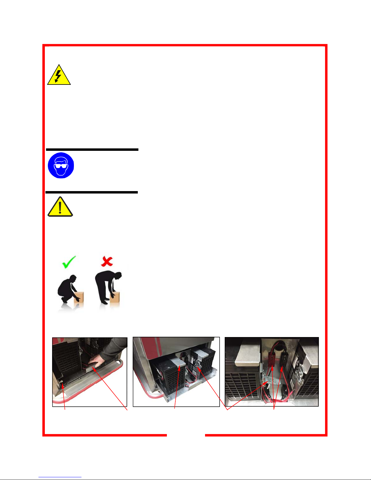
DC POWER SYSTEM... Two on board
batteries to power all electronics, including
heating elements, blower motor, cooling
fans and control board. Full battery charge
will provide 4-6 hours of operation. Robust
power converter and charge controller for
seamless transition from AC wall power
and DC battery power and vice versa. Cart
can be left to charge for as long as the user
wants and will switch to a power saving
mode when fully charged. Cart will operate
while being charged or can be charged
while the unit is cold. Battery life 3-5 years
depending on number of charge cycles.
ELECTRICAL CHARACTERISTICS...
Operates on 120 volts, 60 cycle, single
phase, 1300 watts, 10.8 amps. Ten foot 3
wire rubber cord with 3 prong grounding
plug. NEMA 5-20P. Bright LED digital
temperature and battery charge. Adjusta-
ble brightness for indoor or outdoor view-
ing.
PERFORMANCE...GTH12: preheat to
160°F (71°C) in approximately 50
minutes; 180°F in 60 minutes (82°C); 200°
F (93°C) in 80 minutes. GTH7: preheat to
160°F (71°C) in 25 minutes; 180°F (82°
C) in 40 minutes; 200°F (93°C) in 50
minutes. Temperature range of 160°F to
200°F (71°C to 93°C). Batteries can be
charged in 4 hours or less and have a 4-6
hour run time.
ACCESSORIES/OPTIONS...
Alternate caster sizes and types
Four wheel brakes
Menu card holder (5”x7” or 8.5”x11”)
6” extended width tray slides
Alternate electrical configuration
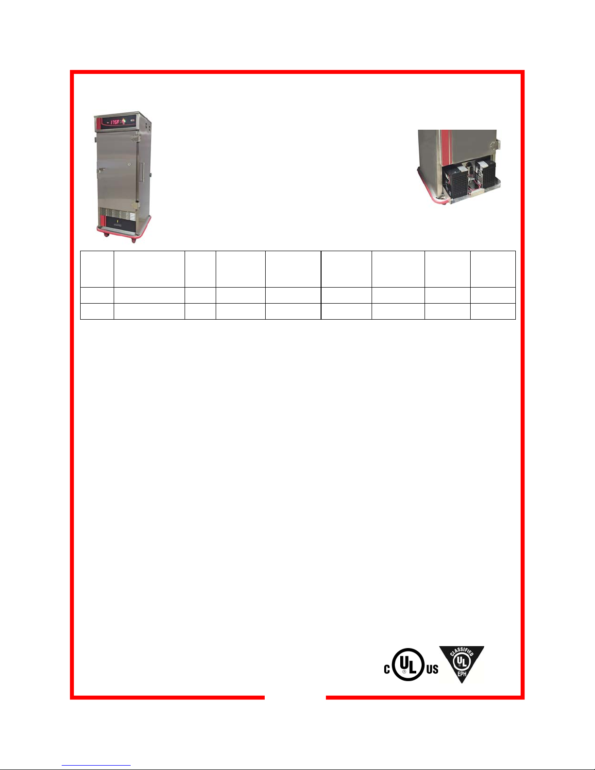
Model Capacity
12”x20” 18”x26” Slide
Pairs Inside Work-
ing Height Height
In (mm)
Depth
In (mm)
Width
In (mm)
Caster
Diameter
In (mm)
Shipping
Weight
Lbs ( kg)
GTH7 14 7 7 26-1/8 (664) 62-3/8 (1584) 37-3/8 (949) 32-5/8 (828) 6 (162) 285 (130)
GTH12 28 14 14 43-5/8 (1108) 79-1/2 (2029) 33-3/8 (949) 32-5/8 (828) 6 (162) 440 (200)
4

5
UNPACKING AND INSTALLATION
WARNING:
Risk of personal injury
Installation procedures must
be performed by a qualified technician
with full knowledge of all applicable
electrical codes. Failure can result in
personal injury and property damage.
CAUTION:
Electrical Shock Hazard
The ground prong of the power cord is
part of a system designed to protect
you from electric shock in the event of
internal damage. DO NOT cut off the
large round ground prong or twist a
blade to fit an existing receptacle.
IMPORTANT:
Power cord is 10' long.
If necessary, contact a li-
censed electrician to install
an appropriate 20 amp electrical cir-
cuit with NEMA 5-20R receptacle. DO
NOT use an extension cord.
IMPORTANT:
Damage to unit due to being
connected to the wrong volt-
age or phase is NOT cov-
ered by warranty. GROUNDING INSTRUCTIONS
This appliance is equipped with a cord having a grounding wire
with a grounding plug which must be plugged into an outlet that is
properly installed and grounded. In the event of an electrical short
circuit, grounding reduces the risk of electric shock by providing an
escape wire for the electrical current.
WARNING-Improper use of the grounding can result in a risk
of electric shock. Consult a qualified electrician or service agent if
the grounding instructions are not completely understood, or if
doubt exists as to whether the appliance is properly grounded.
Unpack the cart and heating unit. Ensure that all packing materials
and protective plastic has been removed from the unit. Inspect all
components for completeness and condition.
NOTE: DO NOT discard the carton or other packing materials until
you have inspected the appliance for hidden damage and tested it
for proper operation. Refer to SHIPPING DAMAGE CLAIM PROCE-
DURE on PAGE 14 of this manual.
Appliance should be thoroughly cleaned before use. See CLEANING
INSTRUCTIONS, page 6.
The cabinet is shipped with the batteries already installed and pre-
charged. Prior to use, batteries will require a 24-hour refreshing
charge to ensure best operation.
Plug the heating unit into a properly grounded NEMA 5-20R electri-
cal receptacle. DO NOT MODIFY CORD PLUG.
Charge batteries for 24 hours.
For first time operation of the cabinet, run on AC (wall) power for 60
minutes. Do not load product into the cabinet. Allow the heat to re-
move any residual oils which may adhere to inside metal surfaces. A
slight emission of smoke is common during the first few hours of
operation.
Before using, familiarize yourself with the
heater controls. Read entire manual before
operating this cart.
ELECTRICAL INFORMATION:
120 volts, 60 Hz, single phase, 1300 watts, 10.8 Amps. Ten foot 3
wire rubber cord with 3 prong grounding plug. NEMA 5-20P.
BATTERY INFORMATION:
DC (battery) Power: Two 12 volt 539 watts/cell batteries. Non-
spillable Absorbed Electrolyte type; Electrical Storage Valve Regu-
lated Lead-Acid (VRLA) Battery with Absorbed Glass Mat (AGM)

6
CLEANING
Turn the main power switch OFF, unplug and allow the unit to cool be-
fore cleaning. DO NOT spray or splash water on the heater, control pan-
el, timer, wiring or in the battery compartment.
1. Racks or shelves are easily removed without tools for cleaning, Simply
lift up and pull out. The tray racks may be hand washed or run through
an automatic washer.
2. To clean stainless steel surfaces use only cleansers, detergents, de-
greasers, or sanitizers that are certified to be "chloride-free" and
"phosphate-free," and cleansers, degreasers, or sanitizers only in the
recommended concentrations. DO NOT exceed recommended con-
centrations or mixing ratios. After cleaning and sanitizing, rinse all
exposed surfaces thoroughly with large amounts of clean, clear water.
Wipe off any standing liquid or residue from all surfaces, corners and
rear edges.
3. Vinyl trim should be washed with a chlorine-free detergent and water.
Rinse thoroughly with clear water and allow to dry. Never use abra-
sive cleaners, waxes, car polish, or substances containing strong aro-
matic solvents or alcohol. Use of direct steam / hot water cleaning
at temperatures above 190°F may result in “bubbling” or loosening of
vinyl adhesive.
4. After all parts are dry, reinstall them and then replace the heating unit.
WARNING: ELECTRIC
SHOCK HAZARD
Unplug the unit from
electric power before
performing cleaning or maintenance.
WARNING:
BURN HAZARD
Allow the unit to cool
before performing any
cleaning or maintenance procedures.
WARNING: ELECTRIC
SHOCK HAZARD
DO NOT spray or splash
water on the heater, con-
trol panel, timer or wiring.
IMPORTANT: Cleansers, detergents, degreasers, sanitizers or bleaching agents that contain chlorides or
phosphates will cause permanent damage to stainless steel products. This damage appears as pits,
eruptions, voids, small holes, cracks, severe discolorations or dulling of the metal finish. Water with a high
chlorine content can also damage stainless steel. If unsure of your water quality, we recommend you have it
tested. THIS DAMAGE IS PERMANENT, COSTLY TO REPAIR, AND IS NOT COVERED BY WARRANTY.
PURPOSE FREQUENCY CLEANING AGENT METHOD OF APPLICATION
Routine
cleaning Daily Soap, ammonia,
detergent and water Swab with cloth.
Rinse with clear water, wipe dry.
Smears
and
fingerprints
As needed Stainless steel cleaner,
similar products Rub with cloth as directed on package.
Rub in direction of grain of stainless steel.
Do not use on vinyl trim or control panel.
Stubborn spots
and
stains
Daily or as needed Any chloride-free or
phosphate-free
cleanser
Apply with damp sponge or cloth.
Rub in direction of grain. Rinse thoroughly.
Do not use on vinyl trim or control panel.
Hard
water spots Daily or as needed Vinegar Swab with cloth.
Rinse with clear water, wipe dry.
RECOMMENDED "TIPS" FOR CLEANING STAINLESS STEEL
CAUTION: CART
DAMAGE
Do not tip cart onto the
doors to drain excess
water. Permanent damage to the
doors and hinges will result. Use a
clean dry cloth to mop any excess
water inside cabinet after cleaning.

IMPORTANT:
Cabinet AC power re-
quires a 15 amp electri-
cal circuit with NEMA 5-
20R receptacle. DO NOT use a
receptacle that is not rated and
grounded for 20 amp service and
do not use an extension cord. Veri-
fy electrical specifications on the
serial tag located on the cabinet.
DAILY OPERATION
CAUTION: SAFE
FOOD HOLDING
PRACTICES
RECOMMENDED
Cooking food to a safe tempera-
ture, holding at a temperature of at
least 140°F is critical in the preven-
tion of foodborne illness. Hold only
cooked, hot food at 140°F or high-
er. This cabinet is not intended to
cook or reheat food. Food must be
at appropriate temperature before
being placed into cabinet.
7
Battery charge level
(displays % or hours
remaining)
Power Button
Up and Down Arrow
buttons to set temperature Battery Button: press to
display % or time remaining
on battery charge
Set/Actual Temperature
Button; press to view actual
temperature
Temperature display
TO DIM THE DISPLAY Press and hold the Battery
Button and push the DOWN ARROW until desired
level of brightness is displayed.
TO BRIGHTEN THE DISPLAY Press and hold the
Battery Button and press the UP ARROW until the
desired level of brightness is displayed.
1) With the unit turned “Off”, plug the power cord into an AC
socket.
2) Press the Power Button located on the front of the control
board to turn the unit “On”.
3) Using Up and Down Arrows, set cabinet desired temperature.
NOTE: Display will show cabinet temperature setting. Press
the Temperature Button to view the actual cabinet tempera-
ture.
4) The display will show “PrE” until the unit has reached the de-
sired set point. Pre-heat to desired temperature (see preheat
times and temperatures for each model in box to the left).
When preheat is complete, it will display the set temperature.
5) The actual temperature of the food compartment can be seen
by pressing the Set/Actual Button once.
6) Load product into the cabinet, starting from the bottom up.
7) To disconnect from AC wall power and go to DC battery pow-
er for transport, turn off cabinet, unplug from AC and then turn
the cabinet back on. It will now run on battery power. Run
time will be about 4 hours on a full battery charge.
8) When removing product from the cart, start at the bottom and
work to the top position. This keeps food hotter and elimi-
nates spillage onto lower items.
9) Once the battery requires charging or the user wants to begin
charging the battery again, the unit should first be turned “Off”
then plugged into the wall socket. The unit can then be left
“Off” to charge more quickly or it can be turned “On” again to
maintain active temperature and charge the battery which will
take more time.
10) It is recommended that the unit be fully charged before un-
plugging and running on battery to maximize the life of the
battery over time.
PREHEAT TIMES &
TEMPERATURES
GTH7: preheat to 160°F (71° C) in
25 minutes; 180°F (82°C) in 40
minutes; 200°F (93°C) in 50
minutes.
GTH12: preheat to 160°F (71° C)
in approximately 50 minutes; 180°
F in 60 minutes (82°C); 200°F (93°
C) in 80 minutes.

8
GENERAL MAINTENANCE INSTRUCTIONS
CASTERS
Some casters are equipped with Zerk grease fittings so that they may be easily lubricated
with a grease gun. Recommended lubrication is at least once every six months. Lubrica-
tion will be required more frequently if carts are cleaned with a hot water or steam clean-
ing system. Casters with special bearings are recommended for frequent cart wash or
steam cleaning situations.
LATCHES
Check frequently to insure that all door latches are secure. Latches may become “sticky”
due to residue build-up from daily use and cleaning. Lubricate latches regularly with WD-
40, silicone spray, graphite or other commercial lubricants for stainless steel products. Do
not use oil.
PERIMETER BUMPERS
Vinyl which has been dislodged from the channel due to severe bumping or scraping can
be pried back into place with a common screwdriver.
WARNING: The batteries used in this appliance are large and heavy and pose a risk of
personal injury. Use caution when removing/replacing batteries and remove/replace one
at a time. Due to the weight, they can cause the appliance to tip. Use extreme care. Do
not perform removal or replacement alone.
The batteries contain chemicals that may cause a fire or explosion and pose health haz-
ards if there is accidental exposure to them. See page 2 for further instructions regarding
handling of batteries. Use special care when performing any cleaning, maintenance or
battery replacement. Get assistance if necessary and use all protective gear noted on
page 2.

9
BATTERY REPLACEMENT
SAFETY EQUIP-
MENT REQUIRED
Gloves and safety glass-
es must be worn when
handling the batteries.
WARNING: RISK OF
PERSONAL INJURY
Batteries are HEAVY
and weigh 100 lbs
(45kg) each. Use caution when
lifting. Use handles when lifting.
Use proper lifting technique and lift
with a straight back and knees.
Get assistance if needed.
WARNING:
ELECTRICAL SHOCK
HAZARD
Do not alter or change wiring or
Anderson connector configuration.
Do not remove terminal covers,
rings, terminal screws or wires from
battery terminals unless trained.
Remove one battery at a time.
Completely remove the first battery
from the cart and then the second
battery.
CAUTION: MAKE SURE CABINET IS TURNED OFF AND UN-
PLUGGED BEFORE PERFORMING THESE PROCEDURES.
CABINET MUST BE COOL AND ALL FOOD MUST BE RE-
MOVED.
REMOVAL
1) Make sure the casters are in the locked position prior to re-
moving the battery cover.
2) To remove batteries, first, remove the battery cover panel
by lifting up using the inset handle. Pull the handle out and
away from the cart and then down to completely remove the
cover.
3) Next, pull the knobs (Fig 1) on the left and right sides of the
battery tray towards the center of the cart. Twist the knobs
one quarter turn until they remain in the out (“unlocked”)
position.
4) Pull the battery tray away from the cart using the formed
metal handle in the center of the battery tray (Fig. 1 and 2).
5) Unplug both Anderson Connectors (Fig. 3) before removing
the batteries. Do not pull wires. Pull down on the plastic
housing to disconnect the batteries.
6) Choose one battery to remove first. On the battery latch,
flip the turnkey up so that it is horizontal and turn it counter
clockwise until the latch released from the lip (Fig. 3). Let
the latch fold down and away from the battery.
7) Raise the front edge of the battery hold down bracket (Fig.
2) over the front edge of the battery while sliding the battery
out of the bracket.
8) Before the battery reaches the edge of the battery tray, stop
sliding the battery. Continue sliding the battery out while
holding both handles. Gently lower the battery to the
ground or to a transfer dolly. Make sure ground is level and
the dolly is locked in place.
9) Repeat battery removal steps for the second battery.
Knobs (one on left
side and one on
right side)
Figure 1 Figure 2
Figure 3
Pull handle for
battery tray Anderson
connectors
Turnkey battery
latch
Battery hold
down bracket

10
BATTERY REPLACEMENT
SAFETY EQUIP-
MENT REQUIRED
Gloves and safety glass-
es must be worn when
handling the batteries.
CAUTION: HEAVY
Batteries weight 100 lbs
(45kg) each. Use cau-
tion when lifting. Use
handles when lifting. Use proper
lifting technique and lift with a
straight back and knees. Get as-
sistance if needed.
WARNING:
ELECTRICAL SHOCK
HAZARD
Do not alter or change wiring or
Anderson connector configuration.
Do not remove terminal covers,
rings, terminal screws or wires from
battery terminals unless trained.
Remove one battery at a time.
Completely remove the first battery
from the cart and then the second
battery.
CAUTION: MAKE SURE CABINET IS TURNED OFF AND UN-
PLUGGED BEFORE PERFORMING THESE PROCEDURES.
CABINET MUST BE COOL AND ALL FOOD MUST BE RE-
MOVED.
INSTALLATION
1) Make sure the casters are in the locked position prior to in-
stalling batteries.
2) To install batteries, first, remove the battery cover panel by
lifting up using the inset handle. Pull the handle out and
away from the cart and then down to completely remove the
cover.
3) Next, pull the knobs on the left and right sides of the battery
tray towards the center of the cart. Twist the knobs one quar-
ter turn until they remain in the out (“unlocked”) position (Fig.
1).
4) Pull the battery tray away from the cart using the formed met-
al handle in the center of the battery tray (Fig.1).
5) Choose one battery to install first. Use the handles on the
battery to lift the battery onto the battery tray.
6) Slide the battery back into the cart while lifting up on the bat-
tery bracket until the battery hits the back of the bracket.
7) Lower the front edge of the battery bracket over the front
edge of the battery (Fig. 2).
8) On the battery latch, fold the latch up and towards the battery
until it comes to a vertical position and the latch is centered
over the lip (Fig. 2 and 3). Flip the turnkey up so that it is
horizontal and turn it clockwise until the latch engaged to the
lip and fold the turnkey into the flat, locked position.
9) Repeat these steps with the second battery.
10) Plug in both Anderson Connectors (Fig. 3).
11) Push the battery tray into the cart using the formed metal
handle in the center of the battery tray until it is as far back in
the cart as it can go.
Knobs (one on left
side and one on
right side)
Figure 1 Figure 2
Figure 3
Pull handle for
battery tray Anderson
connectors
Turnkey battery
latch
Battery hold
down bracket
Continued on next page

11
BATTERY REPLACEMENT
SAFETY EQUIP-
MENT REQUIRED
Gloves and safety glass-
es must be worn when
handling the batteries.
CAUTION: HEAVY
Batteries weight 100 lbs
(45kg) each. Use cau-
tion when lifting. Use
handles when lifting. Use proper
lifting technique and lift with a
straight back and knees. Get as-
sistance if needed.
WARNING:
ELECTRICAL SHOCK
HAZARD
Do not alter or change wiring or
Anderson connector configuration.
Do not remove terminal covers,
rings, terminal screws or wires from
battery terminals unless trained.
Remove one battery at a time.
Completely remove the first battery
from the cart and then the second
battery.
CAUTION: MAKE SURE CABINET IS TURNED OFF AND UN-
PLUGGED BEFORE PERFORMING THESE PROCEDURES.
CABINET MUST BE COOL AND ALL FOOD MUST BE RE-
MOVED.
INSTALLATION (CONTINUED)
12) Next, twist the knobs one quarter turn until they release from
the out (“unlocked”) position (Fig. 1). Push the knobs on the
left and right sides of the battery tray towards the outside of
the cart until they are seated in their locating holes.
13) Install the battery cover panel by inserting the top edge of the
battery cover up and behind the front vail. Swing the bottom
edge of the cover panel down and towards the cart until the
tabs of the panel are lined up with the slots on the cart.
14) Let the panel fall down into its secured position.
15) Make sure to unlock the casters in order to move the cabinet.
Knobs (one on left
side and one on
right side)
Figure 1 Figure 2
Figure 3
Pull handle for
battery tray Anderson
connectors
Turnkey battery
latch
Battery hold
down bracket

12
WIRING DIAGRAM & PARTS LIST
Part Number Description
18100-0159 Locking Spring Plunger
18301-5284 6” Red Rigid Caster
18301-5293 6” Red Swivel Caster with Brake
18301-8321 Threaded Stem Ball Caster
18302-0110 Link Lock Spring
18303-0082 Snap-in Pocket Pull
18312-0671 Battery Compartment Overlay
18312-0673 Control Overlay
18600-0142 275F Hi-Limit-Auto QC Gold
18602-0309 Fuse 16 Amp, 400VDC, 5x20mm
18602-0312 Fuse Holder, 16A, 32VDC
18602-0317 Class - Fuse, 50A
18602-0318 Fuse Holder, Class-T 300V
18602-0319 Relay-24VDC Coil, 30A cont.
18603-0004 Wiring Kit
18603-0006 3’ Patch Cord
18603-0007 AC Detection Cord
18603-5018 Fan Blade
1300W, 120V,
10.8A, 60Hz, single
phase, NEMA 5-20P
Part Number Description
18605-0017 14/3 HSJO Cord w/ 5-20 Plug
18607-0019 Terminal Block 6 pos. #603
18612-0162 Hoop Element #1 400W
18612-0163 Hoop Element #2 400W
18614-0272 Fan Guard, #SC120-W15
18614-0275 Fan Guard, #SC80-W2
18614-0303 Muffin Fan, 24VDC, 26 CFM
18614-0392 Blower Motor, 24VDC, 1500 RPM
18614-0393 4.72”x1.57” 24VDC 105 CFM
18616-0399 Xantrex C40 CHRG Controller
18616-0401 12V, 540WPC 155AH Battery
18616-0402 Gridless Hot Display Board
18616-0404 Gridless Hot Power Board
18616-0405 Thermistor, 50K, 4” Probe
18616-0406 Blocking Diode, 600V, 70A
18616-0408 Power Converter, 1200W, 30VDC
18616-9998 Cord Grip
29034-0282 Silicone Sponge
NOTE:
The technical content of this manual, including any wir-
ing diagrams, schematics, parts breakdown illustrations
and / or adjustment procedures, is intended for use
ONLY by qualified technical personnel.
NOTE:
For warranty service, call Carter-Hoffmann direct at 800-
323-9793 for authorization, we will dispatch the nearest
authorized service agency.

WIRING SCHEMATIC
13

14
TROUBLESHOOTING SUGGESTIONS
PROBLEM PROBABLE CAUSE POSSIBLE REMEDY
No power to unit,
No light on display
Motor not running
Not plugged in or circuit breaker off or
tripped Plug into receptacle. Reset circuit
breaker, check facility circuit breaker
Main switch damaged Check main power switch, replace if
damaged
Anderson battery plug to disconnected Reconnect Anderson plug
Damaged power cord Replace cord
Bad fuse. Note: this indicates further
malfunction with another component. Do
not attempt to replace fuse.
Call service technician
Dead battery Replace both batteries
Hi-limit safety tripped Allow unit to cool, hi-limit will reset auto-
matically, or replace
Unit does not hold temperature Damaged door gasket Replace gasket
Damaged door latch Replace defective latch
Temp probe damaged Replace probe
Door gap, out of alignment Adjust door hinging and strike
Unit does not heat Cabinet temp above setpoint
(setpoint too low) Turn thermostat setpoint up
Check thermometer calibration
Dead battery Replace both batteries
Damaged wiring Repair wiring
Damaged relay Replace relay
Damaged controller Replace controller
Damaged heating element Perform ohm reading, Replace element
Unit overheats Setpoint too high Change setpoint
Thermostat damaged Replace thermostat
Defective hi-limit control Replace hi-limit
Blower fan jammed Find source of fan binding
Blower motor not running Damaged fan motor Replace motor
Fuse blown Call service technician
Blower fan jammed Find source of fan binding
Relay is “chattering” Check proper wiring to switch Repair wiring or replace switch
Red malfunction light is illuminated Appliance malfunction Call service technician
Display reads “E002” or “CHrg BAtt” Dead batteries Recharge batteries
Damaged power supply Replace power supply
Damaged charge controller Replace charge controller and make
sure both cooling fans are working
properly
Door is open too much or not sealed Replace door gasket or realign door
Damaged batteries Replace both batteries
Damaged diode Replace diode and make sure both
cooling fans are working properly
50A fuse blown Replace blown fuse and check ALL
wiring and components for shorts
Not charging or battery life is diminished

SERVICE EXPECTATIONS
SERVICE PHILOSOPHY
For almost sixty years, Carter-Hoffmann has enjoyed a reputation for manufacturing rugged, dependable
foodservice equipment that permits foodservice professionals serve more food products to more
people, and thus, to grow their business.
Our goal is not only to provide the best food service equipment for the price, but also to back it up with after-sale
service that is responsive fast, efficient and professional. To ensure a clear understanding of our goals, expecta-
tions, and responsibilities, we have prepared this brief document.
Carter-Hoffmann products are innovative and efficient. They are easy to use, easy to clean and easy
to maintain. Although the products are quite reliable they are also designed for easy repair. We believe that a
malfunction to a Carter-Hoffmann product should cause as little inconvenience to the customer as possible. Our
aim is to provide “same day”/first time fix” repair service on all of our products. We are dedicated to making eve-
ry aspect of our customer service the standard by which others are judged.
END-USER RESPONSIBILITIES
While we all strive to serve our mutual customers as well as possible that does not mean that
the end-user (including his employees) does not share some responsibilities.
1. All shipping damage must be noted on the freight bill when the shipment is received. Any freight
damages must be collected from the Freight Company, NOT Carter-Hoffmann.
2. The end-user should be advised beforehand to carefully unpack and inspect all products when they are
received BEFORE SIGNING THE SHIPPER'S RECEIPT OF DELIVERY.
3. The end-user must provide a safe, dry, level surface for the equipment to be placed upon.
4. The end-user must provide the proper electrical supply. All in-wall electrical modifications are to
be completed by a licensed electrician. All building modifications are the responsibility of the end-user.
5. The end-user must operate, clean and maintain the equipment in accordance with the
procedures described in the Operation Manual.
6. Carter-Hoffmann is NOT responsible for any loss of the customer’s income, loss of food product, extra labor
charges, or any other incidental or consequential costs as a result of the malfunction of our product.
7. The end-user shall allow for on-premises repair of the equipment to be completed at a mutually
convenient place and time.
WARRANTY SERVICE
1. Warranty service is to be initiated by authorized Carter-Hoffmann personnel only.
2. The service provider is NOT authorized to change or extend any of the terms or conditions of our warranty.
3. Initial freight damage is NOT covered by the product warranty.
CONFIDENTIALITY
1. The end user and all his employees and sub-agents shall protect and keep confidential Carter-Hoffmann’s
proprietary designs, information, and knowledge.
2. All literature and informational materials provided by Carter-Hoffmann are to be considered confidential; they
remain Carter-Hoffmann’s property; and are not to be reproduced without our prior written consent.
SHIPPING DAMAGE CLAIM PROCEDURE
NOTE: For your protection, please note that equipment in this shipment was carefully inspected and packaged
by skilled personnel before leaving the factory. Upon acceptance of this shipment, the transportation company
assumes full responsibility for its safe delivery.
IF SHIPMENT ARRIVES DAMAGED:
1. VISIBLE LOSS OR DAMAGE: Be certain that any visible loss or damage is noted on the freight bill or ex-
press receipt, and that the note of loss or damage is signed by the delivery person.
2. FILE CLAIM FOR DAMAGE IMMEDIATELY: Regardless of the extent of the damage.
3. CONCEALED LOSS OR DAMAGE: if damage is unnoticed until the merchandise is unpacked, notify the
transportation company or carrier immediately, and file “CONCEALED DAMAGE” claim with them. This
should be done within ten (10) days from the date the delivery was made to you. Be sure to retain the
container for inspection.
4. Carter-Hoffmann cannot assume liability for damage or loss incurred in transit. We will, however, at your
request, supply you with the necessary documents to support your claim.
15

16
CARTER-HOFFMANN WARRANTY
Carter-Hoffmann warrants to the initial purchaser
of its standard Carter Line Products that Carter-Hoffmann will, at its
option, repair or replace, during the warranty period set forth below, any part of such products made necessary
due to a
defect in material or workmanship which is present
when the product leaves its factory and which
manifests
itself during the warranty period under
normal use and service.
This warranty applies only to original equipment owned and possessed by the initial purchaser and the warranty
period begins on the date of original shipment from the Carter-Hoffmann factory and extends as follows: to com-
ponent parts and labor for one year; to refrigeration compressor unit for one year (limited to replacement of the
unit only-not to include the labor for removal, repair or replacement)
. Repair or replacement under this warranty will
be performed, unless otherwise authorized in writing by Carter-Hoffmann, at its factory. All parts or components to be re-
paired or replaced under this warranty are to be shipped prepaid to Carter-Hoffmann, with reimbursement credit for such part
or component to be given if found by Carter-Hoffmann to be defective.
Carter-Hoffmann neither makes nor assumes and does not authorize any other person to make or assume any
obligation or liability in connection with its products other than that covered in this warranty. This warranty ap-
plies only within the continental United States and Canada. In Alaska and Hawaii, this warranty applies only to
and is limited to the supply of replacement parts.
WARRANTY EXCLUSIONS AND LIMITATIONS
ANY IMPLIED WARRANTY OF MERCHANTABILITY OR FITNESS FOR A PARTICULAR PURPOSE IS HERE-
BY SPECIFICALLY DISCLAIMED BY CARTER-HOFFMANN. There are no warranties, express or implied,
which extend beyond the description on the face thereof.
This warranty does not cover and Carter-Hoffmann shall not under any circumstances be liable for any inci-
dental, consequential or other damages (such as injury to persons or property, loss of time, inconvenience, loss
of use, loss of business or profits, or other matters not specifically covered) arising in connection with the use of,
inability to use, or failure of these products.
Note: Due to our continuous process of product improvement and innovation, all listed specifications subject to
change.
Carter-Hoffmann
1551 McCormick Ave.
Mundelein, Illinois, 60060 USA
Phone: 847-362-5500 Toll free: 800-323-9793 Fax: 847-367-8981
Sales and Marketing E-mail: sales@carter-hoffmann.com
Company Website: www.carter-hoffmann.com
This manual suits for next models
1
Table of contents
Popular Heater manuals by other brands

Kermi
Kermi Credo-Duo II Assembly and operating instructions

Toyostove
Toyostove WC-105 Operating and maintenance instructions

Webasto
Webasto DBW 2020 Service and repair manual

Quadro
Quadro HOL-1320T user manual

Dimplex
Dimplex PLX050ENC Installation and operating instructions

EINHELL
EINHELL KH 1500/1 Original operating instructions