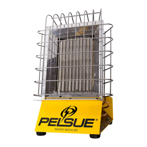
Pelsue 1690D User manual

Part #120944-001
Product Manual:
Model #1690D
In-Line Heater
T.A. Pelsue Company
2500 South Tejon Street
Englewood, Colorado, USA 80110
Tel. 800-525-8460 or 303-936-7432
Fax. 303-934-5581
Internet: www.pelsue.com
Email: [email protected]
ISO 9001 Certified

#120944-001 - Product Manual: Model #1690D In-Line Heater - Revision 12 - Date: 07-02-2015
Page 2

#120944-001 - Product Manual: Model #1690D In-Line Heater - Revision 12 - Date: 07-02-2015 Page 3
Since our inception in 1963 – the T.A. Pelsue
Company has designed and manufactured high
quality equipment to improve the personnel ef-
ciency and working conditions in various under-
ground, conned, and outdoor areas.
Founded by T. Allen Pelsue, the company has estab-
lished a continuing reputation for excellence in the
production of ne products for a broad spectrum of
industry throughout the world.
Now, in our second generation of family direction,
continued commitment to innovation and quality
makes Pelsue a leading source of equipment for
many types of conned spaces. We specialize
in safety, retrieval, fall arrest, ventilation, cable
placing, splicing, and maintenance nationally and
abroad. With more than 70,000 square feet of facil-
ities available, Pelsue continues the dedication that
has made us pre-eminent in this eld.
ISO 9001 Certified

#120944-001 - Product Manual: Model #1690D In-Line Heater - Revision 12 - Date: 07-02-2015
Page 4
Table of Contents
Section Description Page #
1.0......................................General Information.................................. 5
1.1...........................Quality Policy
1.2...........................Pelsue Product Warranty
2.0......................................Introduction & Product Information........ 7
2.1...........................Serial Number
3.1...........................Parts Diagram & List
3.2...........................Wiring Diagram
4.1...........................Safety Alert Symbol
4.2...........................General Safety Information
5.0......................................Product Operation.....................................14
5.1...........................Product Description & Capabilities
5.2...........................Start-Up & Operating Procedures

#120944-001 - Product Manual: Model #1690D In-Line Heater - Revision 12 - Date: 07-02-2015 Page 5
1.0 General Information
T.A. Pelsue Company
Quality Policy
OUR GOAL IS THE PURSUIT OF NEVER-ENDING IMPROVEMENT IN
PRODUCT QUALITY AND BUSINESS SYSTEMS.
METHODS TO BE EMPLOYED IN ATTAINING THIS GOAL WILL INCLUDE
NEW PRODUCT QUALITY PLANNING, EMPLOYEE TRAINING, AND
UTILIZATION OF EMPLOYEE INVOLVEMENT GROUPS TO SOLVE
PROBLEMS.
IN AN INCREASINGLY COMPETITIVE MARKETPLACE, ENSURING
CUSTOMER SATISFACTION IS ONE OF THE DIFFERENTIATORS THAT
SETS YOU APART FROM THE PACK AND YIELDS A COMPETITIVE
ADVANTAGE.
THEREFORE, WE WILL SUPPORT TOTAL CUSTOMER SATISFACTION
BY
IMPLEMENTING THE AND PROVIDING
THE NECESSARY ATMOSPHERE AND TRAINING TO NURTURE THIS
CONCEPT THROUGHOUT OUR ORGANIZATION.
WE WILL MAKE EVERY BUSINESS DECISION AS THOUGH THE
QUALITY OF
THE PART OR SERVICE PROVIDED WAS DESTINED FOR OUR OWN
OR OUR FAMILY’S USE. WE WILL ALWAYS THINK
EVERY T.A. PELSUE COMPANY EMPLOYEE IS EXPECTED TO COMMIT TO
THIS PHILOSOPHY IN THE PERFORMANCE OF HIS OR HER DAILY TASKS.
QUALITY FIRST!
T.A. PELSUE COMPANY SENIOR MANAGEMENT TEAM
1.1 Quality Policy

#120944-001 - Product Manual: Model #1690D In-Line Heater - Revision 12 - Date: 07-02-2015
Page 6
1.2 - Pelsue Product Warranty
PELSUE PORTABLE PRODUCT WARRANTY
Pelsue products are designed and engineered to perform as stated in published specifications. Quality materials
and workmanship are used in the manufacture of this product. With regular maintenance and proper care,
Pelsue equipment provides many trouble free hours of operation.
The T.A. Pelsue Company warrants to the buyer that material furnished will conform to specifications and will be
free from defects in material and workmanship from the date of shipment to the original buyer, for the period
listed by product description on the reverse side of this warranty statement.
In the event of failure of any components of a Pelsue product within the warranty period, service must be pre-
approved by the T.A. Pelsue Company and service must be performed by the T.A. Pelsue Company Parts and
Service Department in Englewood Colorado, or at the option of T.A. Pelsue Company, service may be
performed at any designated service center, which may include any authorized service center for the component
manufacture.
Damage or failure due to misuse, mishandling, or unauthorized modifications will not be covered by this
warranty. Unless otherwise agreed, the T.A. Pelsue Company shall repair or replace the defective components
within (30) calendar days of notice of failure. T.A. Pelsue Company’s obligation hereunder, shall be limited to the
repair or replacement of the product or component as set forth above, and shall not include any liability
whatsoever for damages caused by such failure, including but not limited to consequential or incidental
damages flowing from use or lack of use of product.
Any replacement, repair, modification, installation or other service performed by the T.A. Pelsue Company shall
be warranted by the remainder of the unexpired period of the warranty, or for a period of (90) calendar days,
whichever is longer.
All materials or parts returned for credit or warranty shall be returned only with prior approval, and will be subject
to factory inspection before credit is allowed. Parts claimed defective will be replaced upon request and will be
invoiced as purchased, subject to credit when the parts claimed to be defective have been received and
examined by the factory.
This warranty is expressly in lieu of all other warranties expressed or implied, including any warranties of
merchantability or warranties of fitness for any particular use and all other obligations or liabilities in connection
with the sale of this equipment.
Product Description Warranty Coverage*
x
Ventilators...................................................................................... 1 year
x
Heaters .......................................................................................... 1 year
x
Ventilator Hoses/Ducts .................................................................. 3 months
x
Pel-Cans and Caddys .................................................................... 1 year
x
Hose Adapters ............................................................................... 1 year
x
Manhole Shields & Manhole Guards.............................................. 1 year
x
Pel-Brite Work Lights ..................................................................... 6 months
x
Planks and Plank Supports ............................................................ 6 months
x
Duct Rodders and Accessories...................................................... 6 months
x
Submersible Pumps....................................................................... 6 months
x
Discharge and Suction Hoses for Pumps....................................... 3 months
x
Wheel Chocks................................................................................ 1 year
*From date of shipment to original buyer.
T.A. Pelsue Company, 2500 South Tejon Street, Englewood, Colorado 80110, 800-525-8460

#120944-001 - Product Manual: Model #1690D In-Line Heater - Revision 12 - Date: 07-02-2015 Page 7
2.0 - Introduction & Product Information
MODEL:__________________________________________
Serial Number :_____________________________________
Congratulations on your choice of a Pelsue Model #1690D In-Line Heater to compliment your conned space heating
and ventilation operation. This equipment has been designed and manufactured to exceed conned space requirements
and regulations in order to meet the needs of the discriminating operator for the efcient and safe operations of person-
nel in a conned space.
Safe, efcient and trouble-free operation and maintenance of the system requires that anyone who will be operating,
maintaining, or inspecting the equipment, read, understand and follow all the operation, safety, maintenance, and inspec-
tion instructions contained within this manual. This manual covers the Pelsue Model #1690D In-Line Heater. Use the
Table of Contents as a guide to nd specic information.
Keep this manual handy for frequent reference and to pass on to new operators.
This product is a part of a system for conned space
ventilation operations. The user must read, understand
and follow the instructions contained in this manual
before using this equipment. Failure to follow these
instructions could result in serious injury or death.
2.1 - Serial Number
Always give your dealer the serial number of your Pelsue In-Line Heater
product when ordering parts or requesting service or other information.
The specication & rating decal is permanently embossed with a serial
number. The rating decal is located on the front of the control box housing
cover, as shown in
Fig. 2a
. The specication & rating decal will appear as
shown to the right in
Fig. 2b.
A space has been provided below for the
recording of the serial number for future reference.
Figure 2b: #1690D
Serial Number Plate
Figure 2a: Serial Number
Location
#1690D
Serial
Number
Location
67$5783
&RQQHFW'WRUHJXODWHGSURSDQHVXSSO\
3OXJ'LQWRSRZHUVRXUFH9$&
+]
3ODFHWKH'%ORZHULQOLQHDQGSOXJLQWR
WKH9$&UHFHSWDFOHORFDWHGRQWKHKHDWHU
,QVWDOODQGLDPHWHU[ORQJGXFWRQWRWKH
RXWOHWRIWKHKHDWHU
7XUQWKHKHDWHUVZLWFKWR21
&(57,),('$,5'(/,9(5<
0,1&/($5$1&(72&20%867,%/(6)8(/
25,),&(6,=()25,167$//$7,21
$763(&,),('$/7,78'(
0$1,)2/'
35(6685(
0,1,080,1/(7725(*8/$7253529,'('
)25385326(62),1387$'-8670(17
0$;,080,1/(772
5(*8/$7253529,'('
&)0
FXPPLQ
)5(($,5 ;
%(1'
723
6,'(6
+($7(5287/(7
+26((1'
;
%(1'6
&)0
FXPPLQ
&)0
FXPPLQ
*$635(6685()2586(:,7+3523$1(*$621/<
;
:&
36,
36,
23(5$7,21,16758&7,216
02'(/'
,1/,1(+($7(5
9$&+=$03
6(5,$/1R
'
6RXWK7HMRQ6WUHHW
(QJOHZRRG&RORUDGR
5
&
86
:$51,1*
,1387%78K
$16,=D86$
&6$D&$1$'$
7KLVHTXLSPHQWLVIRURXWGRRUXVHRQO\DQGIRURSHUDWLRQLQDPELHQWWHPSHUDWXUHVGRZQWR
)
&7RDYRLGVHULRXV
LQMXU\GHDWKDQGSURSHUW\GDPDJHUHDGWKHVDIHW\ZDUQLQJVDQGLQVWUXFWLRQVLQFOXGHGLQWKHSURGXFWPDQXDOLQFOXGHGZLWKWKLV
KHDWHU7KLVKHDWHULVGHVLJQHGIRUXVHLQLQGXVWULDOXWLOLW\DSSOLFDWLRQVRQO\,QVWDOODWLRQPXVWEHLQDFFRUGDQFHZLWKORFDO
FRGHVIRUSURSDQHHTXLSPHQW7KLVHTXLSPHQWLVQRWIRUUHVLGHQWLDOXVHRUIRUXVHZLWKPRELOHKRPHV59VFDPSHUVHWF
0DLQWDLQDOOVSHFLILHGFOHDUDQFHVIURPFRPEXVWLEOHVSURSDQHERWWOHVJDVROLQHFRQWDLQHUVDQGVLPLODUIODPPDEOHPDWHULDOV
,QVWDOOWKLVHTXLSPHQWSHUWKHSURGXFWPDQXDOVXSSOLHGZLWKWKHKHDWHU3URSDQHKDVDVWURQJRGRULI\RXVPHOOSURSDQHJDV
'2127VWULNHDPDWFKRUOLJKWHU7XUQRIIDOOFRQWUROVDOORZDWOHDVWPLQXWHVIRUYDSRUVWRGLVSHUVHWKHQFKHFNWKH
HTXLSPHQWIRUOHDNVDQGSURSHURSHUDWLRQSHUWKHRSHUDWLQJLQVWUXFWLRQVORFDWHGZLWKLQWKHSURGXFWPDQXDO,IDOHDNFDQQRWEH
IRXQGDQGRGRULVVWLOOSUHVHQWKDYHWKHHTXLSPHQWFKHFNHGE\DTXDOLILHGVHUYLFHWHFKQLFLDQ
31
6+87'2:1
7XUQRIIWKHSURSDQHF\OLQGHUYDOYHDOORZIXHOWR
EXUQRII
7XUQWKHKHDWHUVZLWFKWR2))
$OORZWKH'%ORZHUWRRSHUDWHIRUPLQXWHV
LQRUGHUWRFRROGRZQWKHKHDWH[FKDQJHU
8QSOXJWKH'%ORZHUIRUPWKH'DQG
UHPRYHWKH'IURPWKHSRZHUDQGIXHO
VRXUFHV

#120944-001 - Product Manual: Model #1690D In-Line Heater - Revision 12 - Date: 07-02-2015
Page 8
3.0 - Conguration & Assembly
Upon initial receipt of the #1690D In-Line Heater, inspect the packaging for any evidence that the product may have
been damaged in shipment. While unpacking the product, inspect all of the components for damage. If damage to any
of the components is discovered, alert the shipping carrier immediately of the damage to the shipment.
Refer to the following parts breakdown diagram (Figure #3.1a) and the accompanying parts list (Table #3.1a) for iden-
tication of parts in the event replacements become necessary. The parts list table displays applicable part numbers,
descriptions, and quantity per assembly.
**Refer to parts list below if replacement parts are required. Replacement parts can be ordered from the T.A. Pelsue
Company at 800-525-8460.
3.1 Parts Diagram & List
Figure 3.1a: #1690D
Parts Diagram
8
31
18
26
39
40
9
27
29
28
30
32
63
62
61
25
60
45
4
21
53
6
49
5
43
67
55
68
66
46
3
52
56
50
51
11
20
19
65
24
48
14
72
71
75
41
42
10
16
12
17
23
44
46
58
54
13
78
43
44
43
43
80
79
57
59
46
76
77

#120944-001 - Product Manual: Model #1690D In-Line Heater - Revision 12 - Date: 07-02-2015 Page 9
Table 3.1a: #1690D
Parts List
3.1 Parts Diagram & List (continued)
'225&21752/%2;$&&(66
(
5(&(37$&/(32/(:,5($039)/86+675$,*+7%/$'(
675$,15(/+8%',$0(7(5
( &25'6(7:02/'('3/8*6-72:5$7('
( 3/8*61$3,1%/$1.%87721',$0(7(5
0$,1+286,1*+286,1*$66(0%/<6,/.6&5((1(':3(/68(/2*2
3$1(/+($76+,(/'68%$66(0%/<
),77,1*1,33/(0137;/21*%5$66
0$,1%$6(3/$7(+286,1*$66(0%/<
/($'+,*+7(16,2163$5.,*1,7,21
+($7(;&+$1*(5:(/'0(17:,7+$,5&2//(&725
6&5((1$,5&2//(&725
6,*+7*/$66137&/($5/(16+(;+($'(/(&7523/$7('
*$6.(763$5.,*1,7(5)/$0(6(1625
63$5.,*1,7(5,*1,7(5)/$0(6(1625(/(&752'(
3$1(/+($76+,(/'723
3,72778%(:(/'0(17:02817,1*%5$&.(7
78%,1*5'%/$&.58%%(5120,1$/',$0(7(5
5,1*,11(5,17$.($602',),('
,
+26($66</3*;/(1*7+/+)(0$/((1'61276+2:1
% 5(*8/$72568%$66(0%/<$6,167$//('
( &/$0378%,1*,'9,1</&2$7('$/80,180675$3
5,9(767$9(;%/,1')/$1*('20(%/$&.',$0(7(5
7233$1(/+286,1*$66(0%/<
:$6+(5)/$77<3($:3/$7('
+$1'/(%/2:(5&/27+5(,1)25&('1(235(1(;
:$6+(5)(1'(57<3($:3/$7('
+,1*(&21752/3$1(/&29(5
&+,01(<:(/'0(17)25,1/,1(+($7(5
&29(5&21752/3$1(/
'(&$/:,5,1*',$*5$0/$''(5',$*5$0127(6/(*(1'1276+2:1
'(&$/(/(&75,&$/*5281',1*,16758&7,2161276+2:1
'(&$/:$51,1**(1(5$/+$=$5'1276+2:1
'(&$/:$51,1*81,786$*(1276+2:1
'(&$/:$51,1*+$=$5'286&21',7,2161276+2:1
'(&$/,'(17,),&$7,215$7,1*6(5,$/%/.6,/9(51276+2:1
6&5(:0$&+,1(75866+($'81&;/*%/$&.
/2&.1871</21,16(5781&%/$&.2;,'(
6&5(:+(;+'81&;3/$7('*5$'(
1 :$6+(5/2&.(;7(51$/7227+
1 6&5(:0$&+,1(3+,/75866+'81&;3/$7('
6&5(:0$&+,1(3+,/75866+';/21*%/$&.
1 :$6+(5/2&.,17(51$/7227+3/$7('
1876(577+,16+((7&5,03,167</(
3$1(/&2172/%2;,17(5,25&20321(17:$//
3$1(/+($76+,(/'&20321(17:$//
5(&7,),(5%5,'*(
( *5200(758%%(5,';2'*5229(',$0(7(5
3/$7($&&(667+(50$//,0,76:,7&+
( *5200(758%%(5,';2'
75$16)250(59$&35,0$5<
&,5&8,7%2$5'/3*,*1,7(59'&75<385*(6(&21'7),
6:,7&+$,535(6685(1250$//<23(1

#120944-001 - Product Manual: Model #1690D In-Line Heater - Revision 12 - Date: 07-02-2015
Page 10
Figure 3.2a: #1690D
Ladder Diagram and Legend
56 120422-001 SWITCH - THERMAL (CUT-OFF), 115 VAC, NORMALLY CLOSED 1
57 68N-023500 SCREW - MACHINE, TRUSS HD, #8-32 UNC X 3/4" PLATED 4
58 68N-004200 WASHER - LOCK, INTERNAL TOOTH, #8, PLATED 13
59 100048-006 NUT - HEX, #6-32 UNC, PLATED 3
60 26E-041310
CABLE ASSEMBLY - CIRCUIT BOARD, CONNECTS TO CONTROL COMPONENTS 1
61 118650-001 CONTROL PANEL - HOUSING ASSEMBLY 1
62 120959-001 SWITCH - ROCKER, SPST, 125/250 VAC 20A, 14VDC 14A 1
63 107336-001 FUSE HOLDER - PANEL MTD. W/ 90° MALE SPADE TERMINAL 1
64 121160-001
DECAL - VENTILATION BLOWER…MUST BE ATTACHED (NOT SHOWN) 1
65 118654-001 MAIN BASE PLATE 1
66 100188-002 FOOT - RUBBER, 1-1/2" OD W/REC WASHER 4
67 62Q-001000 WASHER - 23/64" THK. X 5/16" ID X 1-1/2" OD 4
68 101427-002 SCREW - CAP,HEX HD,1/4"-20 UNC X 3/4" PLATED 4
69 100050-009 WASHER - FLAT, 1/4" IN, TYPE A, W, PLATED 4
70 100048-114 LOCK NUT - HEX, 1/4"-20, NYLON INSERT 4
71 118671-001 BURNER CASTING - AS MACHINED 1
72 108601-001 FITTING - REDUCER BUSHING, 1/4" MNPT X 1/8" FNPT 1
73 120425-001 BAFFLE - BURNER MANIFOLD 1
74 121107-002
SCREW - #8 X 3/8" LG. SELF TAP'G TYPE-F, CUTTING, HEX WASHER HD 1
75 120420-001
ORIFICE - #56 (.0465 DIA) ROUND BARREL PLUG, 1/8"-27 MNPT X 1 3/16" LG 1
76 106858-002 INNER RING - OUTLET SPINNING, PELSUE YELLOW 1
77 111330-001 GRILLE - OUTLET, PLATED IN BLACK OXIDE 1
78 111844-001 SCREW - MACHINE, PHIL TRUSS HD, #8-32 UNC X 3/8", BLACK 4
79 100050-005 WASHER - FLAT, #8, TYPE A, W, PLATED 4
80 100060-007 LOCKNUT - #8-32 UNC, NYLON INSERT 4
3.1 Parts List (continued)
~
~
+
-
209
(P)
TSH
250°F
210°F
206
207
208
204
205
.68" WC
PSL
(N)
FV
BE
I
120V AC
202
203
201
(P)
103
104
(P)
101
102
1A
F1 S1
1 2
(P)
J1
SECONDARY
12V DC
VOLT
BIM
VALVE
POWER
SENSE
GROUND
HI
12V DC
BR
(N)
120V AC
PRIMARY
T1
(N)
(N)
3.2 Ladder and Wiring Diagram
The ladder diagram, below in Figure 3.2a, demonstrates the stepped-down voltage of the control panel and ignition
system, and the relationships between each of the safety switches.
Table 3.1a: #1690D
Parts List (continued)
REMOTE THERMOSTAT RECEPTACLE
THERMOSTAT SELECTOR SWITCH
RECEPTACLE
FUEL SOLENOID VALVE
TEMPERATURE SWITCH - HIGH
CONTROL TRANSFORMER
POWER SWITCH
PRESSURE SWITCH - LOWPSL
S2
T1
J2
TSH
J1
S1
I
FV
IGNITOR
BURNER ELEMENT (SENSOR)
LEGEND
BURNER IGNITION MODULEBIM
F1
BE
FUSE

#120944-001 - Product Manual: Model #1690D In-Line Heater - Revision 12 - Date: 07-02-2015 Page 11
3.2 Wiring Diagram
Shown below in Figure 3.2b, is a wiring diagram of the control box, cordset, and ignition system.
12
17
BR
9
COMM.
-
21
12
10
~
+
22
15
23
~
20
19
T1
16
G
BK
W
16
14
3
21
18
N.O.
8
10
11
18
S
9
6
20
19 3
4
14
8
17
11
G
BK
NP
1
4
1
25
3
2
G
W
VALVE
SOLENOID
PRESSURE
SWITCH
PSL
QUICK DISCONNECT
GROUND
STUD
MAIN HOUSING
COMPARTMENT
IGNITOR
HEAT EXCHANGER
BURNER ELEMENT
(SENSOR)
I
BE
GROUND
HEATER
SECONDARY
TRANSFORMER
CONTROL
PRIMARY
POWER CORD
(16/3 CABLE)
120V AC
F1POWER
BURNER
MODULE
IGNITION
FV
FUEL
CONTROL BOX
THERMAL
SWITCH
TSH
BIM
14/16 BUTT
SPLICE
STUD
GROUND
RECEPT
120V
J1
GROUND
SENSE
VALVE
POWER
VOLT
HI
SWITCH
TOP PANEL
BREAKER
S1 1A
Figure 3.2b: #1690D
Wiring Diagram

#120944-001 - Product Manual: Model #1690D In-Line Heater - Revision 12 - Date: 07-02-2015
Page 12
The following section will address the safety precautions which must be adhered to when working with Pelsue Construc-
tion Heating and Ventilation equipment such as the #1690D In-Line Heater. Any user must familiarize themselves with
the information in this section before utilizing the equipment.
SIGNAL WORDS:
Note the use of the signal words , and with the safety messages. The appropriate signal
word for each message has been selected using the following guidelines:
D Indicates an imminently hazardous situation that, if not avoided, will result in death or serious injury. This
signal word is to be limited to the most extreme situations or for hidden or unseen hazards.
Indicates a potentially hazardous situation that, if not avoided, could result in death or serious injury and
includes obvious and hidden hazards. It may also be used to alert against unsafe practices.
Indicates a potentially hazardous situation that, if not avoided, may result in minor or moderate injury. It
may also be used to alert against unsafe practices.
You are responsible for the safe operation of your Pelsue #1690D In-Line Heater. You must ensure that anyone who will
operate or work around the equipment be familiar with conned space ventilation procedures. This manual will take you
step-by-step through the workings and capabilities of the #1690D In-Line Heater and alert you to all good safety and
operating practices while using the system.
Remember, you are the key to safety. Good safety practices not only protect you but also the people around you. Make
these practices a working part of your safety program. Be certain that everyone operating in or around a conned space
is familiar with the procedures recommended and follows safety precautions. Remember, most accidents can be pre-
vented. Do not risk injury or death by ignoring good safety practices.
• The most important safety device on this equipment is a safe operator. It is the operator’s responsibility to read
and understand all safety and operating instructions in the manual and to follow these. Most accidents can be
avoided.
• A person must understand the operation of this equipment and be trained in it’s usage before operating the
equipment. An untrained operator exposes himself and others to possible serious injury or death.
• Do not modify the equipment in any way. Unauthorized modication may impair the function and/or safety and
could affect the life of the equipment.
• Think SAFETY! Work SAFELY!
4.0 - Safety
4.1 - Safety Alert Symbol
SAFETY ALERT SYMBOL
This Safety Alert symbol means
The Safety Alert symbol identies important safety messages on your Pelsue Con-
ned Space Product and in the manual. When you see this symbol, be alert to the
possibility of personal injury or death. Follow the instruction in the safety message.
Why is this symbol important to you?

#120944-001 - Product Manual: Model #1690D In-Line Heater - Revision 12 - Date: 07-02-2015 Page 13
4.2 - General Safety Information
! CAUTION ! - Be sure the heater is disconnected from the power source before doing any
maintenance or repair work on the blower.
! CAUTION ! - Check all power cords for cuts, frayed ends, or brittle insulation. See parts list
for replacement cord part number.
! CAUTION ! - The user must ensure that the heater is located where it cannot fall into water
inadvertently and the extension cords or plug connections do not lay in water.
Safety Precautions:
It is necessary to follow these safety precautions, each time, prior to using the product.
The Safety Precautions are not limited to, but must include the following items;
1. Do not use the heater for anything other than its intended use. The heater is primarily intended for the temporary
heating of manholes, vaults, and buildings under construction or repair.
2. Do not wear loose clothing that can become entangled in operating machinery. Do not operate the heater without
inlet or outlet screen guards in place. Do not place ngers or any other object through inlet or outlet screens.
3. Heater and fuel supply installation must conform with local codes, or in absence thereof, with ANSI/NFPA 58-1986 (or
CAN/CGA B149.2 in Canada). The heater can be connected to any liquid propane (vapor) cylinder which meets the
requirements of those standards. Always keep the propane cylinder in an upright position. Avoid subjecting propane
cylinders to excessive heat; never direct heater outlet toward any propane cylinder.
4. Propane gas is very ammable. Commercial propane is scented such that its strong odor is readily detectable. If
gas odor is detected at any time, do not operate or continue to operate the unit until the source of the gas odor has
been located. In the event of a leak, propane is heavier than air, and will accumulate in low areas.
Move the heater outside and ventilate the area. Find and
correct the the source of the leak before attempting to light the heater. If the leak cannot be corrected, do not tamper
with the heater. Turn the heater off, as well as the valve to the gas cylinder, and consult a qualied technician.
5. The propane cylinder which supplies fuel to the heater shall incorporate an inline lter, regulator, and excess ow
valve (per UL 125-1980). Supply pressure must be regulated down to input requirements of 15-50 psi. Regulator
assemblies are available through the Pelsue Company, but are not supplied with this appliance.
6. Always operate the heater from a proper three-pronged ground fault interrupter receptacle.
7. Never let extension cords or plug connections lay in water. Locate the heater so that it cannot fall into water
inadvertently; ensure that the heater is level and stable. Never handle energized power cords with wet hands.
8. Never use cords with frayed, cut, or brittle insulation. Check the cord for sound connections to the ground fault
interrupter receptacle.
9. Never use this heater in an explosive environment.
10. Ensure that toxic fumes are not blown into a conned space.
11. Unattended use of equipment is not recommended.
12. Do not move, handle, or service the unit while hot or burning. Permanent skin tissue damage can occur if contact is
made with the unit. Let the heater cool down after it has been shut off.
13. Heater should be inspected before each use, and at least annually by a qualied service agency.

#120944-001 - Product Manual: Model #1690D In-Line Heater - Revision 12 - Date: 07-02-2015
Page 14
5.0 - Product Operation
The Pelsue #1690D Construction Heater is built with a lightweight, rugged aluminum housing and internal stainless steel
heat exchanger, specically designed for conned space applications. A control box on the side of the heater contains
a transformer, electronic ignition controller, regulator, solenoid valve, pilot light, ON-OFF switch, air pressure differnetial
switch, high-limit switch, and power cordset. All specications, instructions, and procedures provided within this manual
or upon Pelsue Specication Documents are based upon and only valid for usage with Pelsue accessories. The T.A.
Pelsue Company cannot verify equipment safety and/or compliance when utilized with anything other than Pelsue
approved conned space accessories.
Construction Heater - #1690D
• Weight - 30 LBS.
• Height - 15.25”
• Width - 13.5”
• Length - 18.5”
#1690D
• Voltage 120VAC, 60Hz
• Amperage 1A (when connected to a 1325D Blower, combination requires 4A)
• BTU 70,000
• Heat Rise 100 °F
5.1 - Product Description & Capabilities
The following section will address the capabilities and the general operation of the Pelsue #1690D Construction Heater.
The instructions contained within this section should be adhered to each and every time the product is used. Any person
tasked with installing or operating this piece of equipment should be familiar with these procedures.
Figure #5.1a: #1690D
Inlet side of Heater
• Low Maintenance
• Specically designed to provide a completely por-
table source of fresh heated air
Materials & Construction
• Main Structure: - Aluminum
• Heat Exchanger - Stainless Steel
• Hardware - Plated Steel
• The #1690D Construction Heater requires the use
of a blower and 8” ventilation hose, in conjunction
with the heater, to direct the heated air into con-
ned spaces. The #1690D Heater is not to be used
stand-alone in a conned space under any circum-
stances.
Clearance Requirements
Inlet: 24”
Sides: 24”
Above: 18”
Outlet: 60”
Outlet w/ hose: 24”
!WARNING! - The user must
ensure that the power cord is cor-
rectly installed in order to prevent
damage to the product and injury
to the operator.

#120944-001 - Product Manual: Model #1690D In-Line Heater - Revision 12 - Date: 07-02-2015 Page 15
Prior to Operation, the #1690D In-Line Heater should be congured and prepared according to the following guide-
lines.
1. Pre-Operation Inspection:
It is necessary to perform a visual inspection, each time, prior to using the product. If deciencies are found, remove the
product from service and contact T.A. Pelsue regarding repair. The following checklist coupled with Figure #5.2a should
be used as a guide to determine whether the equipment is in good operating condition prior to usage. Equipment that
is not in good condition can endanger the safety of the entrant and attendant during use.
The Pre-Operation Visual Inspection is not limited to, but must include the following items;
a. Ensure that the heater switch is “OFF” and that the cordset is properly attached to the heater.
b. Check the heater inlet as well as outlet and chimney guard screens for obstructions. Remove any objects around
the immediate area that could be sucked into the heater.
c. Conrm that the rubber feet are attached.
d. The hose assembly must not show signs of excessive abrasion or wear, and must not be cut, torn or knicked. If
any of these conditions exist, replace the hose assembly prior to using the heater.
5.2 - Start-Up & Operating Procedures
Figure #5.2a: #1690D Construction Heater
Pre-Operation Inspection Points
Rubber Feet
Inlet
Outlet
Power switch
Chimney screen

#120944-001 - Product Manual: Model #1690D In-Line Heater - Revision 12 - Date: 07-02-2015
Page 16
2. Setup of 1690D Construction Heater:
Choose a location where installation will provide suitable proximity to the work area yet minimize obstructions during
use, and in the event a rescue is necessary. Once a location is chosen:
a. An appropriate Pelsue blower (i.e. 1325D) should be connected to the inlet of the heater and the combined heater
blower setup should be 1.5 meters (approximately 5 feet) upwind -- where possible -- from the conned space,
with the blower inlet pointed into the wind. This will reduce the chance of contamination being blown into the con
ned space. (Refer to Fig. #5.2b)
b. Plug the heater power cord into a properly grounded receptacle, and the blower power cord into the heater recept-
able. The blower will run continuously, despite the power on the heater being switched “Off”.
c. Connect the LPG cylinder to the heater via the pre-inspected hose assembly. Fully open the valve on the propane
bottle. Turn the heater control switch to the “On” position. A 4 second delay will facilitate a safety purge of the
combustion chamber. After this delay the ignition should spark, and the heater should re. Allow ventilator to
purge the duct for 1 minute before installing end of hose into any conned space.
d. When heater operation is no longer required turn off the propane gas at the source rst, to burn off residual fuel
in the gas line. Then switch off the power on the heater. Allow the blower to run for ve minutes to cool off the
heat exchanger. Remove the blower power cord from the heater receptacle, and the heater power cord from the
grounded receptacle. Finally, remove the blower and the hose.
5.2 - Start-Up & Operating Procedures (continued)
Important Notes:
- During conned space entry operations, it should not be assumed that the ventilator will maintain the air inside the
conned space at a safe condition. When the ventilator is in use, the air inside the conned space should be monitored
continuously for the presence of poisonous gases and/or toxic fumes.
- Ensure that the blower provides positive airow the entire time during usage. The blower can be used with an acces-
sory Pelsue Air Flow Alarm (#123717-001) in order to alert the entrants if positive ventilation is lost
Conned Space
Pelsue Blower
1690D Heater 1.5m
Figure #5.2b: 1690D Heater with
Blower Setup in Conned Space
Air Flow Alarm (optional)
Ventilation Hose
Direction of Wind

#120944-001 - Product Manual: Model #1690D In-Line Heater - Revision 12 - Date: 07-02-2015 Page 17
6.0 - Troubleshooting
SYMPTOM CAUSE REMEDY
Gas will not ignite when
burner is turned on and
spark is present
1. LPG bottle is empty
2. Faulty solenoid valve
3. Faulty regulator
4. LPG cylinder valve is shut
5. Obstruction of heater outlet
6. Fuel pressure to manifold
is too low
1. Fill LPG cylinder
2. Replace solenoid valve
3. Replace regulator
4. Open valve to “on” position
5. Remove blockage
6. Reset pressure to manifold to
10.5” W.C.
Erratic ame at
burner
1. Orice(s) loose or dirty
2. Loose connections in fuel line
plumbing
1. Tighten and / or clean orice
2. Check and tighten connections leading
to the burner box
Flame will not go out
when burner is
switched off.
1. Faulty or dirty solenoid valve
2. Circuit board failure
1. Clean or replace solenoid valve
2. Replace circuit board
No spark when control
switch is turned on
1. Circuit board has locked out
system for safety reasons
2. Circuit board failure
3. Pressure switch faulty or “off”
1. Re-cycle the heater ignition system by
turning “off” power switch for 30 seconds
2. Replace circuit board
3. Check to be sure blower is on, otherwise
replace pressure switch
Burner lights for 3-4
seconds, and then
shuts off
1. Circuit board failure
2. Flame sensor failure
1. Replace circuit board
2. Replace ame sensor / spark igniter unit
Yellow ame 1. Dirty orice(s) 1. Clean orices

#120944-001 - Product Manual: Model #1690D In-Line Heater - Revision 12 - Date: 07-02-2015
Page 18
Prior to storage, the heater should be thoroughly inspected and maintained. Repair or replace any worn or damaged
components to prevent any unnecessary down time at the next use.
Follow this procedure:
1. Visually inspect daily for oil or liquid fuel contaminant present in the heater or fuel supply hose. If any is evident, heater
should be cleaned and / or repaired by a qualied technician before use.
2. If the heater has not been in service for a long period of time, the following procedure should be initiated before plac-
ing it back into operation. Use an air hose (not to exceed 30 psi) to blow off any dust/dirt that has accumulated on
the heater. Pass the air hose over the chimney, inlet, and outlet. (Vacuuming is acceptable)
3. Wipe the housing clean using a soap and water solution or a nonabrasive aluminum cleaner.
4. If a malfunction in the pressure regulator or safety shut-off control valve is found after placing the heater into opera-
tion, consult the factory or an experienced heating contractor for repair or replacement.
7.0 - Storage
8.0 - Contact Information
For More Information...


ISO 9001 Certified
T.A. Pelsue Company
2500 South Tejon Street, Englewood, Colorado, USA 80110
Toll free 800-525-8460 or 303-936-7432 Fax. 303-934-5581
Internet: Email: [email protected]
Table of contents
Other Pelsue Heater manuals
Popular Heater manuals by other brands

Toyostove
Toyostove DC-60 Operating and maintenance instructions

S&P
S&P EC-3N User instructions

Daikin
Daikin KEH094A41E installation manual

WarmlyYours
WarmlyYours LAVA Series installation manual

Webasto
Webasto Thermo Top V Operating and servicing manual

Zodiac
Zodiac JXi 200 Installation and operation manual