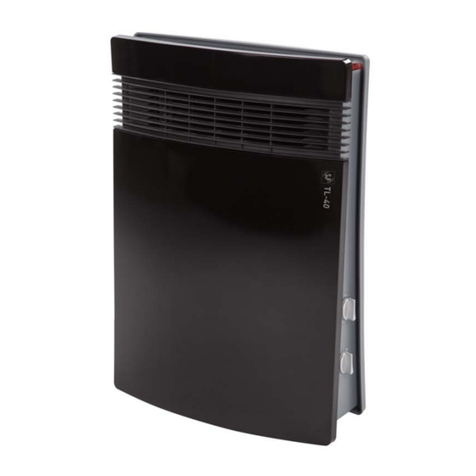
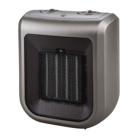
S&P CB-2002 User manual

Instrucciones de montaje y uso
Intallation and operating instructions
Prescriptions de montage et mode d’emploi
Instruçoes para montagem e utilizaçao
Installatie-en gebruiksaanwijzing
CALEFACTOR DE BAÑO
BATHROOM FAN HEATER
RADIATEUR SOUFFLANT POUR SALLES DE BAINS
AQUECEDOR DE QUARTO DE BANHO
BADKAMERVERWARMER
CB-2002
CB-2002T
Pol. Industrial Llevant
c/ Llevant 4
08150 Parets del Vallès (Barcelona)
ESP Ñ
Tel. 93 571 93 00
Fax 93 571 93 01
Tel. int. + 34 93 571 93 00
Fax int. + 34 93 571 93 11
http://www.solerpalau.com

Fig. 1
Fig. 2
Fig. 3
300 mm
1
Min. 100 mm
300 mm
300 mm
300 mm
300 mm
300 mm
800 mm 1000 mm
Sin accesorio toallero
Without towl rail accessory
Sans porte-serviette
Sem acessório toalheiro
Zonder handdoekhouder
Con accesorio toallero
With towl rail accessory
Avec porte-serviette
Com acessório toalheiro
Zonder handdoekhouder
Distancias mínimas
Minumum distances
Distances minimales
Distâncias mínimas
Montage afstanden
1 m
1 m
A
B
A Zona de protección
Protection zone
Volume de protection
Zona de protecção
Toegestane zone
B Zona de prohibición
Forbidden zone
Volume d’interdiction
Zona de proibição
Niet toegestane zone
BELANGRIJK: De garantie vervalt als alle reparaties of werkzaamheden aan
het apparaat uitgevoerd zijn door een persoon of personen die door S&P niet
erkend is/zijn.
Soler & Palau behoudt zich het recht voor wijzigingen in de specificaties aan
te brengen zonder kennisgeving vooraf.
28

is dan +5°C, wordt het apparaat automatisch ingeschakeld zodat de
temperatuur constant blijft. Dit antivrieselement is zeer nuttig op plaatsen
waar lage temperaturen normaal zijn en waar leidingwater gemakkelijk bevriest.
AUTOMATISCH WERKEND OVERVERHITTINGSELEMENT
Beide CB types beschikken over een ingebouwd oververhittingselement.
Deze beveiliging schakelt de verwarmingsunit automatisch uit als het apparaat
oververhit raakt. Als dit gebeurt dient u het volgende te doen:
- Haal de stekker uit het stopcontact.
- Laat het apparaat 10-15 minuten afkoelen.
- Wees er zeker van de luchtinlaat- en uitlaatroosters niet geblokkeerd zijn.
Verwijder elk voorwerp dat deze roosters blokkeert. Gebruik een stofzuiger
om het stof of vuil te verwijderen.
- Steek de stekker van het apparaat weer in het stopcontact en controleer de
werking.
Als, nadat u bovenstaande stappen uitgevoerd hebt, het apparaat niet werkt
haal dan de stekker uit het stopcontact en neem contact op met de technische
dienst van S&P.
ONDERHOUD
BELANGRIJK: VOORDAT U ONDERHOUD PLEEGT OF HET APPARAAT
REINIGT DIENT U EERST DE STEKKER UIT HET STOPCONTACT TE
VERWIJDEREN.
De verwarmingsunits, type CB, van S&P vereisen geen speciaal onderhoud.
Om er zeker van te zijn dat u langdurig en klachtenvrij het apparaat kunt
gebruiken raden wij u aan de luchtinlaat- en luchtuitlaatkanalen periodiek te
controleren op stof of op ander vuil. TIP: eerst het apparaat uitschakelen en
vervolgens met een stofzuiger het stof of het vuil uit de inlaat- en uitlaatkanalen
wegzuigen.
Maak het apparaat met een vochtige doek (niet met een natte doek) schoon.
Gebruik geen schuurmiddelen of oplosmiddelen.
SERVICE TECHNISCHE DIENST
Alle S&P wandgemonteerde CB verwarmingsunits worden geleverd met één
uitgebreide garantie.
Als het apparaat binnen de garantietermijn defect raakt, neem dan onmiddellijk
contact op met onze technische dienst en stuur het apparaat, indien
noodzakelijk, op naar een erkende S&P leverancier.
27
2
235 mm
357,5 mm
3 mm
Interruptor / Conmutador
On / Off Switch - Power Selector
Interrupteur / Commutadeur
Interruptor / Comutador
Aan/uit schakelaar
Termostato
Thermostat / Heat Control
Thermostat
Termóstato
Thermostaat
Interruptor / Termostato
Thermostat
Interrupteur / Thermostat
Interruptor / Termóstato
Thermostaat
Temporizador
Timer
Minuterie
Temporizador
Tijdschakelaar
CB-2002T
CB-2002
Fijación
Fixing to wall
Fixation
Fixação
Montagebeugel
Fig. 4
Fig. 5
Fig. 6

Fig. 7
Marrón
Brown
Brun
Castanho
Bruin
Azul
Blue
Blue
Azul
Blauw
3
230 V~
N
L
Fig. 8
temperatuur constant blijft. Dit antivrieselement is zeer nuttig op plaatsen
waar lage temperaturen normaal zijn en waar leidingwater gemakkelijk bevriest.
Bediening van type CB-2002T (Afb.6)
Aan/Uit & thermostaat keuzeschakelaar
0=Uit
= 1000 W
( ) = Antivriesbescherming & laagste stand van de
thermostaat
( ) = Hoogste stand van de thermostaat
1. Zorg er voor dat de tijdschakelaar op stand (0) staat.
2. Draai de keuzeschakelaar van de thermostaat naar de hoogste stand.
3. Dit apparaat werkt bij een standaard output van warmte van 1000 W. De
stroomtoevoer en de werking worden door middel van een klein neonlichtje
aangegeven.
4. Als het apparaat voor het eerst ingeschakeld wordt dan zal de
omgevingstemperatuur dienovereenkomstig veranderen. Als de gewenste
omgevingstemperatuur bereikt is, draai dan de keuzeschakelaar van de
thermostaat terug totdat u een klikgeluid hoort. Het apparaat staat nu uit. Als
de thermostaat op deze stand staat, schakelt het apparaat automatisch aan
en uit om de gewenste temperatuur te behouden.
TIJDSCHAKELAAR
0= Uit
(5-60) = Instelbaar tussen 5-60 min. Stel de tijd in dat het apparaat in
werking moet zijn met behulp van de tijdschakelaar. Als u de tijdschakelaar
gebruikt, is de output van de warmte 1800 W en werkt onafhankelijk van de
thermostaatschakelaar. Dus als u de tijdschakelaar gebruikt, is de thermostaat
buiten werking. Als de ingestelde tijd verstreken is zal het apparaat werken op
1000 W door middel van de thermostaatschakelaar.
AUTOMATISCHWERKEND VORSTBEVEILIGING CB-2002T
De CB-2002T wandgemonteerde verwarmingsunit is uitgerust met een
antivrieselement dat automatisch in werking treedt als de temperatuur lager
is dan +50C. Om dit element te activeren als het apparaat niet in werking is
dient u de Aan/Uit keuzeschakelaar op stand I of II te zetten en vervolgens de
keuzeschakelaar van de thermostaat op stand ( ). Als de temperatuur lager
26
*
*

1. Alle elektrische aansluitingen dienen door een erkend vakman uitgevoerd
te worden.
2. Alle elektrische aansluitingen dienen overeenkomstig landelijke en plaatselijke
elektrische regelgeving gemaakt te worden.
3. Het is de verantwoordelijkheid van de installateur om de juiste zekering en/
of uitschakelmechanisme aan te brengen om elektrische storingen te
voorkomen.
BEDIENING
Bediening van type CB-2002 (afb.5)
Aan/Uit & keuzeschakelaar.
0=Uit
I= 1000W
II = 1800W
Thermostaat keuzeschakelaar
( ) = Bescherming tegen bevriezing & laagste stand van de
thermostaat
( ) = Hoogste stand van de thermostaat
1. Draai de keuzeschakelaar van de thermostaat naar de hoogste stand.
2. Kies het gewenste vermogen, 1000 of 1800 W. De stroomtoevoer en de
werking worden aangeduid door het kleine neonlichtje.
3. Als het apparaat voor de eerste keer ingeschakeld wordt, zal de omgeving
dienovereenkomstig verwarmd worden. Is de gewenste
omgevingstemperatuur bereikt, draai dan de keuzeschakelaar van de
thermostaat terug totdat u een klikgeluid hoort. Het apparaat staat nu uit.
Als de thermostaat op deze stand staat, schakelt het apparaat automatisch
aan en uit om de gewenste constante temperatuur te behouden.
AUTOMATISCHWERKEND
VORSTBEVEILIGING CB-2002
De CB-2002 wandgemonteerde verwarmingsunit is uitgerust met een
antivrieselement dat automatisch in werking treedt als de temperatuur lager
is dan +50C. Om dit element te activeren als het apparaat niet in werking is
dient u de Aan/Uit keuzeschakelaar op stand I of II te zetten en vervolgens de
keuzeschakelaar van de thermostaat op stand ( ). Als de temperatuur lager
wordt dan +5°C, zal het apparaat automatisch inschakelen zodat de
25
*
*
ESPAÑOL
GENERAL
Le agradecemos la confianza que nos ha depositado mediante la compra de
este aparato. Usted ha adquirido un producto de calidad que ha sido
totalmente fabricado según reglas técnicas de seguridad reconocidas y
conformes a las normas de la CE.
Sírvase leer atentamente estas instrucciones, antes de la puesta en funciona-
miento y guárdelas para futuras referencias.
Rogamos compruebe el perfecto estado y funcionamiento del aparato al
desembalarlo ya que cualquier defecto de origen que presente está ampara-
do por la garantía S&P
INSTRUCCIONES IMPORTANTES
ADVERTENCIAS DE SEGURIDAD
Este aparato es de doble aislamiento ( ) y puede instalarse en cualquier
habitación o dependencia de la casa ( baño, cocina, etc.). No obstante deben
observarse las siguientes precauciones:
- Si se instala de forma fija en el cuarto de baño, deberá colocarse de manera
que los interruptores y otros dispositivos de mando no puedan ser tocados
por una persona que esté en la bañera o en la ducha.
- El aparato puede instalarse dentro de la zona de protección pero siempre
que la toma de corriente este situada fuera de dicha zona (Fig.1).
- El calefactor no debe estar situado justamente debajo de una base de toma
de corriente.
- Al instalarse de forma fija, también deberán respetarse las distancias
mínimas indicadas en la Fig. 2.
- Siempre que se instale de forma fija, el aparato deberá estar situado de forma
que el interruptor o la clavija sean accesibles.
- La conexión fija solamente podrá efectuarse en redes de cables que estén
equipadas con un dispositivo de separación omnipolar con una apertura de
contactos de 3mm como mínimo en todos los polos.
- Si el cable flexible de alimentación está dañado, debe ser sustituido en uno
de nuestros Talleres de Reparación o por personal similar cualificado con el
fin de evitar un peligro.
- No cubrir el calefactor con objetos que impidan la libre circulación del aire.
Si se cubre existe el riesgo de sobrecalentamiento.
4

- Mientras esté en funcionamiento, el cable no deberá estar en contacto con
la zona caliente del aparato.
- No manipular con las manos mojadas.
- Mantenga limpias las entradas y salidas del aire. Siempre que realice la
limpieza, tenga la precaución de desconectar el aparato.
INSTALACIÓN
MONTAJE EN LA PARED
Habiendo decidido las distancias mínimas según la Fig.2, instale el aparato
siguiendo la secuencia siguiente :
1. Marque la situación de los agujeros superiores, según el dibujo de la Fig.4.
Efectúe los taladros.
2. Fije los tornillos dejando 3 mm de separación entre la pared y la cabeza de
los mismos.
3. Cuelgue el aparato de las ranuras existentes en la parte posterior. Marque
el agujero de fijación inferior. Descuelgue el aparato y efectúe el correspon-
diente taladro.
4. Cuelgue el aparato y fíjelo mediante el tornillo inferior.
Se suministra aparte, un accesorio para colgar toallas. Se fijará al calefac-
tor según dibujo de la Fig.3. Deberá procurarse de no obstruir la salida del
aire, respetando la distancia mínima indicada.
CONEXIÓN ELÉCTRICA
Nuestros calefactores se entregan con cable flexible y clavija.
Al tratarse de aparatos de clase II (Doble aislamiento) no necesitan estar
conectados a la red de puesta a tierra de la instalación.
Compruebe que la tensión de la red coincida con la indicada en la placa de
características.
Si quiere conectar de forma fija el cable de conexión a la red, deberá observar
el esquema de conexiones (Fig.7) y respetar las siguientes disposiciones:
1. La conexión fija deberá efectuarla un profesional.
2. En su conexionado a la red, deberán tenerse en cuenta las directrices que
se indican en el Reglamento de Baja Tensión y las propias de cada país.
3. Debe preveerse en la instalación un interruptor magnetotérmico u otro
dispositivo de desconexión omnipolar que interrumpa todas las líneas de
alimentación al aparato.
5
- Het apparaat dient d.m.v. voedingskabels met de juiste afmetingen
aangesloten te worden.
- Alle installatiewerkzaamheden dienen uitgevoerd te worden overeenkomstig
alle van toepassing zijnde landelijke en plaatselijke installatievoorschriften.
- Haal altijd de stekker uit het stopcontact voordat u het apparaat reinigt of
onderhoud pleegt. De enige plaatsen op het apparaat die reiniging behoeven
zijn de luchtinlaat en de luchtuitblaas.
- In de elektrische schakeling moet een tweepolige schakelaar met ten minste
3 mm contactafstand voorkomen.
INSTALLATIE
MONTEREN VAN DE CB VERWARMINGSUNIT AAN DE MUUR
Als u een geschikte plaats voor het apparaat gevonden hebt overeenkomstig
de aanbevelingen (zie afb.2) en de veiligheidsvoorschriften, dient het apparaat
volgens onderstaande volgorde gemonteerd te worden:
1. Markeer eerst de boorgaten en boor vervolgens gaten voor de bovenste
twee bevestigingsschroeven zoals aangegeven op afb.4. Plaats pluggen.
2. Draai de beide schroeven vast en laat daarbij ongeveer 3mm ruimte tussen
de muur en de schroefkoppen.
3. Bevestig het apparaat op deze twee schroeven en markeer vervolgens het
boorgat van de onderste schroef. Verwijder het apparaat en boor vervolgens
het gat en plaats de plug.
4. Bevestig het apparaat aan de twee bovenste schroeven en stel het apparaat
met behulp van de onderste schroef.
Het apparaat is standaard uitgerust met een handdoekrail. Als u dit accessoire
wilt gebruiken dan dient het apparaat gemonteerd te worden zoals op afb.3
staat aangegeven. Het is belangrijk er zeker van te zijn dat het luchtuitlaatrooster
niet geblokkeerd wordt om verzekerd te zijn van een veilige en probleemloze
werking.
ELEKTRISCHE AANSLUITING
De verwarmingsunits van het CB type worden compleet geleverd met een
flexibel elektrisch snoer. Alle modellen vallen onder klasse II (dubbel geïsoleerd).
Daarom is aarding niet verplicht.
Voordat u de elektriciteit aansluit, wees er dan zeker van dat het voltage en de
frequentie van de elektriciteit overeenkomen met de gegevens die op het
typeplaatje vermeld staan.
De elektrische aansluitingen dienen gemaakt te worden overeenkomstig
afb.7 met aandacht voor de volgende punten:
24

DEUTCH
INSTRUCTIES
ALGEMEEN
De verwarmingsunits voor de badkamer uit de CB serie zijn volgens zeer
strenge productiekwaliteitsnormen vervaardigd overeenkomstig de
International Quality Standards. Alle onderdelen zijn aan het einde van het
productieproces gecontroleerd en getest.
Alvorens tot installatie en aansluiting over te gaan adviseren wij u de volgende
instructies goed door te lezen en goed te bewaren zodat ze steeds geraadpleegd
kunnen worden.
Alle apparaten worden in perfecte staat afgeleverd. Mochten er desondanks
mankementen zijn, dan dient u het apparaat overeenkomstig de S&P
garantiebepalingen naar uw leverancier terug te sturen.
BELANGRIJKE VEILIGHEIDSVOORSCHRIFTEN
Deze apparaten zijn dubbel geïsoleerd ( ) en kunnen veilig in zone 3 van
badkamers en toiletten geplaatst worden is. Voorafgaand aan de installatie
dienen de volgende veiligheidsvoorschriften nauwgezet opgevolgd te worden:
- Als het apparaat voor de badkamer bestemd is mag het nooit op een plaats
geïnstalleerd worden waarbij men gemakkelijk bij de schakelaars kan komen
tijdens het douchen of als men aan de wastafel staat.
- Plaats het apparaat altijd op een veilige plaats zoals op afb.1 is aangegeven.
- Plaats het apparaat nooit direct onder een stopcontact of een andere
elektrische aansluiting.
- Installeer het apparaat nooit op een muur of object dat bestaat uit ontvlambaar
materiaal (kunststof, hout, gordijnen e.d.).
- Installeer het apparaat overeenkomstig de minimum aanbevolen afstanden
tot andere apparaten of tot vaste objecten zoals aangegeven op afb.2.
- Bedien het apparaat nooit met natte handen.
- Bedek het apparaat nooit met voorwerpen die de luchtstroom belemmeren.
Installeer het apparaat altijd op een plaats waar een stopcontact makkelijk
bereikbaar is.
- Als de voedingskabel beschadigd is dient men die niet te gebruiken. Het
apparaat dient dan opgestuurd te worden naar een erkend leverancier of
dient door een erkend vakman gerepareerd te worden.
- Als het apparaat in werking is dient de voedingskabel verwijderd te zijn van
de warme luchtstroom.
23
6
PUESTA EN MARCHA Y FUNCIONAMIENTO
Funcionamiento del CB-2002 (Fig. 5 )
Mando interruptor/conmutador
0= Paro
I= 1000 W
II = 1800 W
Mando termostato
( ) = Posición antiheladas y mínima del termostato
( ) = Posición máxima del termostato
1. Gire el Mando Termostato hasta su posición máxima.
2. Seleccione la potencia 1000 ó 1800 W.
3. Una vez que la habitación haya alcanzado la temperatura deseada, gire
lentamente el Mando Termostato en sentido contrario a las agujas del reloj,
hasta que con un suave “clic” se desconecte el aparato.
A partir de este momento, el calefactor se conectará y desconectará
automáticamente, manteniendo constante la temperatura preseleccionada.
Con el conmutador en la posición I ó II la luz piloto permanecerá encendida
PROTECCIÓN ANTIHELADAS DEL CB-2002
El CB-2002 incorpora un dispositivo antiheladas que hace que el aparato se
ponga en funcionamiento cuando la temperatura ambiente desciende de
+5°C. Para accionar este dispositivo basta con conectar el aparato a la red,
colocar el Mando “Interruptor/Conmutador” en su posición ( I ) o ( II ) y el
Mando Termostato en la posición ( ). El aparato quedará desconectado, pero
si la temperatura ambiente desciende de +5°C automáticamente se pondrá
en funcionamiento manteniendo una temperatura ambiental de +5°C. Este
dispositivo es especialmente beneficioso en lugares donde se alcanzan bajas
temperaturas y es fácil que se hiele el agua de las tuberías, etc..
Funcionamiento del CB-2002T (Fig. 6)
Mando Interruptor/Termostato
0= Paro del aparato
= Posición 1000 W
( ) = Posición antiheladas y mínima del termostato
( ) = Posición máxima del termostato
*
*
*

7
Puesta en marcha del CB-2002T
- Posición del Mando Temporizador = 0
- Posición Mando Interruptor/Termostato en su posición máxima
El aparato funcionará a 1000W y cuando la temperatura ambiente haya
alcanzado la temperatura máxima deseada, gire el Mando Interruptor/Ter-
mostato en sentido contrario a las agujas del reloj, hasta que con un suave
“clic” se desconecte el aparato.
A partir de este momento no será necesario volver a manipular el Mando
Termostato ya que el aparato se conectará y desconectará automáticamente
para mantener constante la temperatura preseleccionada.
Con el conmutador en la posición • la luz piloto permanecerá encendida.
Mando Temporizador
0= Paro del temporizador
Zona reglada de 5 a 60 minutos = Seleccione el tiempo deseado con la
ayuda del temporizador. El aparato funcionará a 1800 W durante dicho tiempo
e independientemente de la situación del mando interruptor/termostato.
Mientras funciona el temporizador, el termostato queda inoperante. Una vez
transcurrido el tiempo seleccionado, el aparato funcionará a 1000 W contro-
lado por el termostato
PROTECCIÓN ANTIHELADAS DE CB-2002T
El CB-2002T incorpora un dispositivo antiheladas que hace que el aparato se
ponga en funcionamiento cuando la temperatura ambiente desciende de
+5°C. Para accionar este dispositivo basta con conectar el aparato a la red,
colocar el Mando Temporizador en 0y el Mando Interruptor/Termostato en la
posición ( ). El aparato quedará desconectado, pero si la temperatura
ambiente desciende de +5°C automáticamente se pondrá en funcionamiento
manteniendo una temperatura ambiental de +5°C. Este dispositivo es espe-
cialmente beneficioso en lugares donde se alcanzan bajas temperaturas y es
fácil que se hiele el agua de las tuberías, etc.
DESCONEXIÓN POR SOBRECALENTAMIENTO
Si se produjera alguna perturbación, el sistema de desconexión por
sobrecalentamiento desconecta automáticamente el aparato. Si esto ocurre:
- Desconecte el aparato de la red.
- Deje enfriar el aparato durante unos 15 minutos.
- Revise que no estén obstruidas las rejillas de entrada y salida del aire por
partículas de polvo. Si fuera necesario, límpielas con un aspirador.
*
- Verifique se as grelhas de entrada e saída do ar não estão obstruídas por
poeiras. Se for necessário, limpe-as com um aspirador.
Se depois destas operações o aparelho não funcionar normalmente, deve-se
recorrer aos serviços de assistência “S&P”.
MANUTENÇÃO
Estes aparelhos não precisam de nenhuma manutenção especial. Antes de
proceder-se à sua limpeza, desligá-los da rede eléctrica. Espere que a
carcaça arrefeça e limpe-a com um pano macio, impregnado com um
detergente não abrasivo.
Utilize um aspirador para limpar as grelhas de entrada e de saída do ar.
ASSISTÊNCIA TÉCNICA
No caso do aparelho ter qualquer anomalia, deve entregar o aparelho onde
o adquiriu, para ser enviado aos nossos Serviços Técnicos. Qualquer
manipulação do aparelho por pessoas estranhas aos nossos serviços técni-
cos, fará cessar a garantia.
22

Si después de estos controles el aparato no funciona normalmente, le
rogamos que acuda a la amplia red de Servicios Oficiales S&P.
MANTENIMIENTO
Los calefactores S&P no necesitan de un especial mantenimiento. Antes de
proceder a su limpieza no olvide desconectar el aparato de la red. Espere que
la carcasa se enfríe y límpiela con un paño suave impregnado con un
detergente no abrasivo.
Utilice un aspirador para limpiar las rejillas de entrada y salida del aire.
ASISTENCIA TÉCNICA
La extensa Red de Servicios Oficiales S&P garantiza una adecuada asistencia
técnica. En caso de observar alguna anomalía en el aparato, rogamos se
ponga en contacto con cualquiera de los servicios mencionados, donde será
debidamente atendido. Cualquier manipulación efectuada por personas
ajenas a los Servicios Oficiales S&P, nos obligaría a cancelar su garantía.
8
Ligar o CB-2002T
- Posição do Comando Temporizador = 0
- Posição do Comando Interruptor/Termóstato na sua posição máxima.
O aparelho funcionará a 1000 W e quando a temperatura ambiente alcançar
a temperatura máxima desejada, rode o Comando Interruptor/Termóstato no
sentido contrário ao dos ponteiros do relógio, até que, com um suave “clique”
, o aparelho se desliga.
A partir deste momento, não será necessário voltar a mexer no Comando do
Termóstato já que aquecedor ligará e desligará automaticamente, mantendo
constante a temperatura pré-seleccionada.
Com o comutador na posição a luz piloto permanecerá acesa.
Comando do Temporizador
0=Temporizador parado
Zona regulada de 5 a 6 minutos = Seleccione o tempo desejado, com a ajuda
do temporizador. O aparelho funcionará a 1800 W durante o dito tempo e,
independentemente, do Comando Interruptor/Termóstato. Quando funciona
o temporizador, o termóstato fica inoperante. Uma vez transcorrido o tempo
seleccionado, o aparelho funcionará a 1000 W controlado por termóstato.
PROTECÇÃO ANTI-GELO DO CB-2002T
O CB-2002T incorpora um dispositivo anti-gelo que faz com que o aparelho
entre em funcionamento quando a temperatura ambiente desce dos +5º C.
Para accionar tal dispositivo, basta ligar o aparelho à rede eléctrica, colocan-
do o Comando Temporizador em 0e o Comando “Interruptor/Termóstato”
na posição ( ).O aparelho permanecerá desligado, mas se a temperatura
ambiente descer dos + 5 º C., ligar-se-à automaticamente, mantendo uma
temperatura ambiente de +5º C .Este dispositivo é, especialmente, benéfico
em locais de baixas temperaturas e onde, facilmente, a água gela nos canos,
etc.
DESLIGAMENTO POR SOBREAQUECIMENTO
Se houver qualquer perturbação, o sistema de sobreaquecimento incorpora-
do, desliga automaticamente o aparelho. Se isto suceder :
- Desligue o aparelho da rede eléctrica.
- Deixe-o arrefecer durante uns 15 minutos.
21
*

LIGAÇÃO E FUNCIONAMENTO
Funcionamento do CB-2002 (Fig.5)
Comando interruptor/comutador
0= Parado
I= 1.000 W
II = 1.800 W
Comando do termóstato
( ) Posição anti-gelo e mínima do termóstato.
( ) Posição máxima do termóstato.
1. Rode o comando do termóstato até à sua posição máxima.
2. Seleccione a potencia 1000 ou 1800 W.
3. Uma vez alcançada a temperatura máxima desejada para o local, rode
lentamente o Comando do termóstato no sentido contrário aos dos ponteiros
do relógio, até que, com um suave “clique” , o aparelho se desliga.
A partir deste momento, o aquecedor ligará e desligará automaticamente,
mantendo constante a temperatura pré-seleccionada.
Com o comutador na posição I ou II a luz piloto permanecerá acesa.
PROTECÇÃO ANTI-GELO DO CB-2002
O CB-2002 incorpora um dispositivo anti-gelo que faz com que o aparelho
entre em funcionamento quando a temperatura ambiente desce dos +5º C.
Para accionar tal dispositivo, basta ligar o aparelho à rede eléctrica, colocan-
do o Comando “Interruptor/Comutador” na sua posição I ou II e o Comando
do Termóstato na posição ( ).O aparelho permanecerá desligado, mas se a
temperatura ambiente descer dos + 5 º C., ligar-se-à automaticamente,
mantendo uma temperatura ambiente de +5º C .Este dispositivo é, especial-
mente, benéfico em locais de baixas temperaturas e onde, facilmente, a água
gela nos canos, etc.
Funcionamento do CB-2002T (Fig.6)
Comando interruptor/termóstato
0 = Parado
= 1.000 W
( ) = Posição anti-gelo e mínima do termóstato
( ) = Posição máxima do termóstato
20
*
*
*
ENGLISH
USER INSTRUCTIONS CB-2002 / CB-2002T
GENERAL.
The CB range of bathroom heaters have been manufactured to the rigorous
standards of production quality laid down by the International Quality Standards.
All components have been checked and tested at the end of the manufacturing
process.
Before any installation or connection we would advise that the following
instructions are carefully read and then kept in an accessible area for future
reference.
All appliances are supplied in perfect condition and operation. However if
found to be defective the unit should be returned to the supplier in accordance
with ther terms of the S&P guaranttee.
IMPORTANT SAFETY NOTES
These appliances are supplied as double insulated appliances ( ) and they
can be safely installed within resisdential environments (bathroom, kitchens)
depending upon the suitablity of the intended location. Before installation the
following important precausions should be observed:
- If the appliance is intended to be installed in a bathroom, it must not be
installed where a person could reach any of the switches and controls, when
standing / sitting within the bath or shower or near a wash basin.
- We would reccommend, where possible, that the unit is installed outside the
Zone of protection, as illustrated in Figure (1).
- The appliance must not be sited directly under an electrical connection
socket or similar device.
- Do Not site the appliance by the side of a wall / object constructed from
combustible materials (plastic, wood, curtains etc).
- The appliance must be installed in accordance with the minimum
reccomended distances from other appliances / fixed objects as detailed in
Figure (2).
- Do Not Operate This Appliance With Wet Hands.
- Do Not Cover the appliance with objects which would restrict the flow of air.
- The appliance should always be installed where the the mains electrical
switch socket connection is accessible.
- If the electrical supply cable is found to be damaged then the appliance Must
Not Be Used. The appliance must be returned to an authorised supplier or
repaired by a suiatbly qualified person.
9

10
- When the appliance is operating, the electrical supply cable should be routed
away from the flow of heated air.
- The appliance should be connected to the electrical supply with correctly
sized cables and should include a double pole switch with a contact
clearance of at least 3mm.
- All installation work should be carried out in accordance with all applicable
National and Local Building Code Regulations pertaining to the country of
installation.
- Before any cleaning or maintenance the appliance must be disconnected
and isolated from the mains electrical supply. The only areas on the
appliance that require cleaning (only wipe with a damp not wet cloth) are the
intake and extract air vents.
INSTALLATION
Mounting the CB Heaters to a wall.
Having located a suitable position of mounting for the unit, in accordance with
the recommendations in Figure (2) and the Important Safety Notes, the
appliance should be installed in the following sequence:
1. Mark and drill holes for the top two screw fixing positions, as in Figure (4).
Insert raw-plugs or similar to secure the screws.
2. Insert the top two (2) screws into the wall, leaving approximately 3mm gap
between the wall and screw face.
3. Mount the appliance onto these two screws then mark the position of the
bottom screw fixing. Remove the appliance and drill a corresponding hole and
insert a raw-plug.
4. Enguage the appliance on the top two screws and secure in position with
the third bottom screw.
As an accesory, there is the possibility to install a Tower Rail in the appliance.
If this accessory is intended to be used, then the appliance must be installed
in accordance with Figure (3). It is important to ensure that the air discharge
grill is not obstructed to provide safe and trouble free operation.
ELECTRICAL CONNECTION
The CB range of heaters are supplied complete with an flexible electrical cord.
All models incorporate Class II (double insulation). Therefore no earth
connection is required.
Before making electrical connection, ensure that the Voltage and Frequency
of the electrical supply matches that of the appliance data plate label.
The electrical connections should then be made in accordance with Figure (7),
- Quando em funcionamento, o cabo de ligação não deve estar em contacto
com a zona de aquecimento.
- Não lhe mexer com as mãos molhadas.
- Manter limpas as grelhas de entrada e saída do ar.Sempre que se fizer uma
limpeza, desligar o aparelho da rede de alimentação eléctrica.
- Quando o aparelho está a trabalhar evitar ter objectos inflamáveis a menos
de 50 cm do circuito de ar quente (cortinas ,etc...).
INSTALAÇÃO
MONTAGEM NA PAREDE
Decididas as distâncias mínimas segundo a Fig.2., instale o aparelho confor-
me a sequência seguinte :
1. Marque a situação dos buracos superiores, segundo o desenho da Fig.4.
Faça os furos.
2. Fixe os parafusos, deixando 3 mm de separação entre a parede e a cabeça
dos mesmos.
3. Pendure o aparelho nas ranhuras existentes na parte superior. Marque o
buraco de fixação inferior. Retire o aparelho e faça o correspondente furo.
4. Dependure o aparelho e fixe-o, mediante o parafuso inferior.
Fornece-se, à parte, um acessório para pendurar toalhas. Fixa-se aquele ao
aparelho, conforme o desenho da Fig.3.Deve procurar-se não obstruir a saída
do ar, respeitando a distância mínima indicada.
LIGAÇÃO ELÉCTRICA
Os nossos aquecedores são fornecidos com cabo flexível e ficha.
Por se tratar de aparelhos da classe II (Duplo isolamento) não precisam de
ligação à terra.
Comprove que a tensão da rede coincide com a da placa de características.
Se quer ligar , de forma fixa, o cabo de ligação à rede, deverá observar o
esquema de ligações (Fig.7) e respeitar as disposições seguintes :
1. A ligação deverá ser feita por um profissional
2. Na ligação à rede deverá ter-se em conta as directivas indicadas no
Regulamento de Baixa Tensão.
3. Deve prever-se, na instalação, um interruptor magnetotérmico ou outro
dispositivo de desligamento omnipolar que interrompa todas as linhas de
alimentação ao aparelho.
19

18
PORTUGUES
INSTRUÇÕES CB-2002/CB-2002T
GERAL
Agradecemos a confiança demonstrada na compra deste aparelho. Adquiriu
um produto de qualidade, totalmente fabricado segundo reconhecidas
regras técnicas de segurança e conforme as normas CE.
Leia atentamente estas instruções antes de utilizar o aparelho, guardando-as
para futuras consultas.
Depois de desembalar o aparelho, verificar o seu estado e funcionamento,
pois qualquer defeito de origem está coberto pela garantia “S&P”
INSTRUÇÕES IMPORTANTES
RECOMENDAÇÕES DE SEGURANÇA
Este aparelho é de isolamento duplo ( ) e pode ser instalado em qualquer
habitação ou dependência da casa (quarto de banho, cozinha, etc.) Não
obstante, devem observar-se as precauções seguintes :
- Se for instalado de forma fixa no quarto de banho, deverá colocar-se de
maneira que os interruptores e outros dispositivos de comando não possam
ser tocados pela pessoa que estiver na banheira ou no duche.
- O aparelho pode instalar-se dentro da zona de protecção, mas sempre que
a tomada de corrente esteja colocada fora da dita zona (Fig.1).
- O aquecedor não deve estar colocado justamente debaixo de uma tomada
de corrente .
- Ao instalar-se de forma fixa, também deverão respeitar-se as distâncias
mínimas indicadas na Fig.2
- Sempre que se instale o aparelho de forma fixa, deverá ficar colocado de
maneira a que o interruptor ou a ficha fiquem acessíveis.
- A ligação fixa somente poderá fazer-se a redes de cabos que estejam
equipados com um dispositivo de separação omnipolar, com uma abertura
de contactos de 3 mm, como mínimo em todos os pólos.
- Se o cabo de ligação estiver danificado, somente poderá ser substituído por
outro nos nossos Serviços Técnicos ou por pessoal qualificado, de maneira
a evitarem-se situações perigosas.
- Não o cobrir com objectos ou móveis que impeçam a livre circulação do ar,
pois se o fizer há o perigo de sobreaquecimento.
11
with reference to the following:
1. All electrical connections should be carried out by a suitably qualified
person(s)
2. All electrical connections should be in accordance with all applicable
National and Local Electrical Codes Of Practice.
3. It is the responsibility of the installer to include a suitable fuse / trip device
to isolate the appliance upon detection of an electrical surge or faliure.
OPERATION
Operation of Model CB-2002 (Fig.5)
ON /OFF & Power Selector Switch.
0= OFF
I= 1000W
II = 1800W
Thermostat Control Selector Switch
( ) = Frost Protector & Minimum Thermostat Position
( ) = Maximum Thermostat Position
1. Turn the Thermostat Control Switch to the maximum position.
2. Select the desired heat output, 1000 or 1800W. Indication of power supply
and operation is provided by the illumination of the small neon light.
3. The first time the unit is switched ON, the surrounding environment will heat
up accordingly. When the desired temperature of the environment has been
reached, turn the Thermostat Selector Switch down until a “click” is heard.
The unit will switch OFF.
When the thermostat is in this position the appliance will automatically switch
ON and OFF to maintain this desired temperature.
Automatic anti-frost Device CB-2002
The CB-2002 wall mounted heater incorporates as standard an Anti-Frost
Protection Device which switches the unit ON automatically when the
temperature is less than +50C. To activate this device when the heater is not
in use, simply turn the Power Selector switch to position (I) or (II) and then turn
the Thermostat to position ( ). Therefore when the temperature drops below
*
*

12
+50C the appliance will automatically switch ON keeping the room at this
constant temperature. This device is very useful where low temperatures are
common and where pipeline water is easily frosted.
Operation of Model CB-2002T (Fig.6)
ON /OFF & Thermostat Selector Switch.
0= OFF
= 1000W
( ) = Frost Protector & Minimum Thermostat Position
( ) = Maximum Thermostat Position
1. Ensure the Timer Switch is in the position (0).
2. Turn the Thermostat Selector Switch to maximum position.
3. This appliance operates at a 1000W heat output as standard. Indication of
power supply and operation is provided by the illumination of the small neon
light.
4. The first time the unit is switched ON, the surrounding environment will heat
up accordingly. When the desired temperature of the environment has been
reached, turn the Thermostat Selector Switch down until a “click” is heard.
The unit will switch OFF.
When the thermostat is in this position the appliance will automatically switch
ON and OFF to maintain this desired temperature.
Timer switch
0= Position OFF
Regulate between 5 –60 mins. = Select the operation time required by
turning the Timer Switch accordingly. When using the Timer, the heat output
is 1800W, and operates independantly from the Thermostat Switch. Therefore
when using the Timer function the Thermostat will not operate. When the
Timer period has elapsed, the appliance will revert back to the operation at
1000W via the Thermostat Switch.
AUTOMATIC ANTI-FROST DEVICE CB-2002T
The CB-2002T wall mounted heater incorporates as standard an Anti-Frost
Protection Device which switches the unit ON automatically when the
temperature is less than +50C. To activate this device when the heater is not
in use, simply ensure the Timer Switch switch is at position 0, and then turn
the Thermostat to position ( ). Therefore when the temperature drops below
*
*
17
La commande de la minuterie sélectionne le temps de fonctionnement du
radiateur soufflant en puissance maximale
0= Minuterie arrêtée
Plageentre 0et60= Le radiateur fonctionne à 1800W le temps présélectionné
et indépendamment de la position de l’interrupteur/thermostat. Le thermostat
est inopérant. Une fois écoulé le temps fixé par la minuterie, le radiateur
soufflant fonctionnera de nouveau à 1000W, commandé par le thermostat.
Dispositif «hors gel»
Les radiateurs soufflants CB-2002T incorporent un dispositif “hors gel”
mettant en marche automatiquement le radiateur quand la température
ambiante descend en deçà de +5ºC et pour la maintenir à ce niveau.
Ce dispositif est particulièrement intéressant pour les lieux où le gel pourrait
causer des problèmes pour les conduites d’eau.
Une fois raccordé au réseau, pour mettre en action ce dispositif il suffit de
placer l’interrupteur/thermostat sur la position ( ) et la minuterie sur 0.
Dispositif de sécurité contre les surchauffes
Les radiateurs soufflants sont équipés d’une protection thermique arrêtant
automatiquement l’appareil en cas de surchauffe.
Au cas où cela se produirait, débrancher l’appareil, laisser le refroidir 15
minutes, vérifier que les grilles de soufflage et d’aspiration ne soient pas
obstruées par une accumulation de poussières; éventuellement les nettoyer
avec un aspirateur.
Si le problème persiste, mettez-vous en contact avec votre distributeur.
Entretien
Les convecteurs soufflants CB-2002 et 2002T ne nécessitent aucun entretien
particulier si ce n’est un nettoyage régulier. Avant toutes opérations d’entretien,
débrancher le radiateur soufflant et attendre son refroidissement complet.
Nettoyer la carcasse avec un chiffon doux et les grilles d’entrée et de soufflage
d’air avec un aspirateur.
Ne pas immerger l’appareil ni le placer sous un robinet d’eau.
Ne jamais utiliser de produits abrasifs ou des solvants.
Ne pas démonter l’appareil, toutes manipulations effectuées par une personne
non autorisée, entraîneraient l’annulation de la garantie.
Nota:Il est très important d’entretenir régulièrement un radiateur soufflant. La
négligence de cet entretien pourrait provoquer un incendie
*

16
1. Tourner la commande du thermostat jusqu’à sa position maximale
2. Placer l’interrupteur/commutateur sur la position ( I) ou ( II ).
3. Quand la température, dans la pièce à chauffer, aura atteint le niveau désiré,
tourner la commande du thermostat en sens inverse des aiguilles d’une
montre, jusqu’à ce que s’entende un léger «clic». Laissant le thermostat sur
cette position, le radiateur soufflant maintiendra la température ainsi
sélectionnée en se mettant en marche et en s’arrêtant automatiquement.
Quand l’interrupteur/commutateur est placé sur la position ( I) ou ( II ), le
témoin lumineux est allumé.
DISPOSITIF «HORS GEL»
Les radiateurs soufflants CB-2002 incorporent un dispositif “hors gel” mettant
en marche automatiquement le radiateur quand la température ambiante
descend en deçà de +5ºC et pour la maintenir à ce niveau.
Ce dispositif est particulièrement intéressant pour les lieux où le gel pourrait
causer des problèmes pour les conduites d’eau.
Une fois raccordé au réseau, pour mettre en action ce dispositif il suffit de
placer l’interrupteur/commutateur sur la puissance désirée ( I ) ou ( II ) et le
thermostat en position ( ).
CB-2002T (FIG.6)
L’interrupteur/thermostat sélectionne les positions suivantes:
0= Arrêt
= 1000 W
( ) = Dispositif «hors gel»
( ) = Position maximum du thermostat
Laisser la commande de la minuterie sur la position 0et placer le thermostat
en position maximale.
Le radiateur soufflant fonctionnera à 1000W. Quand la température, dans la
pièce à chauffer, aura atteint le niveau désiré, tourner la commande du
thermostat en sens inverse des aiguilles d’une montre, jusqu’à ce que
s’entende un léger «clic». Laissant le thermostat sur cette position, le
convecteur soufflant maintiendra la température ainsi sélectionnée en se
mettant en marche et en s’arrêtant automatiquement.
Quand l’interrupteur/thermostat est placé sur la position l, le témoin lumineux
est allumé.
*
*
13
+50C the appliance will automatically switch ON keeping the room at this
constant temperature. This device is very useful where low temperatures are
common and where pipeline water is easily frosted.
AUTOMATIC OVERHEAT DEVICE
Both CB heater models incorporate an internal Over Heat Protection Device.
This safety device will switch the Heater OFF in the case of the appliance
overheating. If this occurs the following must be observed:
- Disconnect the appliance from the mains electrical supply.
- Leave the unit to cool down for 10-15 miunutes.
- Ensure there are no obstructions to the inlet and exhuast air grills. If any
obstruction is detected it should be removed. Use a vacuum cleaner to
remove any dust or debris.
- Reconnect the mains electrical supply and check the operation.
If after following the above, the appliance does not work then disconnect from
the mains electrical supply and contact the S&P Technical Assistance
Service.
MAINTENANCE
IMPORTANT: BEFORE CONDUCTING ANY MAINTENANCE OR CLEANING
ENSURE THAT THE APPLIANCE IS DISCONNECTED FROM THE MAINS
ELECTRICAL SUPPLY.
The S&P CB range of Heaters Do Not Require any special maintenance.
To ensure long and trouble free operation we do however recommend that the
intake and exhaust air vents are periodically checked to ensure there is no
build up of dust and debris. TIP: With the appliance switched OFF, use a
vacuum cleaner to remove any dust or debris from inside the air vents.
To clean the appliance simply wipe with a damp (not wet) cloth. Do Not Use
any abrasives or solvents.
TECHNICAL ASSISTANCE SERVICE
All CB Wall Mounted Heaters are offered with a comprehensive guarantee and
Technical Assistance Service. If the appliance is found to be defective within
the period of guarantee then first please contact the Technical Assistance
Service, then only if neccessary return to an authorised S&P supplier.
IMPORTANT: Any repairs or work carried out on the appliance by person(s)
not authorised by S&P will invalidate the guaranttee.
Soler & Palau reserves the right to alter specifications without prior notice.

un câble du même type.
- Si on installe le produit de forme fixe dans une salle de bain, il faudra le faire de
façon que les interrupteurs ou d’autres appareils de contrôle ne puissent être en
contact avec une personne se trouvant dans la baignoire ou la douche.
- Le raccordement éléctrique fixe peut être fait uniquement sur un réseau de
cables équipé d’un interrupteur omnipolaire ayant une ouverture entre tous les
contacts d’au moins 3 mm.
INSTALLATION
Fixation au mur
Une fois vérifié que les distances minimales indiquées peuvent être respectées
1- Marquer la position des deux trous de fixation supérieurs suivant les indications
de la fig.4, puis percer.
2- Placer les deux vis supérieures en laissant dépasser la tête de vis d’environ
3 mm.
3- Suspendre le radiateur soufflant à ces deux vis et marquer l’emplacement de
la vis inférieure. Retirer le radiateur et percer.
4- Replacer le radiateur et l’immobiliser avec la vis située en partie inférieure.
En option, il peut être fourni un accessoire pour suspendre les serviettes. Cet
accessoire se monte avant de fixer le radiateur soufflant au mur, selon les
indications données fig.3.
RACCORDEMENT ÉLECTRIQUE
Le radiateur soufflant et fourni avec un câble et d’une prise. Il est classe II (double
isolation électrique) et ne nécessite donc pas d’être raccordé à la prise de terre.
Vérifier que la tension du réseau corresponde à celle indiquée sur la plaque
caractéristique de l’appareil.
En cas de raccordement fixe au réseau, (sans prise), l’installation devra être
réalisée par un professionnel et respecter les normes quant aux installations
électriques a basse tension.
MISE EN MARCHE ET FONCTIONNEMENT
CB-2002 (fig.5)
L’interrupteur/commutateur sélectionne les positions suivantes:
0= Arrêt
I= 1000 W
II = 1800 W
La commande du thermostat permet de sélectionner:
( ) = Dispositif «hors gel» et position minimale du thermostat
( ) = Position maximale du thermostat
14 15
FRANÇAIS
RADIATEURS SOUFFLANTS POUR SALLES DE BAINS
CB-2002 ET CB-2002T
Lire attentivement ces instructions avant d’utiliser l’appareil et les conserver en
vue de futures consultations.
Les radiateurs soufflants CB-2002 et CB-2002T ont été fabriqués en respectant
de rigoureuses normes de fabrication et de contrôle qualité (ISO 9001). Tous les
composants ont été vérifiés; tous les appareils ont été testés en fin de montage.
Vérifier, dès l’avoir sorti de son emballage, le parfait état de l’appareil ainsi que son
fonctionnement, étant donné que tout éventuel défaut d’origine est couvert par
la garantie S&P.
Les radiateurs soufflants sont exclusivement prévus pour un usage domestique
et ne doivent pas être utilisés dans un milieu où seraient présents des gaz
inflammables ou explosifs.
RECOMMANDATIONS DE SÉCURITÉ:
- Les radiateurs soufflants S&P sont conformes aux normes de sécurités de la CE.
Ils sont classe II ( ) et IPX4. Ils ne doivent pas être installés dans les volumes
0 ou 1 d’une salle de bains ou salle d’eau, mais peuvent être installés dans les
volumes 2 ou 3 à condition qu’ils soient protégés par un disjoncteur différentiel
au plus égal à 30 mA. Fig.8
- Le radiateur soufflant ne doit pas être installé directement sous une prise de
courant.
- Les radiateurs soufflants ont été conçus uniquement pour un montage vertical,
mural et à poste fixe, en respectant les distances minimales indiquées fig.2.
- Vérifier que la tension du réseau correspond à celle indiquée sur la plaque
caractéristique de l’appareil.
- Ne pas couvrir le radiateur soufflant avec du linge ou des objets pouvant gêner
à la libre circulation de l’air. En couvrant le radiateur soufflant on risque de les
faire surchauffer.
- A la mise en marche du radiateur soufflant s’assurer que tout objet inflammable
soit situé à plus de 50 cm du flux d’air chaud (rideaux...)
- Ne pas manipuler l’appareil avec les mains mouillées.
- Maintenir les grilles d’entrée et de soufflage propres (voir entretien). Chaque fois
que l’on doit nettoyer le radiateur soufflant prendre soin de le déconnecter
préalablement du réseau électrique.
- Quand le radiateur soufflant fonctionne le câble d’alimentation ne doit pas être
en contact avec la zone chaude de l’appareil.
- Si le câble souple d’alimentation est abîmé il doit être remplacé uniquement par *

16
1. Tourner la commande du thermostat jusqu’à sa position maximale
2. Placer l’interrupteur/commutateur sur la position ( I) ou ( II ).
3. Quand la température, dans la pièce à chauffer, aura atteint le niveau désiré,
tourner la commande du thermostat en sens inverse des aiguilles d’une
montre, jusqu’à ce que s’entende un léger «clic». Laissant le thermostat sur
cette position, le radiateur soufflant maintiendra la température ainsi
sélectionnée en se mettant en marche et en s’arrêtant automatiquement.
Quand l’interrupteur/commutateur est placé sur la position ( I) ou ( II ), le
témoin lumineux est allumé.
DISPOSITIF «HORS GEL»
Les radiateurs soufflants CB-2002 incorporent un dispositif “hors gel” mettant
en marche automatiquement le radiateur quand la température ambiante
descend en deçà de +5ºC et pour la maintenir à ce niveau.
Ce dispositif est particulièrement intéressant pour les lieux où le gel pourrait
causer des problèmes pour les conduites d’eau.
Une fois raccordé au réseau, pour mettre en action ce dispositif il suffit de
placer l’interrupteur/commutateur sur la puissance désirée ( I ) ou ( II ) et le
thermostat en position ( ).
CB-2002T (FIG.6)
L’interrupteur/thermostat sélectionne les positions suivantes:
0= Arrêt
= 1000 W
( ) = Dispositif «hors gel»
( ) = Position maximum du thermostat
Laisser la commande de la minuterie sur la position 0et placer le thermostat
en position maximale.
Le radiateur soufflant fonctionnera à 1000W. Quand la température, dans la
pièce à chauffer, aura atteint le niveau désiré, tourner la commande du
thermostat en sens inverse des aiguilles d’une montre, jusqu’à ce que
s’entende un léger «clic». Laissant le thermostat sur cette position, le
convecteur soufflant maintiendra la température ainsi sélectionnée en se
mettant en marche et en s’arrêtant automatiquement.
Quand l’interrupteur/thermostat est placé sur la position l, le témoin lumineux
est allumé.
*
*
13
+50C the appliance will automatically switch ON keeping the room at this
constant temperature. This device is very useful where low temperatures are
common and where pipeline water is easily frosted.
AUTOMATIC OVERHEAT DEVICE
Both CB heater models incorporate an internal Over Heat Protection Device.
This safety device will switch the Heater OFF in the case of the appliance
overheating. If this occurs the following must be observed:
- Disconnect the appliance from the mains electrical supply.
- Leave the unit to cool down for 10-15 miunutes.
- Ensure there are no obstructions to the inlet and exhuast air grills. If any
obstruction is detected it should be removed. Use a vacuum cleaner to
remove any dust or debris.
- Reconnect the mains electrical supply and check the operation.
If after following the above, the appliance does not work then disconnect from
the mains electrical supply and contact the S&P Technical Assistance
Service.
MAINTENANCE
IMPORTANT: BEFORE CONDUCTING ANY MAINTENANCE OR CLEANING
ENSURE THAT THE APPLIANCE IS DISCONNECTED FROM THE MAINS
ELECTRICAL SUPPLY.
The S&P CB range of Heaters Do Not Require any special maintenance.
To ensure long and trouble free operation we do however recommend that the
intake and exhaust air vents are periodically checked to ensure there is no
build up of dust and debris. TIP: With the appliance switched OFF, use a
vacuum cleaner to remove any dust or debris from inside the air vents.
To clean the appliance simply wipe with a damp (not wet) cloth. Do Not Use
any abrasives or solvents.
TECHNICAL ASSISTANCE SERVICE
All CB Wall Mounted Heaters are offered with a comprehensive guarantee and
Technical Assistance Service. If the appliance is found to be defective within
the period of guarantee then first please contact the Technical Assistance
Service, then only if neccessary return to an authorised S&P supplier.
IMPORTANT: Any repairs or work carried out on the appliance by person(s)
not authorised by S&P will invalidate the guaranttee.
Soler & Palau reserves the right to alter specifications without prior notice.

12
+50C the appliance will automatically switch ON keeping the room at this
constant temperature. This device is very useful where low temperatures are
common and where pipeline water is easily frosted.
Operation of Model CB-2002T (Fig.6)
ON /OFF & Thermostat Selector Switch.
0= OFF
= 1000W
( ) = Frost Protector & Minimum Thermostat Position
( ) = Maximum Thermostat Position
1. Ensure the Timer Switch is in the position (0).
2. Turn the Thermostat Selector Switch to maximum position.
3. This appliance operates at a 1000W heat output as standard. Indication of
power supply and operation is provided by the illumination of the small neon
light.
4. The first time the unit is switched ON, the surrounding environment will heat
up accordingly. When the desired temperature of the environment has been
reached, turn the Thermostat Selector Switch down until a “click” is heard.
The unit will switch OFF.
When the thermostat is in this position the appliance will automatically switch
ON and OFF to maintain this desired temperature.
Timer switch
0= Position OFF
Regulate between 5 –60 mins. = Select the operation time required by
turning the Timer Switch accordingly. When using the Timer, the heat output
is 1800W, and operates independantly from the Thermostat Switch. Therefore
when using the Timer function the Thermostat will not operate. When the
Timer period has elapsed, the appliance will revert back to the operation at
1000W via the Thermostat Switch.
AUTOMATIC ANTI-FROST DEVICE CB-2002T
The CB-2002T wall mounted heater incorporates as standard an Anti-Frost
Protection Device which switches the unit ON automatically when the
temperature is less than +50C. To activate this device when the heater is not
in use, simply ensure the Timer Switch switch is at position 0, and then turn
the Thermostat to position ( ). Therefore when the temperature drops below
*
*
17
La commande de la minuterie sélectionne le temps de fonctionnement du
radiateur soufflant en puissance maximale
0= Minuterie arrêtée
Plageentre 0et60= Le radiateur fonctionne à 1800W le temps présélectionné
et indépendamment de la position de l’interrupteur/thermostat. Le thermostat
est inopérant. Une fois écoulé le temps fixé par la minuterie, le radiateur
soufflant fonctionnera de nouveau à 1000W, commandé par le thermostat.
Dispositif «hors gel»
Les radiateurs soufflants CB-2002T incorporent un dispositif “hors gel”
mettant en marche automatiquement le radiateur quand la température
ambiante descend en deçà de +5ºC et pour la maintenir à ce niveau.
Ce dispositif est particulièrement intéressant pour les lieux où le gel pourrait
causer des problèmes pour les conduites d’eau.
Une fois raccordé au réseau, pour mettre en action ce dispositif il suffit de
placer l’interrupteur/thermostat sur la position ( ) et la minuterie sur 0.
Dispositif de sécurité contre les surchauffes
Les radiateurs soufflants sont équipés d’une protection thermique arrêtant
automatiquement l’appareil en cas de surchauffe.
Au cas où cela se produirait, débrancher l’appareil, laisser le refroidir 15
minutes, vérifier que les grilles de soufflage et d’aspiration ne soient pas
obstruées par une accumulation de poussières; éventuellement les nettoyer
avec un aspirateur.
Si le problème persiste, mettez-vous en contact avec votre distributeur.
Entretien
Les convecteurs soufflants CB-2002 et 2002T ne nécessitent aucun entretien
particulier si ce n’est un nettoyage régulier. Avant toutes opérations d’entretien,
débrancher le radiateur soufflant et attendre son refroidissement complet.
Nettoyer la carcasse avec un chiffon doux et les grilles d’entrée et de soufflage
d’air avec un aspirateur.
Ne pas immerger l’appareil ni le placer sous un robinet d’eau.
Ne jamais utiliser de produits abrasifs ou des solvants.
Ne pas démonter l’appareil, toutes manipulations effectuées par une personne
non autorisée, entraîneraient l’annulation de la garantie.
Nota:Il est très important d’entretenir régulièrement un radiateur soufflant. La
négligence de cet entretien pourrait provoquer un incendie
*

18
PORTUGUES
INSTRUÇÕES CB-2002/CB-2002T
GERAL
Agradecemos a confiança demonstrada na compra deste aparelho. Adquiriu
um produto de qualidade, totalmente fabricado segundo reconhecidas
regras técnicas de segurança e conforme as normas CE.
Leia atentamente estas instruções antes de utilizar o aparelho, guardando-as
para futuras consultas.
Depois de desembalar o aparelho, verificar o seu estado e funcionamento,
pois qualquer defeito de origem está coberto pela garantia “S&P”
INSTRUÇÕES IMPORTANTES
RECOMENDAÇÕES DE SEGURANÇA
Este aparelho é de isolamento duplo ( ) e pode ser instalado em qualquer
habitação ou dependência da casa (quarto de banho, cozinha, etc.) Não
obstante, devem observar-se as precauções seguintes :
- Se for instalado de forma fixa no quarto de banho, deverá colocar-se de
maneira que os interruptores e outros dispositivos de comando não possam
ser tocados pela pessoa que estiver na banheira ou no duche.
- O aparelho pode instalar-se dentro da zona de protecção, mas sempre que
a tomada de corrente esteja colocada fora da dita zona (Fig.1).
- O aquecedor não deve estar colocado justamente debaixo de uma tomada
de corrente .
- Ao instalar-se de forma fixa, também deverão respeitar-se as distâncias
mínimas indicadas na Fig.2
- Sempre que se instale o aparelho de forma fixa, deverá ficar colocado de
maneira a que o interruptor ou a ficha fiquem acessíveis.
- A ligação fixa somente poderá fazer-se a redes de cabos que estejam
equipados com um dispositivo de separação omnipolar, com uma abertura
de contactos de 3 mm, como mínimo em todos os pólos.
- Se o cabo de ligação estiver danificado, somente poderá ser substituído por
outro nos nossos Serviços Técnicos ou por pessoal qualificado, de maneira
a evitarem-se situações perigosas.
- Não o cobrir com objectos ou móveis que impeçam a livre circulação do ar,
pois se o fizer há o perigo de sobreaquecimento.
11
with reference to the following:
1. All electrical connections should be carried out by a suitably qualified
person(s)
2. All electrical connections should be in accordance with all applicable
National and Local Electrical Codes Of Practice.
3. It is the responsibility of the installer to include a suitable fuse / trip device
to isolate the appliance upon detection of an electrical surge or faliure.
OPERATION
Operation of Model CB-2002 (Fig.5)
ON /OFF & Power Selector Switch.
0= OFF
I= 1000W
II = 1800W
Thermostat Control Selector Switch
( ) = Frost Protector & Minimum Thermostat Position
( ) = Maximum Thermostat Position
1. Turn the Thermostat Control Switch to the maximum position.
2. Select the desired heat output, 1000 or 1800W. Indication of power supply
and operation is provided by the illumination of the small neon light.
3. The first time the unit is switched ON, the surrounding environment will heat
up accordingly. When the desired temperature of the environment has been
reached, turn the Thermostat Selector Switch down until a “click” is heard.
The unit will switch OFF.
When the thermostat is in this position the appliance will automatically switch
ON and OFF to maintain this desired temperature.
Automatic anti-frost Device CB-2002
The CB-2002 wall mounted heater incorporates as standard an Anti-Frost
Protection Device which switches the unit ON automatically when the
temperature is less than +50C. To activate this device when the heater is not
in use, simply turn the Power Selector switch to position (I) or (II) and then turn
the Thermostat to position ( ). Therefore when the temperature drops below
*
*

10
- When the appliance is operating, the electrical supply cable should be routed
away from the flow of heated air.
- The appliance should be connected to the electrical supply with correctly
sized cables and should include a double pole switch with a contact
clearance of at least 3mm.
- All installation work should be carried out in accordance with all applicable
National and Local Building Code Regulations pertaining to the country of
installation.
- Before any cleaning or maintenance the appliance must be disconnected
and isolated from the mains electrical supply. The only areas on the
appliance that require cleaning (only wipe with a damp not wet cloth) are the
intake and extract air vents.
INSTALLATION
Mounting the CB Heaters to a wall.
Having located a suitable position of mounting for the unit, in accordance with
the recommendations in Figure (2) and the Important Safety Notes, the
appliance should be installed in the following sequence:
1. Mark and drill holes for the top two screw fixing positions, as in Figure (4).
Insert raw-plugs or similar to secure the screws.
2. Insert the top two (2) screws into the wall, leaving approximately 3mm gap
between the wall and screw face.
3. Mount the appliance onto these two screws then mark the position of the
bottom screw fixing. Remove the appliance and drill a corresponding hole and
insert a raw-plug.
4. Enguage the appliance on the top two screws and secure in position with
the third bottom screw.
As an accesory, there is the possibility to install a Tower Rail in the appliance.
If this accessory is intended to be used, then the appliance must be installed
in accordance with Figure (3). It is important to ensure that the air discharge
grill is not obstructed to provide safe and trouble free operation.
ELECTRICAL CONNECTION
The CB range of heaters are supplied complete with an flexible electrical cord.
All models incorporate Class II (double insulation). Therefore no earth
connection is required.
Before making electrical connection, ensure that the Voltage and Frequency
of the electrical supply matches that of the appliance data plate label.
The electrical connections should then be made in accordance with Figure (7),
- Quando em funcionamento, o cabo de ligação não deve estar em contacto
com a zona de aquecimento.
- Não lhe mexer com as mãos molhadas.
- Manter limpas as grelhas de entrada e saída do ar.Sempre que se fizer uma
limpeza, desligar o aparelho da rede de alimentação eléctrica.
- Quando o aparelho está a trabalhar evitar ter objectos inflamáveis a menos
de 50 cm do circuito de ar quente (cortinas ,etc...).
INSTALAÇÃO
MONTAGEM NA PAREDE
Decididas as distâncias mínimas segundo a Fig.2., instale o aparelho confor-
me a sequência seguinte :
1. Marque a situação dos buracos superiores, segundo o desenho da Fig.4.
Faça os furos.
2. Fixe os parafusos, deixando 3 mm de separação entre a parede e a cabeça
dos mesmos.
3. Pendure o aparelho nas ranhuras existentes na parte superior. Marque o
buraco de fixação inferior. Retire o aparelho e faça o correspondente furo.
4. Dependure o aparelho e fixe-o, mediante o parafuso inferior.
Fornece-se, à parte, um acessório para pendurar toalhas. Fixa-se aquele ao
aparelho, conforme o desenho da Fig.3.Deve procurar-se não obstruir a saída
do ar, respeitando a distância mínima indicada.
LIGAÇÃO ELÉCTRICA
Os nossos aquecedores são fornecidos com cabo flexível e ficha.
Por se tratar de aparelhos da classe II (Duplo isolamento) não precisam de
ligação à terra.
Comprove que a tensão da rede coincide com a da placa de características.
Se quer ligar , de forma fixa, o cabo de ligação à rede, deverá observar o
esquema de ligações (Fig.7) e respeitar as disposições seguintes :
1. A ligação deverá ser feita por um profissional
2. Na ligação à rede deverá ter-se em conta as directivas indicadas no
Regulamento de Baixa Tensão.
3. Deve prever-se, na instalação, um interruptor magnetotérmico ou outro
dispositivo de desligamento omnipolar que interrompa todas as linhas de
alimentação ao aparelho.
19
This manual suits for next models
1
Table of contents
Other S&P Heater manuals

S&P
S&P EBB-175 Installation instructions

S&P
S&P TL-10 N User manual

S&P
S&P HE-PD Series User manual

S&P
S&P COR-IND 1000 F User manual

S&P
S&P COR-1000 FTW10 User manual

S&P
S&P 3MCN User manual

S&P
S&P HE3 Series User manual

S&P
S&P INFRARED-125 User manual

S&P
S&P RADIANT-1500 User manual

S&P
S&P TL-18 PTC User manual
Popular Heater manuals by other brands

Procom
Procom Lost River LR1TIR-NG OWNER'S OPERATION AND INSTALLATION MANUAL

Linea Plus
Linea Plus PH-ET07E User instruction manual

Procom
Procom PCFA40 owner's manual

New Air
New Air QuietHeat15S owner's manual

Warmtech
Warmtech TC2104TVTIM Original instructions

Heatwagon
Heatwagon VG600A Installation and maintenance manual