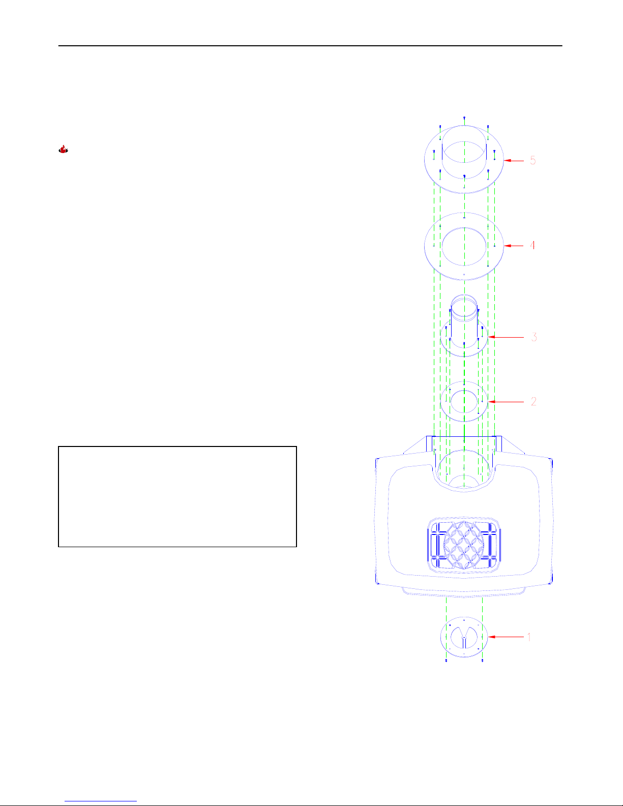
Hearthstone Quality Home Heating Products, Inc. Stowe Model 8321
SAFETY INFORMATION
Your Stowe is very attractive and extremely efficient,
utilizing today’s best technologies. By following a
few simple safety precautions and by performing
minimal maintenance, the unit will remain appealing
while providing years of quality performance.
The installation must conform to local codes or, in
the absences of local codes, the current National
Fuel Gas Code, ANSI Z223.1 (NFPA 54) or
CAN/CGA B149 Installation Code. (Installer
l’appareil selon les codes ou réglements locaux, ou,
en l’absence de tells réglements, selon les Codes
d’installation CAN/CGA B149.)
Do not use this appliance if any gas control part
was under water. Immediately call a qualified
service technician to inspect the heater and to
replace any part of the control system and gas
control that was submerged. (Ne pas se servir de cet
appareil s’il a été plongé dans l’eau, complétement
ou en partie. Appeler un technicien qualifié pour
inspector l’appareil et remplacer toute partie du
systéme de contrôle et toute commande qui ont été
plunges dans l’lau.)
During the first few hours of operation, the appliance
may produce a slight smoke and/or odor. This is
normal during the first several burns. During the
initial burn, open a window(s) to assist in the
removal of the smoke/odor. If the logs appear to
smoke, turn the heater off and call a qualified
service technician.
The appliance and its individual shutoff valve must
be disconnected from the gas supply piping system
during any pressure testing of that supply system at
test pressures in excess of ½ psig. (3.5k Pa).
FIRE HAZARD
Do not store or use gasoline or other flammable
vapors or liquids in the vicinity of this appliance. The
Stowe should be located out of traffic and away from
furniture, draperies, clothing, and flammable
material.
SHOCK HAZARD
When equipped with an optional blower
This appliance is equipped with a three-prong
(grounding) plug for protection against shock
hazard, and must be plugged directly into a properly
grounded three-prong receptacle. Do not cut, or
remove, the grounding prong from the plug.
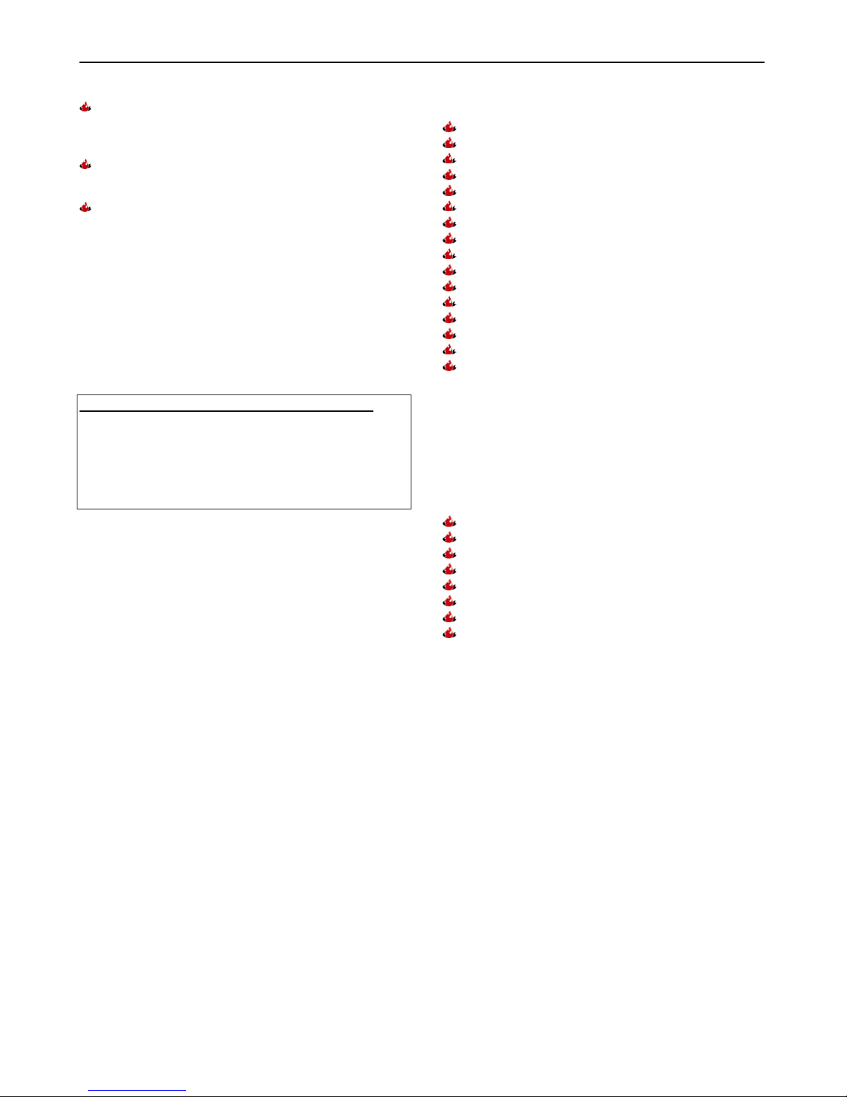
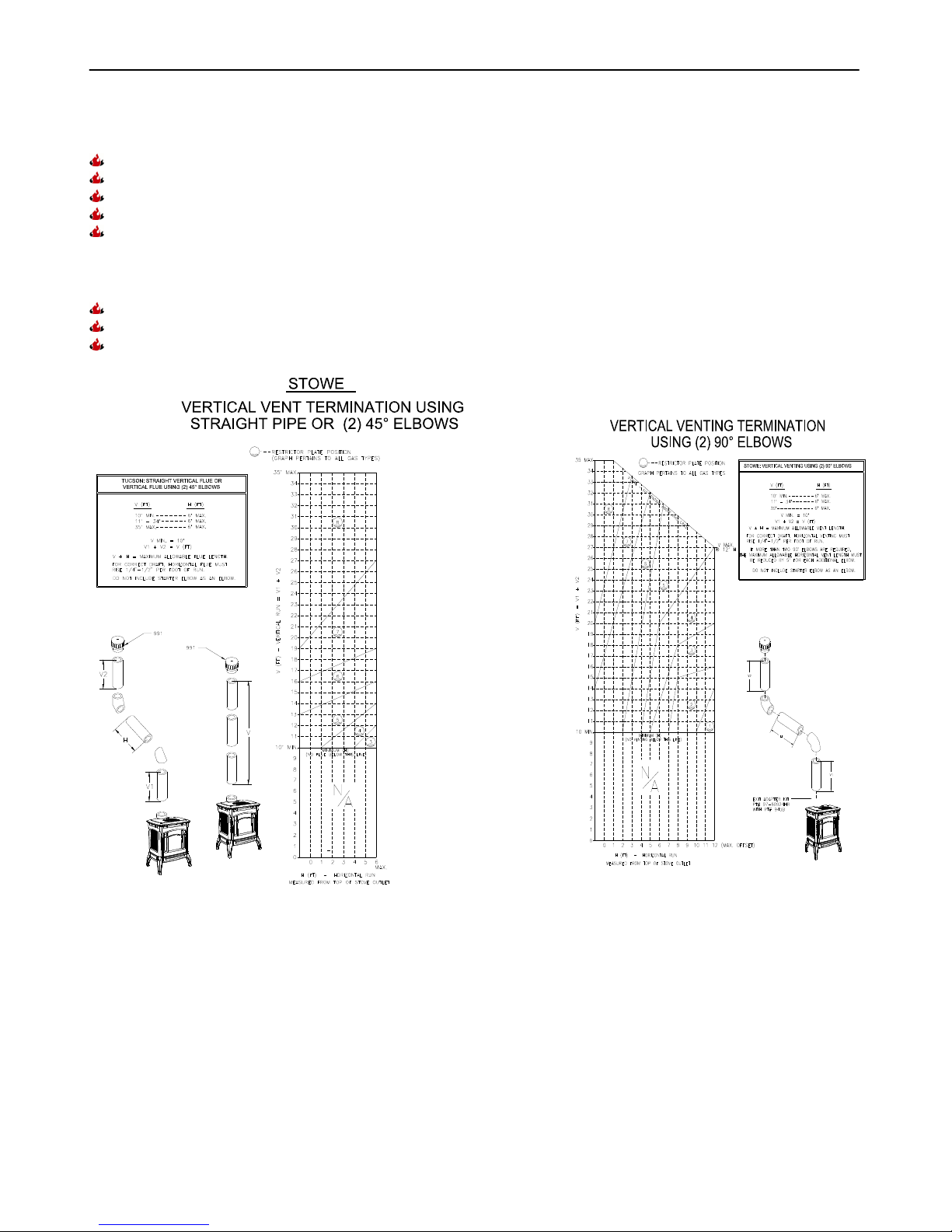
VENT TO THE OUTSIDE
Never vent the gas heater to other rooms, or
buildings – always vent outside. This gas appliance
must not be connected to a chimney flue serving a
separate solid-fuel burning appliance.
SERVICE CAUTION
If you believe your Stowe is not performing properly,
in any way, immediately discontinue operation until
the unit is inspected, and approved for use by
qualified service personnel. Prior to servicing the
unit, turn the valve control knob clockwise to “OFF”.
The unit should be cool prior to servicing and
cleaning. Any safety screen, guard, or component
removed during servicing must be replaced before
operation. Use of any components not supplied by
Hearthstone voids all warranties. Do not substitute
components.
HOT SURFACES
Certain exposed surfaces of the Stowe will reach
high temperatures during normal operation.
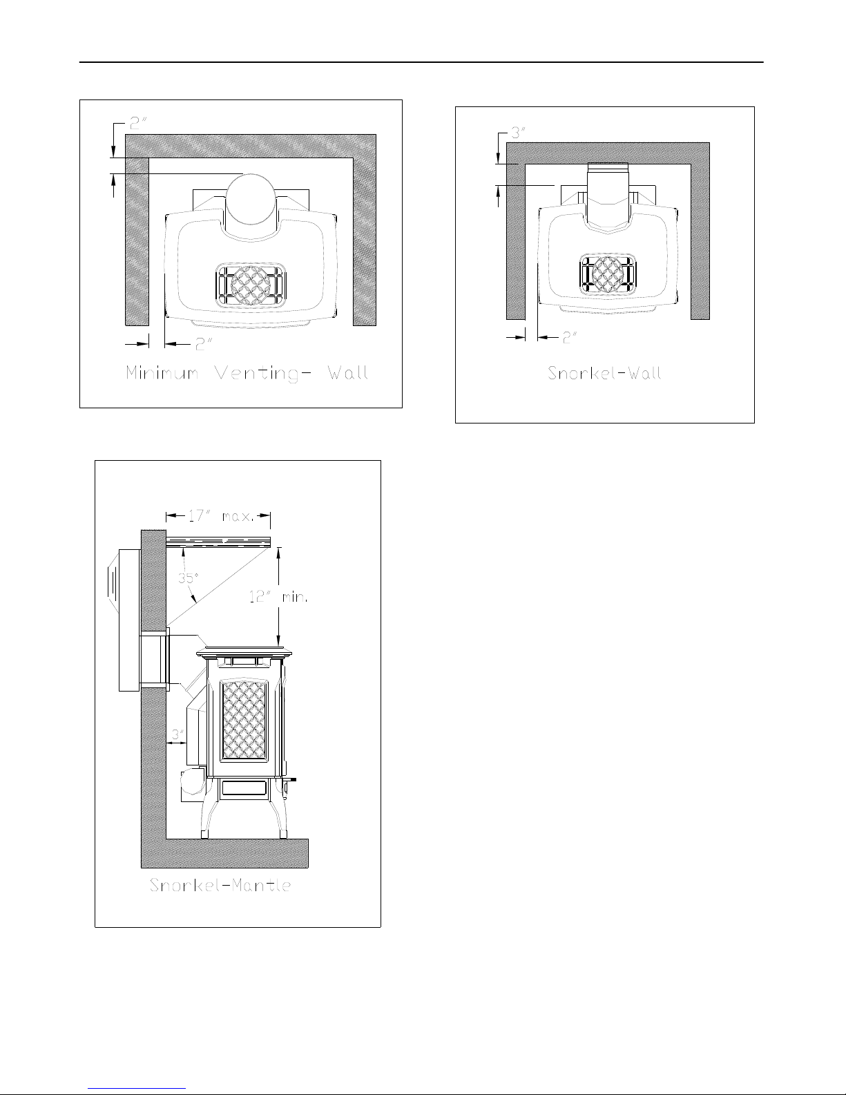
Clearances to combustibles must be maintained, as
specified in the “Clearances To Combustibles”
section of this manual.
Due to high temperatures, the appliance must be
located out of traffic and away from furniture,
draperies, clothing, and flammable materials.
Alert children, and adults, to the hazards of high
surface temperatures, and to stay away to avoid
burns to skin or possible clothing ignition.
Carefully supervise young children when in the
same room as the appliance. Do not place
clothing, or other flammable material, on or near,
the appliance. (Surveille les enfants. Garder les
vêtements, les meubles, l’essence ou autres liquides
à vapeur inflammables lin de l’appareil.)
Clean the area around, under, and behind the unit
on a regular basis to prevent the accumulation of
dust and lint.
NEVER BURN PAPER,WOOD OR OTHER
MATERIALS
This gas heater is designed to burn natural gas, or
liquid propane (LP). Never burn any fuel not
intended for use with this unit.
WARNING! THIS GAS APPLIANCE MUST NOT BE
CONNECTED TO A CHIMNEY FLUE SERVING A
SEPARATE SOLID-FUEL BURNING APPLIANCE
6