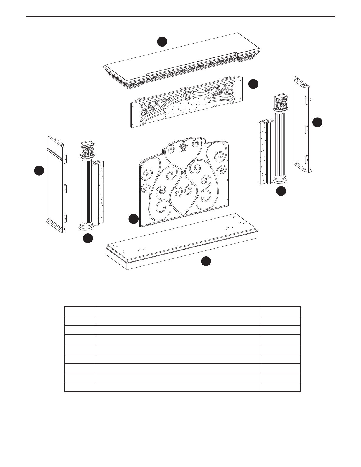
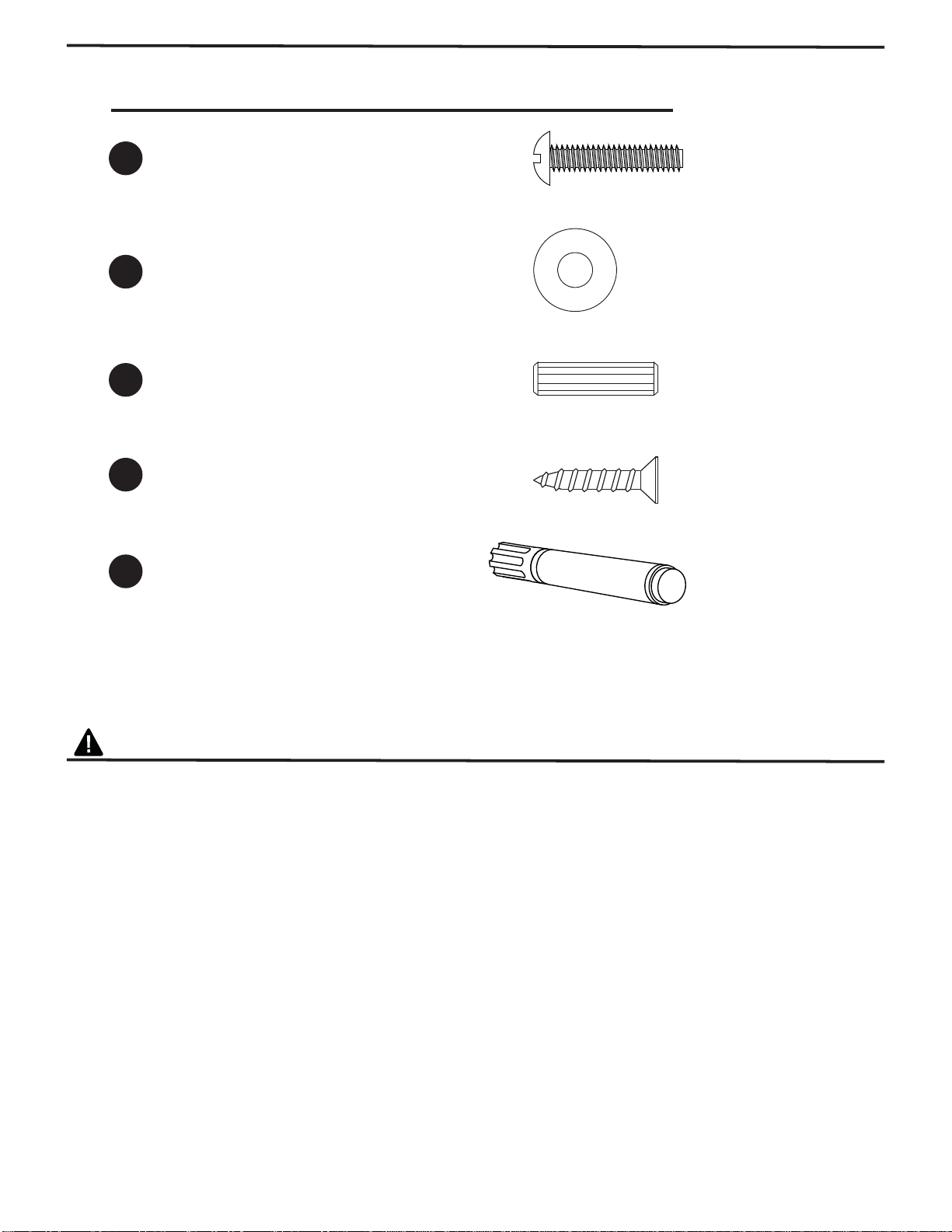
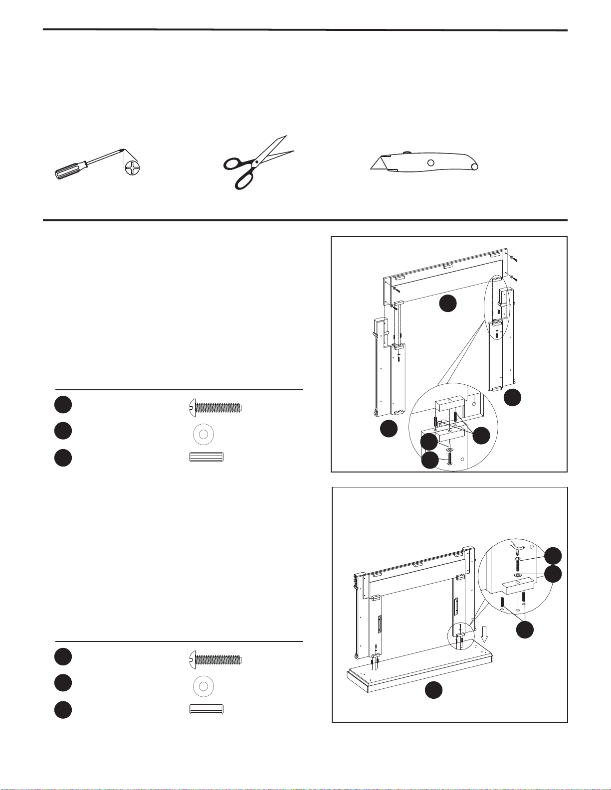
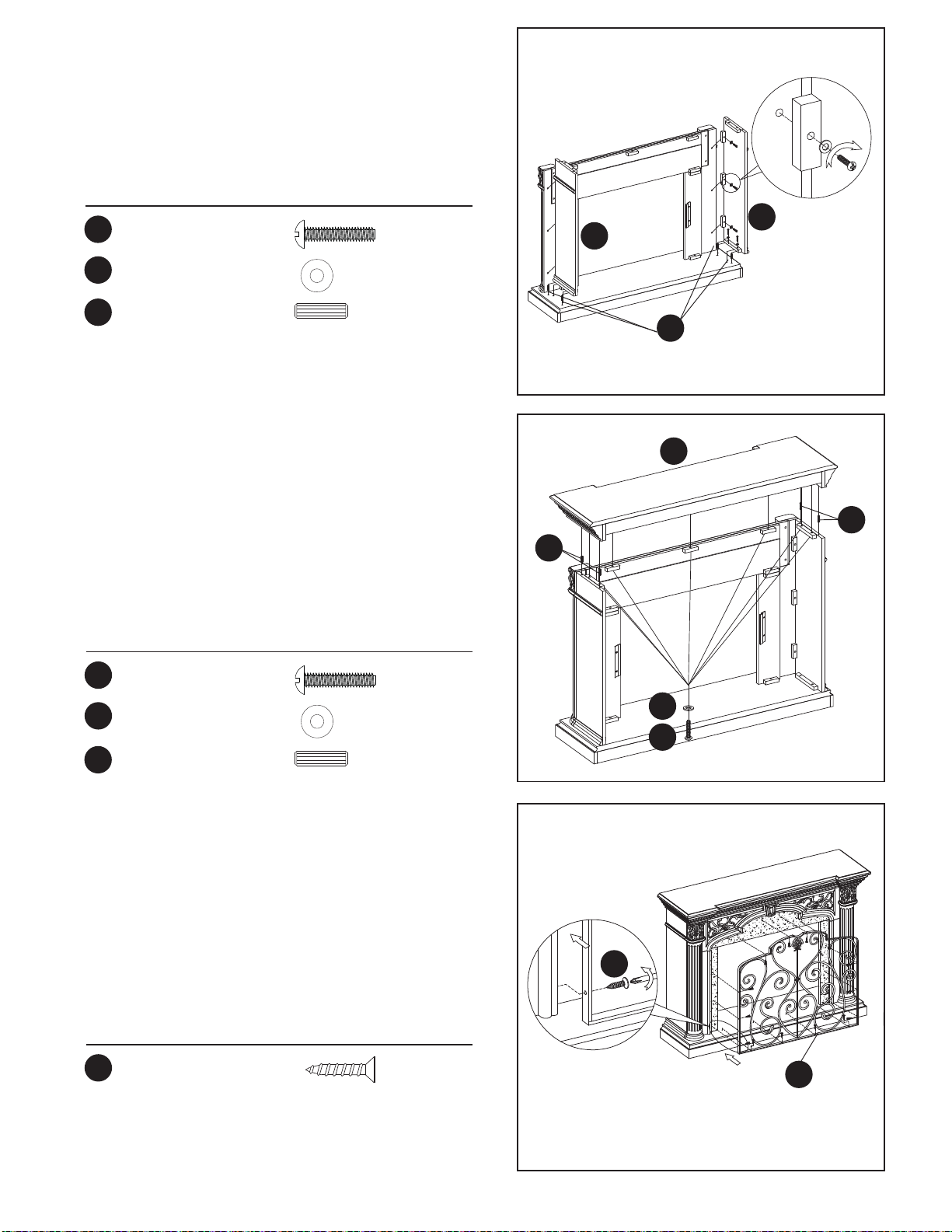
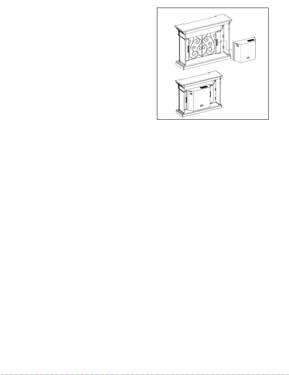
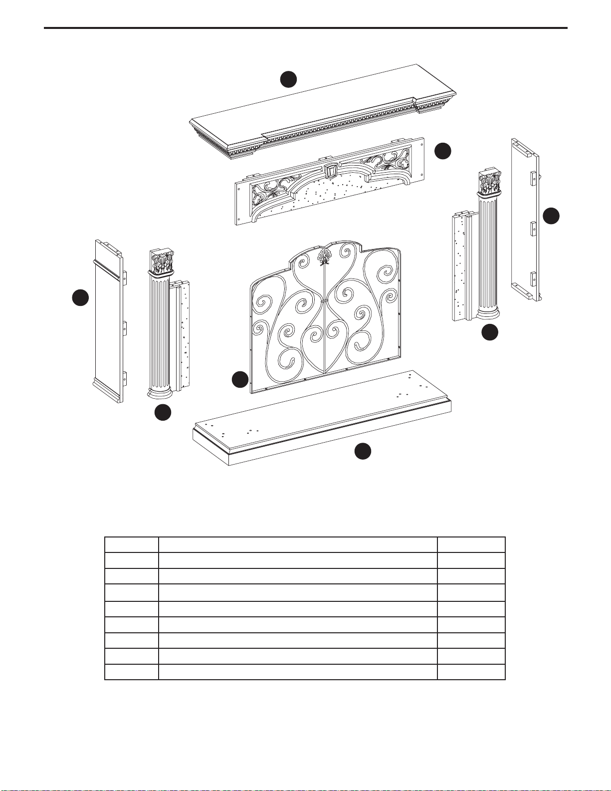
Astoria 33WM0194 User manual

1
ATTENTION
IF YOU HAVE ANY PROBLEMS OR QUESTIONS, EMAIL
OR CALL CUSTOMER SERVICE BEFORE YOU RETURN
THIS PRODUCT TO THE STORE WHERE IT WAS PURCHASED.
For Customer Service: www.twinstarhome.com
in English Call: 866-661-1218
in Spanish Call: 866-661-1218
in French Call: 866-661-1218
ATENCIÓN
SI TIENE ALGÚN PROBLEMA O PREGUNTAS,
ENVÍE UN MENSAJE DE CORREO ELECTRÓNICO O LLAME AL SERVICIO
DE ATENCIÓN AL CLIENTE ANTES DE DEVOLVER
ESTE PRODUCTO A LA TIENDA EN LA QUE LO COMPRÓ.
Servicio de atención al cliente: www.twinstarhome.com
Línea para llamadas en inglés: 866-661-1218
Línea para llamadas en español: 866-661-1218
Línea para llamadas en francés: 866-661-1218
STOP STOP
PARE PARE
ATTENTION
SI VOUS AVEZ DES PROBLÈMES OU QUESTIONS,
ENVOYEZ UN COURRIEL AU SERVICE À LA CLIENTÈLE OU APPELEZ LE
SERVICE À LA CLIENTÈLE AVANT DE RETOURNER
CE PRODUIT OÙ VOUS L’AVEZ ACHETÉ.
Pour le service à la clientèle : www.twinstarhome.com
pour le service en anglais, composez le 866-661-1218
pour le service en espagnol, composez le 866-661-1218
pour le service en français, composez le 866-661-1218
ARRÊT ARRÊT
INSTRUCTION MANUAL ENCLOSED
MANUEL D’INSTRUCTION À L’INTÉRIEUR
MANUAL DE INSTRUCCIONES ADJUNTO
INSTRUCTION MANUAL ENCLOSED
MANUEL D’INSTRUCTION À L’INTÉRIEUR
MANUAL DE INSTRUCCIONES ADJUNTO

1
ELECTRIC FIREPLACE MANTEL
33WM0194
ASSEMBLY INSTRUCTION
Requires-Electric FireplaceRequires-Electric Fireplace
Insert with HeaterInsert with Heater
www.twinstarhome.com
In English call: 866-661-1218
In French call: 866-661-1218
In Spanish call: 866-661-1218
ATTENTION
For Customer Service:
Twin-Star International, Inc.
Delray Beach, FL 33445
Made in China
Printed in China
Españo p. 6
Français p. 11

2
PACKAGE CONTENTS
Part Description Quantity
A Hearth/Base 1
B LH front panel 1
C RH front panel 1
D Center Front Panel 1
E LH end panel 1
F RH end panel 1
G Mantle/Top 1
H Metal grate 1
G
B
A
E
C
F
D
H

3
HARDWARE CONTENTS
Part Description
Bolt
Washer
Wood Dowel
Screw
25+1 extra
25+1 extra
16+1 extra
14+1 extra
Quantity Picture
(Shown to size)
BB
CC
DD
AA
SAFETY INFORMATION
WARNING
• Before assembly, carefully use scissors or utility knife to cut and unwrap all parts.
Make sure you do not discard the hardware.
CAUTION
• Use care in assembling your new fireplace. Take your time and use the hardware
provided and a quality Phillips head screwdriver. Never overtighten bolts.
• Do not sit on any part of the mantel.
• All panels are labeled left and right as viewed from the front of unit.
Touch-up Pen 1
ZZ

4
ASSEMBLY INSTRUCTIONS
PREPARATION
Before beginning assembly of product, make sure all parts are present. Compare parts with
package contents list and diagram above. If any part is missing or damaged, do not attempt to
assemble, install or operate the product. Contact customer service for replacement parts.
Estimated Assembly Time: 60 Minutes
Tools Required for Assembly (not included): Phillips head screwdriver, scissors and utility knife
B
BB CC
C
D
AA
Fig. 1
1. Locate the Center Front Panel (D), RH Front Panel
(C) and LH Front Panel (B) and set out face down
on a scratch-free surface.
Insert one Wood Dowel (CC) into each of the
pre-drilled holes.
Push the RH Front Panel and LH Front Panel
snug to the Center Front Panel. Make sure the
Wood Dowels are seated in the pre-drilled holes.
Insert Bolts (AA) and Washers (BB) into the holes in
the mounting blocks.
HAND TIGHTEN ONLY.
Hardware Used
BB
AA
CC
Bolt x 6
Washer x 6
Wood Dowel x 4
Fig. 2
2. Locate Hearth/Base (A) and set out finished side up
on the floor.
Insert one Wood Dowel (CC) into each of the
pre-drilled holes.
Attach the completed Front panel assembly from
step 1 to the Hearth/Base (A). Make sure the dowels
are seated into the pre-drilled holes in the
Hearth/Base. Using Bolts (AA) and Washers (BB)
attach panels through pre-drilled holes in the
mounting blocks.
HAND TIGHTEN ONLY. CC
AA
A
BB
Hardware Used
BB
AA
CC
Bolt x 2
Washer x 2
Wood Dowel x 4

5
Fig. 3
Hardware Used
BB
AA
CC
CC
Bolt x 10
Washer x 10
Wood Dowel
Wood Dowel
x 4
x 4
E
F
CC
3. Locate LH end Panel (E) and RH end Panel (F),
insert one Wood Dowel (CC) into each of the
pre-drilled holes. Use Bolts (AA) and Washers (BB)
through the pre-drilled holes in the mounting blocks.
HAND TIGHTEN ONLY.
Fig. 4
Hardware Used
BB
AA Bolt x 7
Washer x 7
G
CC
CC
AA
BB
4. Insert one Wood Dowel (CC) into each of the
pre-drilled holes on the top edges of theAssembly
from step 3. Then locate Mantel/Top (G) and lay
finished side up on top of completed assembly.
From the inside, attach Mantel/Top (G) using Bolts
(AA) and Washers (BB) through the pre-drilled holes
in the mounting blocks.
HAND TIGHTEN ONLY.
Using Phillips head screwdriver tighten all Bolts
alternating top and bottom, left and right.
Fig. 5
5. Attach the Metal Grate (H) to the completed Front
panel assembly from step 4. Insert one Screw (DD)
into each of the pre-drilled holes.
Make sure the screws are seated into the pre-drilled
holes in the Metal Grate (H). Tighten all Screws (DD).
DD
H
Hardware Used
DD Screw x 14

6
Fig. 6
Completed
Unit
Electric
Fireplace Insert
Install
Insert
From
Back
6. Remove the two mounting brackets attached to the
back of the Left and Right Front panels. Set aside
with the wood screws.
PLEASE READ ALL “ELECTRIC FIREPLACE
INSERT” INSTRUCTIONS PRIOR TO INSTALLING
ELECTRIC INSERT IN YOUR COMPLETED
FIREPLACE MANTEL. INSTALL THE INSERT IN
YOUR FIREPLACE CLOSE TO ITS FINAL
POSITION.
Lift insert carefully into the back of the unit and
center in the insert opening. Do not drag insert
across Hearth/Base (A) as it may scratch your unit.
Install the mounting brackets to hold insert flush
against the inside of the mantel front panel.
MOVE YOUR COMPLETED UNIT ONLY SHORT
DISTANCES. MOVE COMPLETED UNIT WITH
GREAT CARE. IT TAKES TWO PEOPLE TO MOVE
COMPLETED UNIT INTO ITS FINAL POSITION.

7
CHIMENEA ELÉCTRICA
33WM0194
Necesitará, Además, ElNecesitará, Además, El
Hogar Eléctrico Con CalentadorHogar Eléctrico Con Calentador
www.twinstarhome.com
Línea para llamadas en inglés: 866-661-1218
Línea para llamadas en francés: 866-661-1218
Línea para llamadas en español: 866-661-1218
ATENCIÓN
Servicio de atención al cliente:
Twin-Star International, Inc.
Delray Beach, FL 33445
Fabricado en China
Impreso en China
English. 1
Français p. 11
INSTRUCCIÓN DE MONTAJE

8
Pieza Descripción Cantidad
A Base Del Hogar 1
B LH panel frontal 1
C RH panel frontal 1
D Panel Delantero Central 1
E LH panel final 1
F RH panel final 1
G Repisa/Parte Superior 1
H Rejilla metálica 1
CONTENIDO DEL PAQUETE
G
B
A
E
C
F
D
H

9
Perno
Stylo de retouche
Arandela
Clavija De Madera
Tornillo
25+1 adicional
25+1 adicional
16+1 adicional
14+1 adicional
BB
CC
DD
AA
1
ZZ
INFORMACIÓN DE SEGURIDAD
ADVERTENCIA
• Antes del montaje, corte con unas tijeras o un bisturí y desenvuelva las piezas
cuidadosamente. Asegúrese de no desechar los herrajes.
PRECAUCIÓN
• Tenga cuidado al armar su nueva chimenea. Tómese su tiempo y use los elementos
suministrados y un destornillador Phillips de calidad. No apriete demasiado los pernos.
• No se siente en ninguna parte de la repisa de la chimenea.
• Todos los paneles están etiquetados izquierda y derecha, vistos desde el frente de la unidad.
HERRAJES INCLUIDOS
Parte Descripción Cantidad Imagen
(Tamaño real)

10
PREPARACIÓN
Antes de empezar el montaje del producto, asegúrese de que todas las partes estén
presentes. Compare las piezas con la lista de empaque del paquete y el diagrama de ar-
riba. Si alguna pieza falta o está dañada, no trate de armar, instalar o utilizar el producto.
Llame a servicio al cliente para piezas de repuesto.
Tiempo estimado para el montaje: 60 Minutos
Herramientas necesarias para el armado (no incluidas): Destornillador Phillips, tijeras y
un bisturí.
1. Tome el Panel Delantero Central (D), el RH panel
frontal (C) y el LH panel frontal (B) y colóquelos con
la cara hacia abajo sobre la superficie sin marcas.
Inserte una Espiga De Madera (CC) en cada uno de
los orificios previamente perforados.
Ajuste correctamente el RH panel frontal y el LH
panel frontal al Panel Central.
Compruebe que las Espigas De Madera estén bien
colocadas en los orificios correspondientes. Inserte
un Pernos (AA) y una Arandelas (BB) en los
orificios de los bloques de montaje.
AJUSTE SÓLO MANUALMENTE.
Herrajes utilizados
BB
AA
CC
Perno x 6
Arandela x 6
x 4
Clavija De Madera
INSTRUCCIONES DE MONTAJE
2. Tome la Base Del Hogar (A) y colóquela sobre el
piso con la parte terminada hacia arriba.
Inserte una Espiga De Madera (CC) en cada uno de
los orificios previamente perforados.
Ajuste el conjunto Delantero, que armó en el paso 1,
a la Base Del Hogar (A). Compruebe que las
espigas estén bien colocadas en los orificios
correspondientes de la Base del Hogar. Para ajustar
los paneles, pase un Pernos (AA) y una Arandelas
(BB) por los orificios previamente perforados de los
bloques de montaje.
AJUSTE SÓLO MANUALMENTE.
x 2
x 2
x 4
Herrajes utilizados
BB
AA
CC
Perno
Arandela
Clavija De Madera
B
BB CC
C
D
AA
Fig. 1
Fig. 2
CC
AA
A
BB

11
Fig. 3
E
F
CC
Fig. 4 G
CC
CC
AA
BB
Fig. 5
DD
H
4. Inserte una Espiga De Madera (CC) en cada uno de
los orificios previamente perforados del borde
superior del Conjunto que armó en el paso 3. Luego,
tome la Repisa/Parte Superior (G) y colóquela, con
el lado acabado hacia arrinba, sobre el conjunto
armado. Desde el interior, ajuste la Repisa
colocando un Pernos (AA) y una Arandelas (BB) en
los orificios previamente perforados de los bloques
de montaje.
AJUSTE SÓLO MANUALMENTE.
Utilizando un destornillador Phillips (cruciforme),
apriete todos los pernos, alternando entre la parte
superior e inferior, la izquierda y la derecha.
5. Adjunte la rejilla metálica (H) al montaje del panel
frontal terminado en el paso 4. Inserte un tornillo
(DD) en cada uno de los agujeros pre-agujereados.
Asegúrese de que los tornillos estén bien colocados
en los agujeros pre-agujereados en la rejilla metálica
(H). Apriete todos los tornillos (DD).
x 10
x 7
x 14
x 10
x 7
x 4
x 4
3. Localice el LH panel final (E) y el RH panel final (F)
e inserte una clavija De Madera (CC) en cada uno
de los orificios pretaladrados, que se encuentran
en el reborde inferior de los paneles. Después,
inserte un Pernos (AA) y una Arandelas (BB) a
través de los orificios pretaladra dos de los bloques
para montaje. Fije los el paneles laterales a la Base
(A).
APRIETELOS SOLAMENTE A MANO
Herrajes utilizados
Herrajes utilizados
Herrajes utilizados
BB
BB
AA
AA
DD
CC
CC
Perno
Perno
Tornillo
Arandela
Arandela
Clavija De Madera
Clavija De Madera

12
6. Quite los dos soportes de montaje fijados en la parte
trasera de los paneles Izquierda y derecho. Coloque
a un lado los tornillos para madera.
LEAATENTAMENTE TODAS LAS INSTRUCCIONES
DEL “HOGAR ELÉCTRICO” ANTES DE SU
INSTALACIÓN EN LA CHIMENEA DECORATIVA.
UBIQUE EL HOGAR ELÉCTRICO EN LA
POSICIÓN DEFINITIVA DENTRO DE LA
CHIMENEA.
Levante el hogar cuidadosamente, colóquelo en la
parte posterior de la unidad y céntrelo en la abertura
de la chimenea. No empuje el hogar desde su
Base dado que la unidad se puede dañar. Coloque
los soportes de montaje de modo que el hogar se
encuentre nivelado con respecto a la parte interior
del panel frontal de la repisa.
MUEVA LA UNIDAD COMPLETA SÓLO EN
DISTANCIAS CORTAS. MUEVA LA UNIDAD
COMPLETA CON MUCHO CUIDADO. SE
NECESITAN DOS PERSONAS PARA DESPLAZAR
LA UNIDAD COMPLETAAL LUGAR DEFINITIVO
QUE VAA OCUPAR.
Unidad
Terminada
Hogar
Eléctrico
Instalar
Hogar
Desde
Atrás
Fig. 6

13
MANTEQU DE CHEMINÉE ÉLECTRIQUE
33WM0194
INSTRUCTION DE L'ASSEMBLAGE
English p. 1
Españo p. 8
Nécessite AUSSI un foyer-insertNécessite AUSSI un foyer-insert
électrique avec chauffageélectrique avec chauffage
www.twinstarhome.com
Appel en anglais : 866-661-1218
Appel en français : 866-661-1218
Appel en espagnol : 866-661-1218
ATTENTION
Pour le service à la clientèle :
Twin-Star International, Inc.
Delray Beach, FL 33445
Fabriqué en Chine
Imprimé en Chine

14
CONTENU DU CARTON
Pièce Description Quantité
A Âtre/Base 1
B LH panneau frontal gauche 1
C RH panneau frontal droit 1
D Panneau Avant Central 1
E LH panneau latéral gauche 1
F RH panneau latéral droit 1
G Manteau/dessus 1
H Grille métallique 1
G
B
A
E
C
F
D
H

15
CONTENU DU MATÉRIEL
Boulon
Rondelle
Goujon en bois
Vis
25+1 extra
25+1 extra
16+1 extra
14+1 extra
BB
CC
DD
AA
Crayon pour retouches 1
ZZ
Pièce Description Quantité Illustration
(en taille réelle)
INFORMATION DE SÉCURITÉ
AVERTISSEMENT
• Avant l’assemblage, à l’aide de ciseaux ou d’un couteau universel, coupez et déballez
soigneusement toutes les pièces. Assurez-vous de ne pas jeter de matériel.
MISE EN GARDE
• Faites preuve de prudence dans l’assemblage de votre nouvelle cheminée. Prenez
votre temps et utilisez le matériel fourni et un tournevis cruciforme de qualité. Ne serrez
pas trop les boulons.
• Ne vous asseyez pas sur des pièces du manteau.
• Tous les panneaux sont étiquetés de gauche et de Droit quand on les regarde
en se tenant face à la cheminée.

16
INSTRUCTIONS POUR L’ASSEMBLAGE
PRÉPARATION
Avant de commencer l’assemblage du produit, assurez-vous que toutes les pièces sont présentes.
Comparez les pièces avec la liste du contenu de la boîte et le schéma ci-dessus. Si une pièce est
manquante ou endommagée, n’essayez pas d’assembler, d’installer ou de faire fonctionner le produit.
Communiquez avec le service à la clientèle pour obtenir des pièces de rechange.
Durée d’assemblage estimée : 60 minutes
Outils requis pour l’assemblage (non inclus) : Tournevis cruciforme, ciseaux et couteau universel
1. Trouvez le Panneau Avant Central (D), le RH
panneau frontal droit (C) et le LH panneau frontal
gauche (B) et déposez-les, le côté fini vers le sol,
sur une surface où ils ne pourront être égratignés.
Insérez un Goujon En Bois (CC) dans chacun des
trous pré-percés.
Poussez les panneau frontal de RH et de LH de
chaque côté du panneau central. Assurez-vous
que les goujons en bois soient bien assis dans les
trous pré-percés. Insérez les Boulons (AA) et les
Rondelles (BB) dans les trous des blocs de
montage.
SERRER À LA MAIN SEULEMENT.
Matériel utilisé
BB
AA
CC
Boulon x 6
Rondelle x 6
Goujon en bois x 4
2. Retrouver la base (A) et placer cette pièce sur le
plancher, en dirigeant le côté fini vers le haut.
Insérer un goujon en bois (CC) dans chacun des
orifices préperforés.
Fixer l’assemblage de la façade déjà complétée à
l’étape 1 à la base (A). S’assurer que les goujons en
bois sont installés adéquatement dans les orifices
préperforés de la base. À l’aide d’un boulons (AA)
et d’une rondelles (BB), fixer les panneaux dans les
orifices préperforés des blocs de montage.
SERRER UNIQUEMENT À LAMAIN.
Matériel utilisé
BB
AA
CC
Boulon x 2
Rondelle x 2
Goujon en bois x 4
B
BB CC
C
D
AA
Fig. 1
Fig. 2
CC
AA
A
BB

17
Fig. 3
E
F
CC
Fig. 4 G
CC
CC
AA
BB
Fig. 5
DD
H
3. Retrouver le LH panneau latéral gauche (E) et le
RH panneau latéral droit (F) et insérer un goujon
en bois (CC) dans chacun des orifices préperforés
situés sur les rebords inférieurs des panneaux. Par
la suite, insérer un boulons (AA) et une rondelles
(BB) dans les orifices préperforés des blocs de
montage. Fixer les panneaux latéraux à la base (A).
SERRER UNIQUEMENT À LAMAIN.
4. Insérez un Goujon En Bois (CC) dans chacun des
trous pré-percés de la bordure supérieure du
panneau assemblé à l’étape 3. Trouvez ensuite le
Manteau/Dessus (G). Déposez le côté fini du
manteau sur le dessus du panneau entièrement
monté. De l’intérieur, fixez le manteau à l’aide
d’un Boulons (AA) et d’une Rondelles (BB), en les
insérant dans les trous pré-percés des blocs de
montage.
SERRER À LA MAIN SEULEMENT.
Avec un tournevis cruciforme, serrez tous les
goujons, en alternant entre le haut et le bas, la
gauche et la Droit.
5. Attacher la Grille métallique (H) sur l’assemblage
complété du Panneau frontal de l’étape 4. Insérer
une Vis (DD) dans chacun des trous pré-percés.
Assurez-vous que les Vis soient bien placées dans
les trous pré-percés de la Grille métallique (H).
Serrer toutes les Vis (DD).
Matériel utilisé
Matériel utilisé
Matériel utilisé
x 10
x 7
x 14
x 10
x 7
x 4
x 4
BB
BB
AA
AA
DD
CC
CC
Boulon
Boulon
Vis
Rondelle
Rondelle
Goujon en bois
Goujon en bois

18
6. Retirez les deux brides de montage fixées à
l’arrière des panneaux avant de gauche et de
Droit. Mettez-les de côté, avec les vis à bois.
VEUILLEZ LIRE TOUTES LES INSTRUCTIONS
D’INSTALLATION DU FOYER ÉLECTRIQUE
ENCASTRABLE AVANT D’INSTALLER LE FOYER
DANS LE MANTEAU, UNE FOIS CELUI-CI
ASSEMBLÉ. INSTALLEZ LE FOYER DANS
L’ESPACE PRÉVU, PRÈS DE SA POSITION
FINALE.
Soulevez doucement le foyer encastrable pour le
déposer par l’arrière du manteau, dans le centre de
l’ouverture de celui-ci. Ne pas tirer le foyer
encastrable sur Âtre/Base (A) car cela pourrait
égratigner la base du manteau.
Installez les brides de montage pour ainsi garder le
foyer encastrable à égalité avec l’intérieur du
manteau.
NE DÉPLACEZ LE FOYER ENTIÈREMENT MONTÉ
QUE SUR DE COURTES DISTANCES. DÉPLACEZ
L’UNITÉ MONTÉE AVEC SOIN. IL FAUT DEUX
PERSONNES POUR DÉPLACER L’UNITÉ
MONTÉE ET LA METTRE EN PLACE.
Installer
le foyer
encastrable
par l’arrière
Foyer encastrable
électrique
Unité
assemblée
Fig. 6
Table of contents
Languages:
Popular Indoor Fireplace manuals by other brands

Napoleon
Napoleon Altitude AX36NTE installation manual

Heatilator
Heatilator ST42A owner's manual

Greystone
Greystone F2653BCFW manual

Napoleon
Napoleon GD34-1NT Installation and operating instructions

e-Flame USA
e-Flame USA EF-FS1511 owner's manual

Majestic fireplaces
Majestic fireplaces UVDC Homeowner's installation and operating manual

Flavel
Flavel Calypso FNCN**SN Series User instructions

Sunjoy
Sunjoy Sunnest A304001006 manual

Regency Fireplace Products
Regency Fireplace Products CI1200 Alterra Owners & installation manual

FMI
FMI CGEF23B Safety information and installation manual

kozy heat
kozy heat Dassel DSL-36-RF Installation and operation manual

Masport
Masport Inverell installation instructions