4
ELECTRIC AND COMBINATION STOVES ONLY
STOVE
TOP
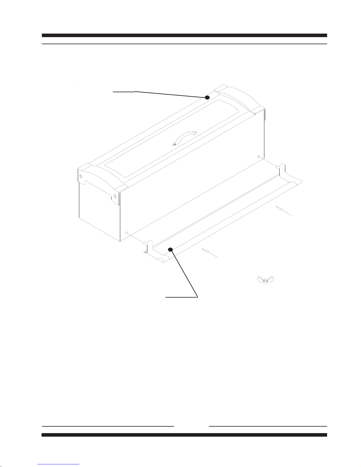
Gasket - Peel off backing
and stick on.
Bracket
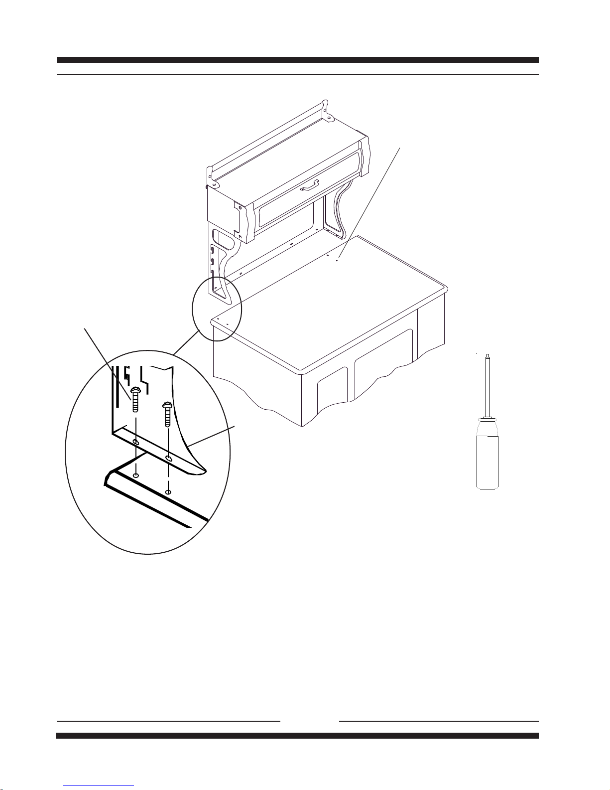
Sheet metaI
screw (black)
Steel Washer Machine screw
(NickelPlated)
-Remember when working with the cabinet, the cabinet is top heavy. Use your hand to support it during
installation.
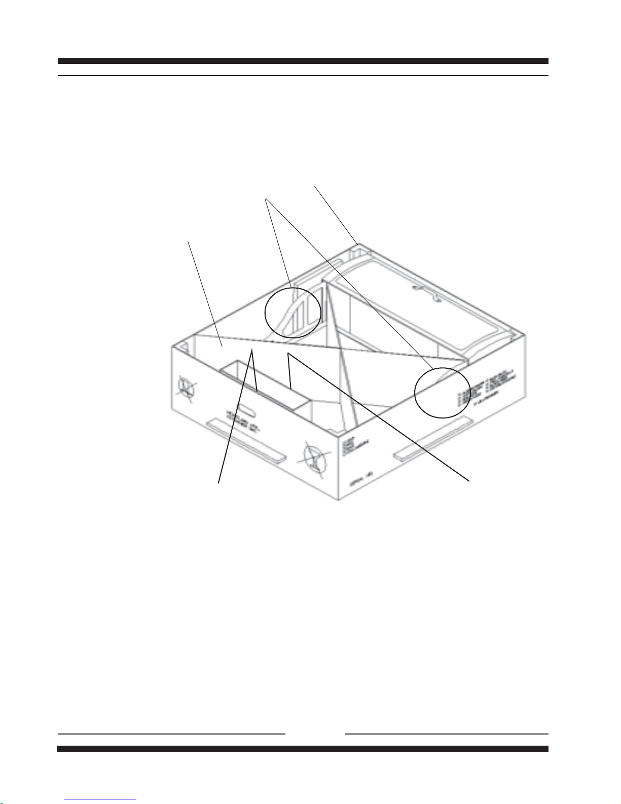
-Place box on the floor close to stove. (See Fig. 1 Page 2).
-With a helper,lift cabinet assembly from box by area that is circled.(See Fig.1 Page 2).
-Rest the cabinet assembly on the carton,while your helper steadies the cabinet,peel the cabinet backing off the
gasket and stick one on each bracket.
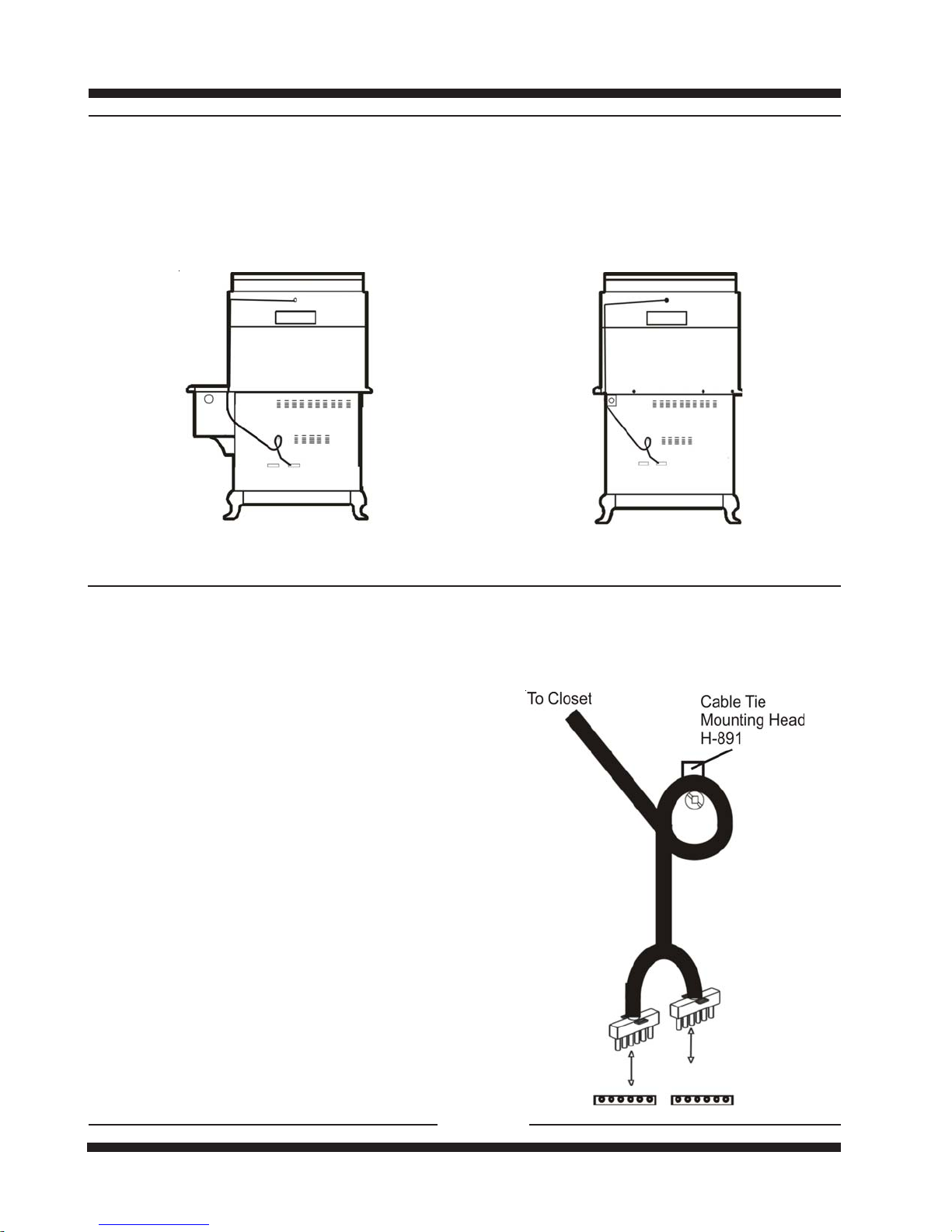
-Placecabinetassemblyontostovebody.(Seediagramabove)
Caution: In the case of the Glass cooktop models 8200, 8210, 6200, 6210:
DONOT REST CLOSET CORNER BRACKETS ON GLASS, to prevent damage to glass top
-Line up holes in the bottom (foot) of the bracket with the holes in the stove top,while one person supports the
cabinet, fasten the cabinet brackets to the stove top with machine screws .
-To fasten the splashback to the rear of stove, with the Models 5200, 5210, 6200, 6210 use 5 sheet metal
screws and washers. For Models 4200, 4210, 8200, 8210 use 4 sheet metal screws and washers. To prevent
chipping do not overtighten or use power tools.
Gasket
Machine screw
Steel washer
Sheet metal
screw