Heat & Glo GFK-160T User manual

Heat & Glo Lifestyle Collection • GFK-160T Instructions • 2087-023 Rev. E • 6/10 1
FIGURE 1
GFK-160T Blower System
- Installation and Operating Instructions -
Note: For ease of installation install Fan Kit prior to
gas line installation.
1.0 INTRODUCTION
The GFK-160T Blower has been designed to circulate
roomairthroughthefireplacetoenhanceheatoutput.The
GFK-160T blower system operates on 120 VAC, 60 Hz
power. This is available through a receptacle in the factory
installed junction box. The junction box is located in the
controls compartment of the fireplace.
Avariablespeedcontrolisprovidedwiththe blower system
to provide quiet forced air flow at the desired speeds. A
temperature sensor switch, which automatically turns the
blower ON/OFF, is also provided with this kit.
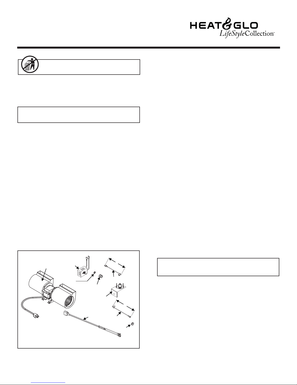
2.0 CHECK CONTENTS OF SHIPPING CARTON
Compare CONTENTS OF CARTON in Figure 1 with the
actualpartsreceived. If any parts are missing ordamaged,
contactyour dealerbefore startinginstallation.Do notinstall
a damaged blower kit.
3.0 INSTALLATION PRECAUTIONS
TheGFK-160TBlowerKitistestedandsafewheninstalledin
accordancewith this installationmanual.It is yourresponsi-
bilitytoreadall instructionsbefore startinginstallation andto
followtheseinstructionscarefullyduringinstallationtoassure
maximum benefit from, and safe operation of, the blower.
This blower is carefully engineered and must be installed
only as specified. If you modify it or any of its components,
youmaycause a fire hazard and will voidtheWARRANTY.
In addition, such action may void the coverage provided
by the owner's home insurance.
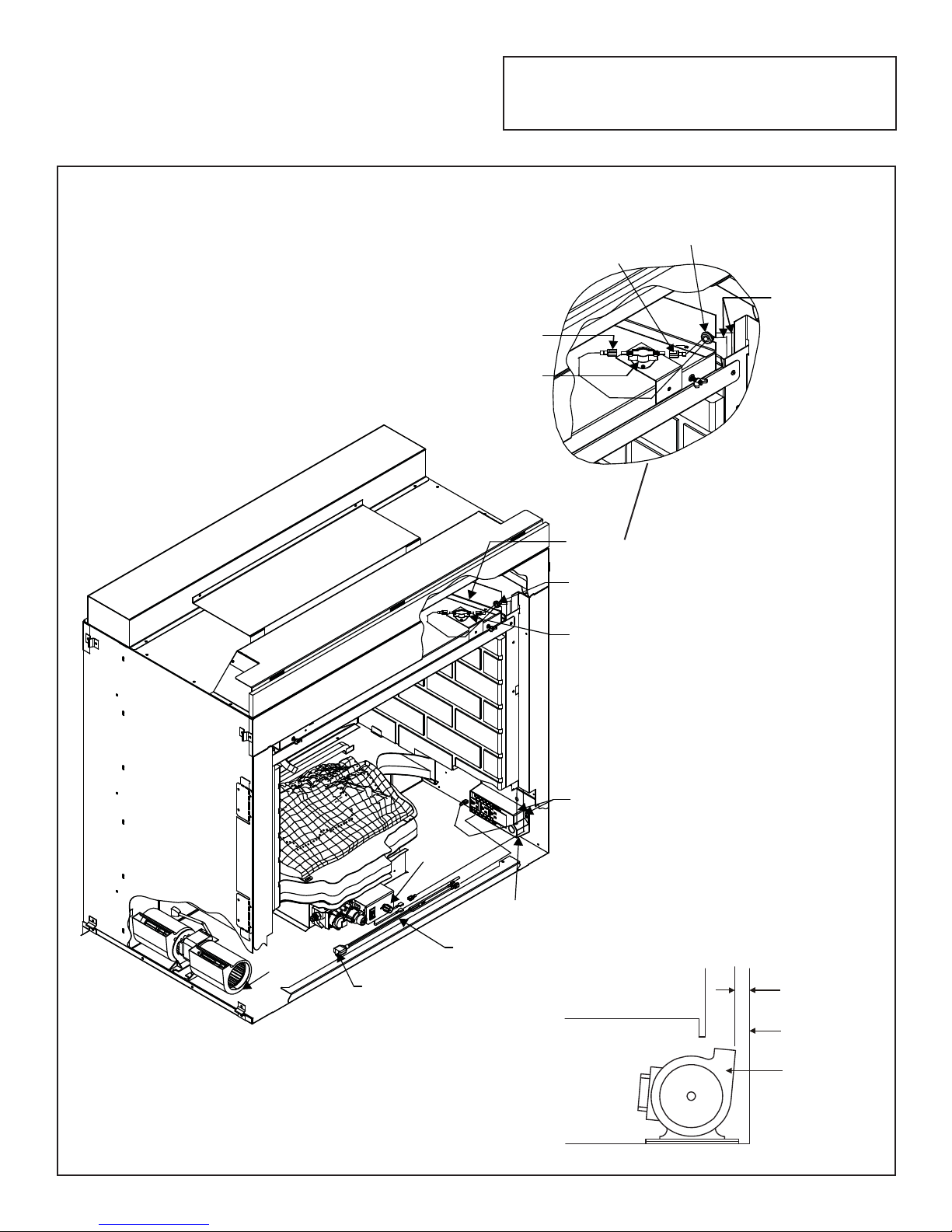
2. Feed the 110-120 VAC electrical service wires
through the Romex clamp and secure the wires to
the clamp.
3. Access the controls compartment of the fireplace to
locate the Junction Box.
4. Using the wire nuts, attach the black wire to the black
service wire, the white wire to the white service wire, and
the service ground wire to the ground stud of the junction
box.
5. Attach the junction box to the side of the unit. Insert the
rear tab of the box into the rectangular slot in the outer
wrap of the firebox. Push the front end of the box tightly
against the side of the unit, and secure the box with a
sheet metal screw (note the hole in the front end tab).
4.0 INSTALLATION INSTRUCTIONS
4.1 INSTALLING ELECTRICAL SERVICE
TO THE JUNCTION BOX
CAUTION: All wiring should be done by a qualified electrician
and shall be in compliance with local codes and with the National
ElectricCodeANSI/NFPANO.70-current(intheUnitedStates),or
with the current CSAC22.1 Canadian Electric Code (in Canada).
Leave this manual with party responsible for use
and operation.
CAUTION! Risk of Cuts or Abrasions. Wear protective
gloves and safety glasses during installation. Sheet metal
edges are sharp.
WARNING! Risk of Shock or Explosion! DO NOT wire
110V to the valve or to the appliance wall switch.
• Incorrect wiring will damage this valve.
• Incorrect wiring will override IPI safety lockout.
WARNING! Risk of Shock! Turn electrical power off at
the circuit breaker before beginning this installation.
NOTE: This fireplace model has a round hole through which
the service wires are fed and into which the Romex
clamp is attached.
1. Attach a Romex clamp (not included with unit) with
screws to the outside.
CORD
BLOWER
TEMPERATURE
SENSOR
SWITCH
SPEED
CONTROL
CONTROL
NUT CONTROL
KNOB
WIRE
LEAD
6’
WIRE
LEAD
GROMMET
6’

Heat & Glo Lifestyle Collection • GFK-160T Instructions • 2087-023 Rev. E • 6/10
2
FIGURE 2
4.2 INSTALLING THE BLOWER
Positionthe blowerall thewayto theleftsideofthe fireplace
and center front to back. Pull the blower 1/8" to 1/4" away
from the side wall of the fireplace, see Figure 2.
DETAIL A
Note: For wiring information see Figure 4. Position
the temperature switch as shown in Detail A, Figure
2. Secure in place with a screw supplied with this kit.
FIREPLACE
WALL
BLOWER
1/8” TO 1/4”
GROMMET
TEMPERATURE
SENSOR SWITCH
DETAIL A
WIRE LEADS THROUGH
SIDE OF UNIT
JUNCTION
BOX
CORD
ASSEMBLY
SPEED
CONTROL
PLUG BLOWER
NTO CORD ASSEMBLY
BLOWER
LEADS DOWN SIDE
OF FIREPLACE
GROMMET
LEAD TO
SPEED CONTROL
LEAD TO
JUNCTION BOX
TEMPERATURE
SENSOR SWITCH

Heat & Glo Lifestyle Collection • GFK-160T Instructions • 2087-023 Rev. E • 6/10 3
4.3 INSTALLING THE SPEED CONTROL
AND SENSOR SWITCH
1. Remove the knob and locknut from the variable speed
control. Slide the control behind valve bracket in the
front of fireplace, with the stem sticking out of the pre-
punched hole. Attach the locknut tightly and reattach
the knob on the stem.
2. Secure wires to sensor switch bracket.
3. Slide the temperature sensor switch/bracket assembly
ontothe fireboxinner topoffireplace.Securethe bracket
assembly with supplied screw, see Figure 3.
NOTE: Theswitch/bracketassembly must be installed
so that the sensor switch is towards the top of the unit.
4. Connectthevariable speed control and thetemperature
sensorswitch tothejunction boxwiththe wiresprovided.
For the wiring diagram see Figure 4.
5. Turnthe110-120 VACservice"ON" at thecircuitbreaker
and turn the speed control switch to the "ON" position.
FIGURE 4 Fan Wiring Diagram
NOTE: IF ANY OF THE ORIGINAL WIRE AS SUPPLIED WITH THE APPLIANCE
MUST BE REPLACED, ITMUST BE REPLACED WITHTYPE 105O C RATED WIRE.
SPEED
CONTROL
BLOWER
JUNCTION BOX
TEMPERATURE
SENSOR
SWITCH
WIRE LEAD
WIRE LEAD
CORD ASSEMBLY
GROMMET
GLASS
RETAINER
WING NUT (2)
HOOD
SCREW
TEMPERATURE
SENSOR SWITCH
FIGURE 3

Heat & Glo Lifestyle Collection • GFK-160T Instructions • 2087-023 Rev. E • 6/10
Please contact your Hearth & Home Technologies
dealer with any questions or concerns.
For the location of your nearest
Hearth & Home Technologies dealer,
please visit www.fireside.com.
4
5.0 RECOMMENDED OPERATING
PROCEDURES
Ignitethe fireinthe fireplacewiththe variable speedcontrol
switch in an "ON" position. The fan will automatically turn
on when the temperature sensor switch closes at approxi-
mately 110OF. Heated air should be delivered at the outlet
grille. The fan will continue to operate after the fireplace is
turned OFF until the sensor switch opens.
Various conditions such as type of fireplace installation
and outside air temperature vs. inside air temperature can
contribute to the length of the time the blower remains on
afterthefireplaceis turned OFF.The blower can be turned
off manually with the speed control switch.
6.0 MAINTENANCE
Periodically check the fireplace grilles and remove any
dust, dirt or obstructions.
7.0 REPLACEMENT PARTS AND CUSTOMER
SERVICE
Replacement parts and service may be obtained through
your dealer.
WARNING! Risk of Injury! DO NOT contact blower
wheel (fan blades) during operation.
DESCRIPTION SERVICE PART NUMBER
Wire Plug Assembly 2087-026
Temp Sensor Assembly 2087-022
72 Inch Wire Assembly 258-501A
80 Inch Wire Assembly 522-501A
Blower 107-500A
Table of contents