Oxygen X-Air V200E User manual

Rev 1.1 2021.04
INSTALLATION AND OPERATION MANUAL
Heat Recovery Unit OXYGEN X-Air V200E
enthalpy exchanger

1

2
TABLE OF CONTENTS
1. TRANSPORTATION AND STORAGE OF EQUIPEMENT................................................................................................. 3
2. UNIT PACKAGE ........................................................................................................................................................... 4
3. SAFETY REQUIREMENTS............................................................................................................................................. 5
4. EU DECLARATION OF CONFORMITY........................................................................................................................... 6
5. TECHNICAL DATA ....................................................................................................................................................... 7
5.1. Product information sheet. Delegated Regulation (EU) 1254/2014............................................................. 7
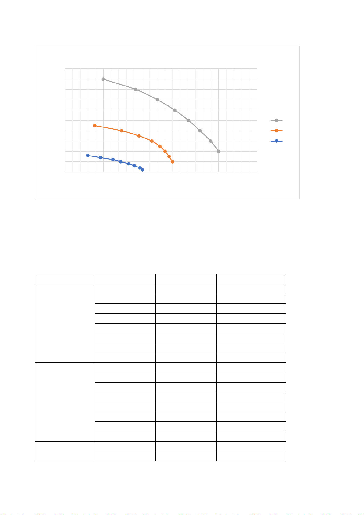
5.2. Performance curves ...................................................................................................................................... 8
5.3. Performance and power consumption ......................................................................................................... 8
5.4. Sound characteristics.................................................................................................................................. 10
9.2. Dimensions and weight............................................................................................................................... 11
6. FUNCTIONALITY ....................................................................................................................................................... 12
7. INSTALLATION OF THE UNIT .................................................................................................................................... 13
7.1. Selecting the mounting location................................................................................................................. 13
7.2. Connecting ducts ........................................................................................................................................ 13
7.3. Maintenance space..................................................................................................................................... 14
7.4. Ventilation system balancing...................................................................................................................... 15
8. CONNECTION OF THE UNIT...................................................................................................................................... 16
8.1. Connecting electric circuit .......................................................................................................................... 17
8.2. Installation of the control panel ................................................................................................................. 17
8.3. Connector of comfort functions ................................................................................................................. 18
8.4. Control board electrical wiring diagram ..................................................................................................... 20
8.5. Description of control board contacts ........................................................................................................ 21
9. OPERATION OF THE UNIT......................................................................................................................................... 22
9.1. WiFi controller ............................................................................................................................................ 22
9.1.1. Downloading the app ............................................................................................................................. 22
9.1.2. WiFi connection set-up........................................................................................................................... 23
9.1.3. App home screen.................................................................................................................................... 25
9.1.4. Setting up weekly operation program.................................................................................................... 25
9.1.5. Ventilation boost activation ................................................................................................................... 26
9.1.6. Away....................................................................................................................................................... 26
9.1.7. Filter menu ............................................................................................................................................. 27
9.1.8. Resetting WiFi controller to factory defaults ......................................................................................... 27
9.2. Control panel with touchscreen display ..................................................................................................... 28
9.2.1. Standby mode......................................................................................................................................... 28
9.2.2. Main screen............................................................................................................................................ 29
9.2.3. Settings menu......................................................................................................................................... 30
9.2.4. Setting up weekly operation program.................................................................................................... 31
9.2.5. Failure indication .................................................................................................................................... 31
9.3. Control panel with a knob........................................................................................................................... 32
9.3.1. Operating state indicator ....................................................................................................................... 32
9.3.2. Air filter replacing / anti-frost protection indicator ............................................................................... 33
9.3.3. Failure indicator...................................................................................................................................... 33
9.3.4. RESET procedure .................................................................................................................................... 34
9.3.5. Resetting the filter lifetime meter.......................................................................................................... 34
9.3.6. Additional system settings ..................................................................................................................... 35
9.4. Replacing air filters ..................................................................................................................................... 36
10. MAINTEINANCE AND WARRANTY............................................................................................................................ 38
11. CONTACTS................................................................................................................................................................ 39

3
1. TRANSPORTATION AND STORAGE OF EQUIPEMENT
Heat Recovery Unit (hereinafter –the Unit) is prepared for transportation and storage. Packaging
materials ensure protection against exposure to environment, dust and humidity. The Unit must be
properly secured during transportation to protect it against possible housing deformation or other
mechanical damage.
Transportation conditions:
-20oC - +40oC.
Long-term storage conditions:
+5oC - +40oC, relative air humidity <= 50%.
CONSIGNMENT ACCEPTANCE:
•Carefully check the received consignment –make sure that the number of packages matches
with the consignment documentation. Upon noticing any non-conformity or damage of the
package (tears, dents or compressed box, detached or reattached packaging tape), inform the
courier immediately and indicate the disrepancies or damages in the consignment document.
•Verify if the right product was delivered. Upon noticing any non-conformity, inform the Sender
immediately.
•Verify if all the supplementary parts listed were delivered. In case of any doubt, contact the
Sender immediately.
•Do not attempt to repair the Unit, damaged during the transportation by yourself!
IMPORTANT! Sender does not assume any obligations towards damage or loss of the Unit or its part,
if there is no a corresponding record in the consignment document!

4
2. UNIT PACKAGE
Heat Recovery Unit OXYGEN X-Air V200E
1 pc
Control panel (10m connection cable included) or WiFi adapter
1 pc
Fastening elements:
Mounting bracket
1 pc
Installation manual
1 pc

5
3. SAFETY REQUIREMENTS
Carefully read and follow safety requirements provided below before installing and while operating
the Unit:
•Do not discard the Installation and operation manual, keep it for future reference.
•The Unit should be installed and operated in compliance with this Installation and operation
manual, following the requirements of effective legislation and standards.
•When connecting the Unit to mains supply, grounding must be installed in compliance with
requirements of effective legislation and standards.
•To prevent accidents and potential damage to the Unit it should be installed, connected,
maintained and repaired only by qualified technician. Never attempt to do this by yourself!
•Turn off the Unit by using Control panel and wait for fans to stop completely before replacing
air filters.
•Turn off the Unit by using Control panel, wait for fans to stop completely and disconnect the
Unit from mains supply before performing any maintenance.
•Disconnect the Unit from mains supply before disconnecting or reconnecting the control
panel.
•Before connecting the Unit make sure that no items will get sucked into the its air intake
openings!
•The Unit is not intended to be used by persons (including children) with reduced physical,
sensory or mental capabilities, unless they have been instructed to use the Unit and under
constant supervision of person held responsible for their safety.
•Children may only use the Unit under adult supervision.
•Only original supplementary parts and consumables, certified by manufacturer should be
used.
•The Unit package (cardboard, plastic, foam polystyrene) can pose hazard to children. Dispose
or recycle the package elements!
•Disused Unit should be disposed in accordance with requirements of legislation on handling
of waste electrical and electronic equipment.
•IT IS PROHIBITED to operate the Unit with damaged mains supply cable! Switch off the power
circuit-breaker to disconnect mains supply and contact a qualified technician or manufacturer
service centre immediately upon noticing such damage.
•IT IS PROHIBITED to attempt the repair of the damaged Unit or its part, to open its cover!
Contact a qualified technician or manufacturer service centre.
•IT IS PROHIBITED to operate the Unit while construction works are still in progress to remove
dust or excess moisture. Fine dust of building materials, used in construction, can irreversibly
change characteristics of the heat exchanger or cause damage to sensitive electronic
components. Failure of the Unit caused by such operation will void the warranty.

6
4. EU DECLARATION OF CONFORMITY
We, undersigned below, representing the manufacturer of ventilation equipment:
Sviezias oras, JSC
Birzelio 23-osios g. 23G
50220 Kaunas
LITHUANIA
confirm, that heat recovery ventilation device OXYGEN X-Air V200E conforms to Europe Union
standarts, directives and regulations:
2009/125/EC –eco-design requirements for energy-related products
ES 1253/2014
ES 1254/2014
ES 2017/1369
EN 13141-7:2010
2010/30/EU –labelling and standard product information of the consumption of energy and other
resources by energy-related products
ES 1254/2014
2011/65/EU –restriction of the use of certain hazardous substances in electrical and electronic
equipment (RoHS)
EN 50581(2012)
2014/35/EU –harmonization of the laws of the Member States relating to the making available on
the market of electrical equipment designed for use within certain voltage limits
EN 60335-1:2012
EN 60335-1:2012/A11:2014
CEO Zilvinas Salialionis
01.02.2021, Kaunas

7
5. TECHNICAL DATA
5.1. Product information sheet. Delegated Regulation (EU) 1254/2014
a)
Supplier's name or trade mark
OXYGEN
b)
Model identifier
X-Air V200E
c)
Specific energy consumption (SEC), SEC
class
A
Cold climate
kWh/m2.a
-85.4
Average climate
kWh/m2.a
-41.3
Warm climate
kWh/m2.a
-16.0
d)
Declared typology
Bi-directional,
residential ventilation
e)
Type of drive installed or intended to be
installed
Multi-speed drive
f)
Type of heat recovery system
Recuperative
g)
Thermal efficiency of heat recovery
%
86.2
h)
Maximum flow rate
192
i)
Electric power input of the fan drive,
including any motor control equipment, at
maximum flow rate
W
165
j)
Sound power level (LWA)
51
k)
Reference flow rate
m3/s
0.040
l)
Reference pressure difference
Pa
50
m)
Specific power input (SPI)
W/(m3/h)
0.37
n)
Control factor
0.65
Control typology
Local demand control
o)
Declared maximum leakage rate:
internal
%
1.6
external
%
1.7
q)
Position and description of visual filter
warning
Refer to installation
and operation manual
s)
Internet address for pre-/dis-assembly
instructions
www.oxygenvent.com
v)
The annual electricity consumption (AEC)
kWh/100m2.a
240
w)
The annual heating saved (AHS)
Cold climate
kWh/100m2.a
9028
Average climate
kWh/100m2.a
4615
Warm climate
kWh/100m2.a
2087

8
5.2. Performance curves
Graph. 1. Ventilation power dependence on the resistance of installed ventilation system
5.3. Performance and power consumption
Power setting
Resistance, Pa
Air flow, m3/h
El. consumption, W
100%
100
196
155
150
190
150
200
176
146
250
161
144
300
143
142
350
120
139
400
92
136
450
50
128
70%
50
140
54
75
136
54
100
130
53
125
123
51
150
113
50
175
96
49
200
74
47
225
39
47
50%
20
101
25
30
98
25
0
50
100
150
200
250
300
350
400
450
500
050 100 150 200 250
Pasipriešinimas, Pa
Oro srautas, m3/h
Galios kreivės
Max
Vid
Min

9
40
90
24
50
83
24
60
73
24
70
62
23
80
46
23
90
30
22
Measured with M5 class filters installed.

10
5.4. Sound characteristics
Power
setting
Air duct
Sound power level (LWA)
Octave band, Hz
Total
125
250
500
1000
2000
4000
8000
50%
Suppply
Extract
Outside
Exhaust
70%
Suppply
Extract
Outside
Exhaust
100%
Suppply
Extract
Outside
Exhaust
Measured according to LST EN13141-7.

11
9.2. Dimensions and weight
Figure 1. Unit dimensions
Body dimensions and weight
Width, mm
Height, mm
Depth, mm
Weight, kg
OXYGEN X-Air V200E
599
690
341
27
OXYGEN X-Air V200E left-side version
A –outside air
B –exhaust air
C –supply air
D –extract air
A –extract air
B –supply air
C –exhaust air
D –outside air
OXYGEN X-Air V200E right-side version

12
6. FUNCTIONALITY
Function
Control panel
with a rotary
switch
LCD control
panel / WiFi
controller
Ventilation
Efficient EC fans
✓
Stepless ventilation intensity adjustment within 30-100% range
✓
✓
Ventilation intensity setting at 5% steps within 30-100% range
Weekly operation program, up to 4 different modes for every week day
Ventilation boost activation by control panel button
System balancing by adjusting power of each fan
✓
Display of indoor air temperature and relative air humidity
Display of date and time
Stepless increase of preheater power
✓
Ventilation boost activation by external switch
✓
"Away" - reduced ventilation power, when the security system is active
✓
Adjustment of ventilation power according to CO2 level indoors
✓*
Adjustment of ventilation power according to humidity level indoors
✓*
Disabling of supply or exhaust air stream
Filtration
G4 (EN 779:2012) / COARSE 65% (ISO 16890), exhaust air filtering only
✓
G4 Carbon (EN 779:2012) / EPM2.5 60% (ISO 16890), retains average size
particles and unwanted odors
✓
M5 (EN 779:2012) / EPM10 50% (ISO 16890), retains average size particles
✓
F7 (EN 779:2012) / EPM1 70% (ISO 16890), retains smallest particles and
pollen
✓
Visual warning of the necessity to replace filters
✓
Filter lifetime metering
✓
Protection functions
Overheat protection
✓
Anti-frost protection
✓
Ventilation shutdown function upon activation of fire alarm
✓*
Visual warning of the Unit failure
✓
Additional functions / features
Possibility to install according to the layout of outdoor ventilation openings
(right-side / left-side versions)
✓**
Control of electric damper
✓**
Control of in-duct comfort heater
✓**
* requires additional ventilation system components to be purchased
** depends on device configuration, to be selected prior ordering the Unit and software version

13
7. INSTALLATION OF THE UNIT
7.1. Selecting the mounting location
The Unit should be installed in a heated room such as storage room, boiler room, garage or an attic.
Make sure, that there is sufficient space to install not only the Unit itself, but also auxiliary ventilation
system components –electrical heater, noise silencers or air distribution boxes.
Operating conditions:
+15oC - +24oC, relative air humidity <= 50%.
The Unit should be installed vertically. Mounting bracket (provided) should be used to fasten Unit to
the wall. Use wall pins or locking sleeves (not included), depending on installation surface. Use vibro-
isolation gaskets (not included) if necessary.
7.2. Connecting ducts
It is recommended to connect the indoor and outdoor air intake and exhaust ducts to the Unit by
using couplings with rubber gaskets. It is necessary to seal the connection place well if any other type
of connections is used.
Figure 2. Air intake duct connection diagram

14
Make sure that outdoor humidity or precipitation will not get into the Unit, when connecting outside
air supply and exhaust ducts. The air intake opening in the outside wall should be protected against
precipitation ingress to ventilation duct by grille or roof.
It is recommended to install outside air supply and exhaust ducts as far as possible from each other
to prevent the ingress of contaminated air back to premises. Please refer to local construction
regulations.
IMPORTANT! Seal the air intake and exhaust ducts connection place well. Use couplings with rubber
gaskets or other selected sealant.
IMPORTANT! At least 1° ventilation duct incline (refer to Figure 2. Air intake duct connection
diagram") should be ensured or other sufficient measures taken to prevent ingress of outdoor
humidity or precipitation into the Unit.
IMPORTANT! Both outside air intake and exhaust ducts and externally mounted preheater should be
covered with a layer of thermal insulation of sufficient thickness to prevent condensation of humidity
on their walls due to difference between outdoor and indoor air temperatures.
IMPORTANT! Avoid using duct grille with dense mesh –it can quickly become clogged with dust and
will prevent fresh air supply. The Unit is equipped with supply air filter to trap dust and insects.
7.3. Maintenance space
When installing the Unit ensure sufficient space for its maintenance:
Figure 3. Mainteinance space
•In front of the Unit 500 mm
•Above the Unit 200 mm

15
IMPORTANT! Owner of the Unit shall ensure the possibility to perform Unit maintenance. If there is
not enough space for Unit maintenance, the manufacturer´s representative is entitled to refuse to
perform maintenance or repairs.
7.4. Ventilation system balancing
It is necessary to balance the supply and exhaust air flows of the air handling unit during first launch
of the ventilation system. Ventilation system will ensure proper heat recovery and the lowest possible
electricity consumption during the cold season only if properly balanced.
System has to be balanced according to ventilation system installation project. Balance the supply
and exhaust air flows by adjusting values for Fan1 and Fan2 in the operating parameters setting menu
of control panel with touchscreen display (refer to section 1.5 of Operating parameters setting
manual) or using P3 and P4 controls of control panel with the knob (refer to section 9.3.6 "Additional
system settings").
There is a risk of heat exchanger freezing when operating an unbalanced ventilation system during
the cold season, as a result of which air handling unit may start supplying cold air to the premises.
Unexpected indoor air moisture condensation can occur on the supply air ducts.
IMPORTANT! Balancing of the system can only be entrusted to qualified professional possessing all
the necessary properly calibrated technical equipment.
IMPORTANT! Request a ventilation system passport to be prepared.
IMPORTANT! Freezing of heat exchanger which occurred during operation of an unbalanced
ventilation system can irreversibly change the properties of the heat exchanger and damage the
internal air tightness of the Unit. Failure of the Unit due to freezing while operating the unbalanced
ventilation system will void the warranty!

16
8. CONNECTION OF THE UNIT
Mains supply, control panel cable and, if necessary, comfort function connector should be connected
to the Unit, according to the following diagram:
Figure 4. Connection of the Unit
IMPORTANT! Number and purpose of connections depends on device configuration:
*1 –if internal preheater is not present
*2 –if option selected prior ordering the Unit
*3 –if option selected prior ordering the Unit
IT IS PROHIBITED to connect any cables or devices to the connectors of the control panel and comfort
functions, despite similarity to any standard connectors. External similarity of connectors does not
guarantee compatibility –connected devices may fail or damage the Unit. Failure of the Unit due to
incompatible supplementary parts connection will void the warranty!
IT IS PROHIBITED to connect or disconnect control panel or WiFi controller without turning off the
mains power first. The failure of the control panel or the Unit due to improper connection will void
the warranty!
- control panel or WiFi controller connector (USB)
- comfort functions connector (RJ-45)
- Mains cable (230V, 3x1.5mm2L+N+PE)
- el. preheater cable (*1) (230V, 3x1.5mm2L+N+PE)
- el. damper actuator (*3) connector
- el. heater cable (*2) (230V, 3x1.5mm2L+N+PE)

17
8.1. Connecting electric circuit
WARNING!!!
•To prevent accidents and potential damage to the Unit, it can only be connected by a qualified
technician. Do not attempt to do that by yourself!
•Mains supply power rating shall comply with the rating indicated in the Unit manual.
•Mains supply should be disconnected when connecting the Unit.
•The Unit should be connected according to diagram provided in the User Manual.
•Only power cable provided with the Unit should be used to connect it to power source.
•Grounding should be installed in compliance with the requirements of effective legislation and
standards when connecting the Unit to mains supply.
•Electric circuit must be equipped with suitable power circuit-breaker.
Power supply
230V, 50Hz, 5A
Maximum electric power consumption –fans
165W
Maximum electric power consumption –preheater
1000W
Maximum electric power consumption –heater
8000W
IP protection class
20
8.2. Installation of the control panel
It is recommended to install control panel of the Unit in a living space (for example, in a corridor or
hall) at 1.5 –1.6 m height from the floor for convenient access. Lay the control panel connection cable
supplied from the Unit location to the control panel location before finishing decoration works.
The maximum permissible installation distance of control panel from the Unit is 100 m. Use a flexible
mounting cable 4x0.22mm² to connect the panel, the resistance of each conductor must not exceed
40ꭥ.
IT IS PROHIBITED to install control panel in premises, where relative air humidity exceeds 70%.

18
Figure 5. Installation of the control panel
8.3. Connector of comfort functions
The Unit supports following external functionality:
•Fire alarm –emergency shutdown of the Unit upon activation of fire alarm;
•Boost –ventilation boost activation by external switch;
•CO2 sensor –ventilation power increase based on readings of auxiliary CO2 or humidity
sensors connected;
•Away –reduction of ventilation power while away from home by security system or
external switch.
Function can be activated by short circuiting the respective digital contacts of RJ45 function
connector.
Figure 6. Contacts of functions connector
IMPORTANT! Only passive jumpers or electric relays should be used to activate the function!
Conn. contact No.
Function of ventilation system
1-2
Away
3-4
CO2sensor
5-6
Boost
7-8
Fire alarm

19
IMPORTANT! If the Unit is being controlled by control panel with a knob, please make sure that
corresponding S2 switch does not block the usage of function (refer to section 9.3.6 "Additional
system settings").
IT IS PROHIBITED to connect the functions connector directly to electrical wiring network!
Optional RJ45 adapter can be used for more convenient connection:
Figure 7. Comfort functions RJ45 connector adapter
Table of contents
Other Oxygen Heating System manuals

Oxygen
Oxygen X-Air V500 User manual

Oxygen
Oxygen X-Air V400 User manual

Oxygen
Oxygen X-Air V400E User manual

Oxygen
Oxygen X-Air C250 User manual

Oxygen
Oxygen X-Air V200 User manual

Oxygen
Oxygen X-Air V500E User manual

Oxygen
Oxygen X-Air V600 User manual

Oxygen
Oxygen X-Air C200 User manual

Oxygen
Oxygen TYPHON 2000 User manual

Oxygen
Oxygen X-Air C200 User manual
Popular Heating System manuals by other brands

Vents
Vents VUT 160 PB EC L A11 user manual

Viessmann
Viessmann Vitotronic 200 Series Operating Instructions for the System User

Baxi
Baxi Valor Fires 540 quick guide

Iloxair
Iloxair ILOX 129 Installation, operation and maintenance guide

NEXGEN
NEXGEN IMPULSE 100L Operations manual & parts list

Salda
Salda RIS 400HW 3.0 Technical data