Heat Controller 7602-444 User manual

Heat Controller, Inc. • 1900 WellworthAve. • Jackson, MI 49203 • (517)787-2100 • www.heatcontroller.com
OPERATION MANUAL
7602-444 Communicating
Service Tool

Section Title Page
1.0 Connection 3
2.0 Menu Structure 4
3.0 System Configuration 4
3.1 Airflow Selection 4
3.2 Option Selection 5
3.3 Unit Configuration 5
3.5 Valve Configuration 5
4.0 Service Mode 6
4.1 Manual Operation 6
4.2 Control Diagnostics 6
4.3 Dipswitch Configuration 7
4.4 Fault History 7
4.5 Clear Fault History 9
5.0 Revision History 10
TABLE OF CONTENTS
3
Heat Controller, Inc. 7602-444 SERVICE TOOL Operating Manual
The Communicating Service Tool (7602-444) allows install and service technicians to configure and diagnose Digital
Communicating Units without installing a digital communicating thermostat.
Using the Service Tool, a technician can ELECTRONICALLY:
1. Configure items like: airflow, heat pump options and configuration, unit family, unit size, etc.
AND
2. Diagnose the unit by operating it manually, performing control diagnostics, viewing dip switch configurations, or by
viewing fault history and operating conditions when a fault occurred.
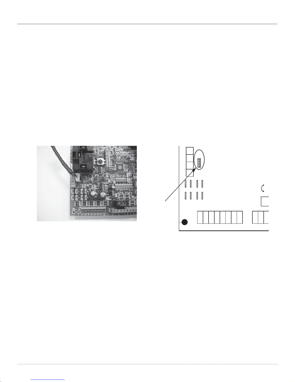
The Service Tool connects to the DXM2 board with a 4-Wire Connector as shown below:
P1
Alarm
O
Y1
Y2
W
G
C
R
AL1
R
C
R
NSB
AL2
JW1
P2
P5
B-
Gnd
A+ 24V
Service tool
connection
DXM2
Board
DXM2
DXM2
Board
Board
1.0 Connection
4
Operating Manual 7602-444 SERVICE TOOL Heat Controller, Inc.
2.0 Menu Structure
System Configuration
Airflow Selection
Option Selection
Unit Configuration
Valve Configuration
Service Mode
Manual Operation
Control Diagnostics
Dipswitch Configuration
Fault History
Clear Fault History
Menu Structure
Start-up Screen
System Configuration Menu
SERVICE TOOL MENU
SYSTEM CONFIG
SERVICE MODE
ACDU01 1.00
SELECT OPTION
SYSTEM CONFIGURATION
OPTION SELECTION
UNIT CONFIG
SELECT OPTION
PREVIOUS SELECT
3.0 System Configuration
Use the System Configuration option on the start-up screen
to adjust critical equipment settings.
The System Configuration information will be automatically
obtained from each communicating control in the system.
Note 1: The Airflow Selection menu (section 3.1) will not be
present if the connected communicating control is configured
for No Blower.
Note 2: The Valve Configuration menu (section 3.4) will
not be present if the connected communicating control is
configured for No Loop Configuration (OTHER).
3.1 AIRFLOW SELECTION
Adjust the airflow settings for each system operating mode
using the up/down arrow buttons. Press the center button to
select each item.
• Airflow Settings (defaults stored in control) -
valid range: obtained from control (in 25 CFM
increments)
• Blower Off Delay (default 60 seconds) – valid
range: 0 to 255 seconds (in 5 second increments)
NOTE 1: The Airflow Settings will only be present if the
connected communicating control is configured for ECM
blower.
5
Heat Controller, Inc. 7602-444 SERVICE TOOL Operating Manual
Option Selection Menu
Unit Configuration Menu
OPTION SELECTION
MOTORIZED VALVE OFF
COMPRESSOR ASCD 0
SELECT OPTION
PREVIOUS SELECT
UNIT CONFIGURATION
CURRENT CONFIG
HEAT PUMP FAMILY
HEAT PUMP SIZE
BLOWER TYPE
LOOP CONFIG
SELECT OPTION
PREVIOUS SELECT
CAUTION!
CAUTION! This is a Commercial option only and does not
alter Residential unit operation.
3.2 OPTION SELECTION
This option allows the configuration of heat pump options to
be modified.
Adjust the Option settings using the up/down arrow buttons.
Press the center button to select each item.
• Motorized Valve (defaults stored in control) –
valid range: Off, On
“On” delays compressor start until the valve is fully open.
• Compressor ASCD (Anti-Short Cycle Delay
(default stored in control) – valid range: 5 to 8
(in 1 minute increments)
NOTE 1: The Compressor Anti-Short Cycle Delay setting
provides equipment protection by forcing the compressor to
wait a few minutes before restarting.
3.3 UNIT CONFIGURATION
Adjust the Unit Configuration settings including Heat
Pump Family, Heat Pump Size, Blower Type, and Loop
Configuration using the up/down arrow buttons. Press the
center button to select each item.
• Heat Pump Family (default stored in control) –
valid range: HTS, HE
• Heat Pump Size (default stored in control) –
valid range: depends on Heat Pump Family setting
• Blower Type (default stored in control) – valid
range: NONE, ECM
• Loop Config (default stored in control) – valid
range: Other, MOD VALVE
3.4 VALVE CONFIGURATION
Configure temperature differentials at the thermostat for
Integrated Variable Speed Water Flow Control units with a
motorized modulating valve.
Adjust the Valve Configuration settings using the up/down
arrow buttons. Press the center button to select each item.
• Heating Delta T (default stored in control) –
valid range: 4 to 12ºF (in 1ºF increments)
• Cooling Delta T (default stored in control) –
valid range: 9 to 20ºF (in 1ºF increments)
NOTE 1: Minimum and Maximum degree values are shown
only when the control is configured with the appropriate
values.
MODULATING VALVE
CONFIGURATION DEG
HEATING DELTA T 8
COOLING DELTAT 15
PREVIOUS NEXT
3.4.1 MODULATING VALVE OFF POSITION
Click Next from section 3.5 to select the off position
value for the modulating valve.
6
Operating Manual 7602-444 SERVICE TOOL Heat Controller, Inc.
4.0 Service Mode
4.1 MANUAL OPERATION
Manual Operation mode allows service personnel to
manually command operation for any of the thermostat
outputs, blower speed, or valve position to help troubleshoot
specific components.
NOTE 1: The ECM Airflow adjustment will not be present if the
connected communicating control (DXM2) is not configured for
ECM (section 3.1).
NOTE 2: The Valve Position adjustment will not be present if
the connected communicating control (DXM2) is configured for
Valve (section 3.4).
4.2 CONTROL DIAGNOSTICS
Control Diagnostics mode allows service personnel to view
the status of all physical inputs, switches and temperature
sensor readings, as well as the operational status of the heat
pump at the thermostat.
Navigate between diagnostic screens using the left/right
arrow buttons.
SERVICE MODE
MANUAL OPERATION
CONTROL DIAGNOSTICS
DIPSWITCH CONFIG
FAULT HISTORY
CLEAR FAULT HISTORY
SELECT OPTION
PREVIOUS SELECT
CONTROL STATUS
TEMPERATURES
LT1 TEMP 38.1
LT2 TEMP 79.9
COMP DISCHARGE 157.7
HOT WATER EWT 121.5
LEAVING AIR 75.1
LEAVING WATER 73.3
ENTERING WATER 78.5
CONTROL VOLTAGE 26.4
ECM BLOWER RPM 550
ECM TARGET CFM 800
ECM BLWR STATIC N/A
PREVIOUS NEXT
CONTROL DIAGNOSTICS
HP SWITCH CL
LOC SWITCH CL
Y1 PHYSICAL INPUT ON
Y2 PHYSICAL INPUT OFF
W PHYSICAL INPUT OFF
O PHYSICAL INPUT ON
G PHYSICAL INPUT ON
H PHYSICAL INPUT OFF
EMERG SHUTDOWN OFF
NIGHT SETBACK OFF
OVR INPUT OFF
PREVIOUS NEXT
MANUAL OPERATING MODE
Y1 COMM OUTPUT OFF
Y2 COMM OUTPUT OFF
W COMM OUTPUT OFF
O COMM OUTPUT OFF
G COMM OUTPUT OFF
H COMM OUTPUT OFF
DH COMM OUTPUT OFF
ECM AIRFLOW 0
PUMP SPEED 0%
TEST MODE OFF
SELECT OPTION
PREVIOUS SELECT
TEST MODE OFF

7
Heat Controller, Inc. 7602-444 SERVICE TOOL Operating Manual
4.3 DIPSWITCH CONFIGURATION
Dipswitch Configuration mode allows the service personnel
to view the status of all dipswitch settings for the connected
communicating control (DXM2/AXM) at the thermostat.
Navigate between configuration screens using the left/right
arrow buttons.
NOTE: The unit control dipswitch settings cannot be changed
from the thermostat or configuration/diagnostics tool.
S1 Dipswitch Status
S2 Dipswitch Status
S3 Dipswitch Status
Fault History
CONTROL CONFIGURATION
DIPSWITCH S1
1 ON UPS ENABLED
2 ON DUAL COMP STG 1
3 ON HEAT PUMP TSTAT
4 ON RV O THERMOSTAT
5 ON DEHUMID OFF
6 ON EH2 AUX HEAT
7 ON BOILERLESS
8 ON SEE DXM2 AOM
PREVIOUS NEXT
CONTROL CONFIGURATION
DIPSWITCH S2
1 ON \ ACCESSORY 1
2 ON ACCESSORY 2
3 ON/
4 ON \ ACCESSORY 2
5 ON ACTIVE W/ COMP
6 ON /
7 ON H DEHUM INPUT
8 ON FACTORY SETTING
PREVIOUS NEXT
CONTROL CONFIGURATION
DIPSWITCH S3
1 ON FACTORY SETTING
2 OFF HWG TEST OFF
3 OFF HWG SP 125
4 OFF HWG DISABLED
JW3 LT1 SETTING WELL
PREVIOUS
4.4 FAULT HISTORY
Fault History mode displays the five most recent stored fault
codes for the connected communicating control (DXM2).
Navigate between control fault codes using the up/down
arrow buttons. Press the center button to view more
information about the highlighted fault code.
HE024 SN - - - - - 0 1 2 3
LAST 5 FAULTS
LT1 LOW WATER TEMP
NO FAULT
NO FAULT
NO FAULT
NO FAULT
NEXT
PREVIOUS SELECT

8
Operating Manual 7602-444 SERVICE TOOL Heat Controller, Inc.
4.4.1 Temperature Conditions
Displays detailed temperature readings that were
recorded at the time the fault occurred
4.4.0 Fault Conditions Menu
4.4.2 Flow Conditions
Displays detailed blower and valve position readings
that were recorded at the time the fault occurred.
4.4.3 Input/Output Conditions
Displays the status of all physical and communicated
inputs, switches, and control outputs that were re-
corded at the time the fault occurred.
FAULT CONDITION MENU
LT1 LOW WATER TEMP
HEAT 1 11:11 AM 11/14
FAULT TEMP CONDITIONS
FAULT FLOW CONDITIONS
FAULT I/O CONDITIONS
FAULT CONFIG COND
FAULT POSSIBLE CAUSES
PREVIOUS SELECT
FAULT TEMPERATURE CONDITIONS
LT1 LOW WATER TEMP
HEAT 1 11:11 AM 11/14
LT1 TEMP 28.1
LT2 TEMP 97.3
HOT WATER EWT 121.5
COMP DISCHARGE 157.7
LEAVING AIR 92.7
LEAVING WATER 34.9
ENTERING WATER 42.1
CONTROL VOLTAGE 26.4
PREVIOUS
FAULT I / O CONDITIONS
LT1 LOW WATER TEMP
HEAT 1 11:11 AM 11/14
TSTAT SAFETY OUTPT
CONV COMM HPS
Y1 Y1 LOC CC
Y2 Y2 CO RV
WW ACC1
OOOUTPT ACC2
GGFAN AL1
HH HWG EH1
OVR DH PUMP EH2
PREVIOUS
FAULT FLOW CONDITIONS
LT1 LOW WATER TEMP
HEAT 1 11:11 AM 11/14
ECM TARGET CFM 800
ECM BLOWER RPM 550
FLOW RATE GPM 6.5
PUMP SPEED 60%
VALVE POSITION 0%
PREVIOUS
VALVE POSITION 0%

9
Heat Controller, Inc. 7602-444 SERVICE TOOL Operating Manual
4.4.3 Configuration Conditions
Displays the status of all dipswitch settings that were
recorded at the time the fault occurred.
4.4.4 Possible Causes
Displays possible causes as to why the fault occurred
4.5 CLEAR FAULT HISTORY
Clear Fault History will clear all fault codes stored in the
thermostat as well as the fault history in any connected
communicating controls (DXM2/AXM).
FAULT CONFG CONDITIONS
LT1 LOW WATER TEMP
HEAT 1 11:11 AM 11/14
S1 S2 S3
1 ON 1 ON 1 ON
2 ON 2 ON 2 OFF
3 ON 3 ON 3 OFF
4 ON 4 ON 4 OFF
5 ON 5 ON
6 ON 6 ON LT1 WELL
7 ON 7 ON LT2 WELL
8 ON 8 ON
PREVIOUS
POSSIBLE FAULT CAUSES
LOW WATER COIL TEMP
LOW WATER TEMP - HTG
LOW WATER FLOW - HTG
LOW REFRIG CHARGE - HTG
INCORRECT LT1 SETTING
BAD LT1 THERMISTOR
PREVIOUS

Date Page # Description
17 Sept., 12 All First Published
Revision History
9/17/12
*97B0106N03*
97B0106N03
Table of contents
Other Heat Controller Accessories manuals


