heatcon! WG User manual

Installation guide
heatcon! System WG
0450000600-1915

2
heatcon! System
Installation guide
Edition: 04.2019
Art:0450000600-1915
We reserve the right to make technical and content changes to this document at all times without prior notice.
EbV assumes no responsibility for any errors or omissions in this document.
All rights to this document and the contained the contained themes and figures are reserved. Reproduction, disclosure to third parties or use of
the content, either in whole or in part, is forbidden without the prior written consent of EbV.
Copyright© EbV - Elektronikbau- und Vertriebs GmbH
All rights reserved

3
1Table of contents
1TABLE OF CONTENTS........................................................................................................................................... 3
2SAFETY................................................................................................................................................................ 4
2.1 GENERAL INFORMATION............................................................................................................................................4
2.2 STRUCTURE OF THE WARNING INSTRUCTIONS ................................................................................................................ 4
2.3 PERSONNEL QUALIFICATIONS......................................................................................................................................4
2.4 THE HOUSING HEATCON WG ..................................................................................................................................... 5
3HEATCON! WG .................................................................................................................................................... 5
4INSTALLATION..................................................................................................................................................... 5
5SUPPLY LINE AT THE HEATCON! WG.................................................................................................................... 6
6CONNECTION TERMINALS................................................................................................................................... 6
7INSTALLATION (PARAMETERIZATION) HEATCON! EC .......................................................................................... 6
7.1 INSTALLATION VIA MMI............................................................................................................................................ 6
7.2 INSTALLATION VIA COMPUTER/LAPTOP ........................................................................................................................7
7.2.1 Preparation ................................................................................................................................................. 7
7.2.2 Installation .................................................................................................................................................. 8
8FINISHING ........................................................................................................................................................... 8
4
2Safety
2.1 General Information
Any person charged with working on the device or system, must have read and understood this manual, especially the
chapter on “Safety”.
Instruction may be necessary, dependent on the professional qualifications of the persons in question.
The relevant accident prevention regulations and other generally accepted safety regulations must be complied with.
2.2 Structure of the warning instructions
Explanation of the warning instructions in this manual:
DANGER
Brief description of the hazard
The signal word DANGER indicates a directly threatening hazard.
Non-observation leads to severe injuries or death.
WARNING
Brief description of the hazard
The signal word WARNING indicates a possible hazard.
Non-observation may result in severe injuries or death.
CAUTION
Brief description of the hazard
The signal word CAUTION indicates a possible hazard.
Non-observation can result in slight or moderate injuries.
ATTENTION
Brief description
The signal word Attention indicates possible property damage.
Non-observation can lead to damage to the device or plant.
NOTE
The signal word note indicates further information about the device or its use.
2.3 Personnel qualifications
The electrical installation, initial operation and servicing of the device may only be performed by qualified electrical
technicians who have been authorised by the operator.
The technicians must have read and understood these operating instructions and follow their procedures.
Requirements to be met by a qualified electrical technician:
•Knowledge of general and special safety and accident prevention regulations.
•Knowledge of the relevant electrical regulations (e.g. DIN VDE 0100 Part 600, DIN VDE 0100-722) plus the
relevant national regulations.
5
•Ability to identify risks and avoid possible hazards.
2.4 The housing heatcon WG
The wall mounting housing heatcon! WG is intended for indoor installation and must not be installed outdoors.
Bevor installation and during use the housing must be checked for damage and thightness and replaced by a specialist
if necessary.
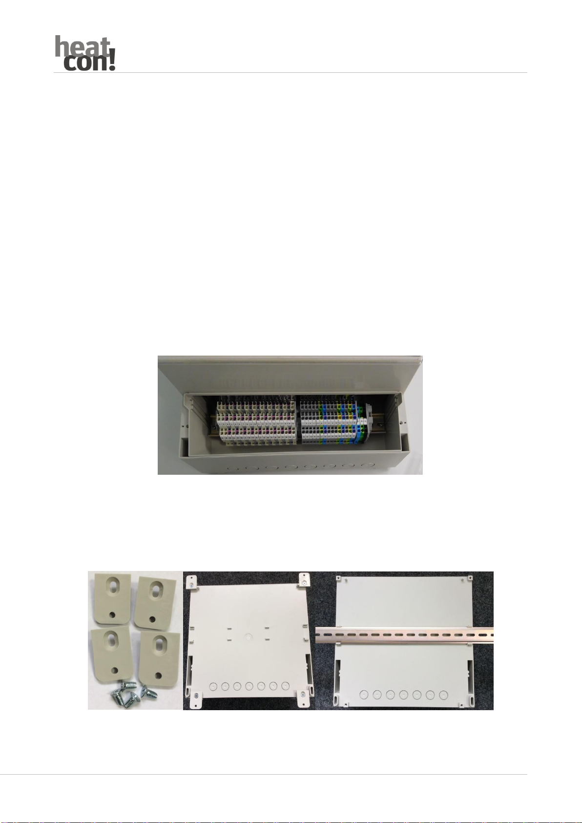
3heatcon! WG
heatcon! WG is a complete set consisting of
- Wall-mounted housing WG 1000
- heatcon! EC 1321 Pro
- heatcon! MMI 200
heatcon! EC and MMI 200 are mounted in the wall-mounted housing. All inputs and outputs of the heatcon! EC are
already wired to the terminals. The installation is carried out comfortably at the easily accessible terminals of the wall
mounting housing.
4Installation
Montieren Sie das Wandaufbaugehäuse an geeigneter Stelle an der Wand. Zur Montage können Sie wahlweise eine
Hutschiene EN 60715 (nicht im Lieferumfang enthalten) verwenden oder die mitgelieferten Wandhalter.

6
ATTENTION
Ensure that no pipes or cables are laid in the wall beneath the mounting location that could be damaged by the
installation.
5Supply line at the heatcon! WG
The electrical installation must be carried out with fixed wiring in accordance with DIN VDE 0100-520.
The supply line must be protected by the emergency heating switch.
6Connection terminals
The sensors, pumps and other components are connected according to the connection diagram in the housing ceiling
of the wall-mounted housing.
The setup wizard of the heatcon! EC preassigns the inputs and outputs. When wiring, pay attention to the desired
functions according to the preassignment of the connection terminals.
DANGER
When wiring, make sure that all live devices are voltage-free.
7Installation (Parameterization) heatcon! EC
The installation of the heatcon! EC is carried out via a menu-driven setup wizard.
7.1 Installation via MMI
After power on, the setup wizard appears in the MMI.
Install the heatcon! EC as described in the short instructions included the device. Detailed installation
instructions for the heatcon! Systems can be found at https://ebv-gmbh.eu/downloads.

7
7.2 Installation via Computer/Laptop
7.2.1 Preparation
For the installation of the heatcon! EC via PC/laptop it is necessary to make the internal connections LAN and USB
accessible.
Open the wall-mounted housing by loosening the screws and carefully lifting off the cover.
Note
Make sure that the existing cables remain in place. If cables are removed, their functionality will later be impaired or
no longer exist.
Plug in a USB extension cable to the USB port and a patch cable (LAN) to the LAN port of the heatcon! EC and lead the
cables into the area of the accessible terminal strips.
Carefully reinsert the housing cover and tighten the screws.

8
7.2.2 Installation
Connect the heatcon! EC with the network. Plug the LAN cable into a free port of the Internet router or a switch.
For installation, the USB port of the heatcon! EC is connected to the USB LAN Adapter from the heatapp! installation
kit. The LAN port is connected to the network card of your laptop.
The details of the installation can be found in the heatcon! system installation guide! Detailed
installation instructions for the heatcon! System can be found under https://ebv-gmbh.eu/downloads.
8Finishing
Finally, put on the cover of the wall mounting housing and tighten the screws.
Table of contents
Popular Heating System manuals by other brands


Haier
Haier HACI-RP Series Installation, use and maintenance manual

OSTBERG
OSTBERG HERU 400-2400T user manual

Monitor Products, Inc
Monitor Products, Inc M2400 Service manual

Monitor
Monitor M2200 owner's guide

Vent-Axia
Vent-Axia Sentinel Kinetic Operation manual

ubbink
ubbink Ubiflux W180 installation instructions