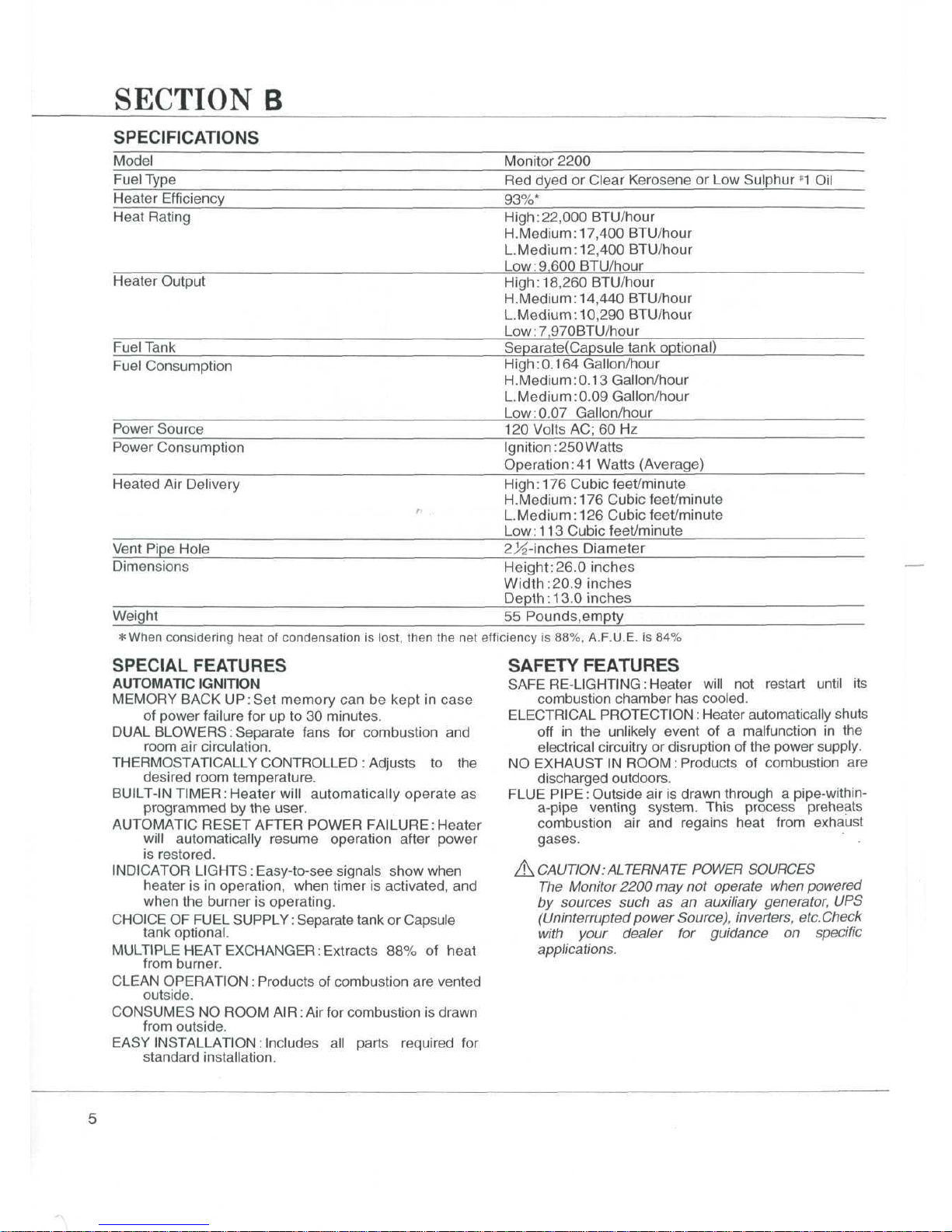
Monitor M2200 User manual


SAFETYALERTSYMBOL
Thesesymbolsappear
as
importantsafetyprecautions
and
should
be
understood
and
followed
bythe
owner
to
assuresafeoperation
ofthe
heater.
For
QuickReferencePage
SECTION
A:A
ImportantCaution
1
SECTION
B
:
Specifications
5
SpecialFeatures
5
Safety
Features
5
SECTION
C:
ToolsNeeded
for
HeaterInstallation
6
Accessories
YouMay
Need
7
FluePipeExtensions
7
SECTION
D:
HeaterInstallation
FluePipeClearances
10
SECTION
E:
Fueling
15
FuelingOptionsAvailable
15
External
TankInstallation
15
EmptyFuelTank
16
Optional
Capsule
Tank
Installation
17
Refueling
19
SECTION
F :
StartingInstructions
;
20
SECTION
G:
Adjusting
RoomTemperature
21
SECTION
H:
Turning
Offthe
Heater
21
SECTION
I :
Relighting
the
Heater
21
SECTION
J :
Programming
the
Heater
22
Setting
the
Day
of
Week
and
the
Time
22
Programming
for
AutomaticHeaterOperation
23
ManualOperation
23
SECTION
K:
Protective
Features
24
Loss
of
Power-AutomaticReset,ChildLock
24
ElectricalFuse
24
OverheatPrevention
•
24
SECTION
L :
Care
ofthe
Heater
25
SECTION
M:
TroubleshootingGuide
27
2004
COPYRIGHT
©
MONITOR
PRODUCTSJNC.

SECTION
A
IMPORTANT
CAUTION
M/VARNING
USE
ONLY
RED
DYED
OR
CLEARKEROSENE
OR
LOW
SULPHUR
#1
OIL.NEVER
USE
GASOLINE,
WHITEGAS,
or
CAMPFUEL.
USEOF
SUCHFUELS
CAN
RESULT
INAN
EXPLOSIVEFIRE
AND
CAUSE
SEVERE
INJURY.
DO
NOT
USE#2
HOMEHEATINGOIL.
KEROSENE
ONLY
GAS
IvCAUTION
1.
Makesure
that
there
isno
fuelleakagefromfuel
tank
and
fuelpipejoint.
2.
Makesure
that
fluepipe(exhaustpipe,
air
supplyhose)
is
connected
properly.

3.
Keepheaterclean
anddonot
store
any
flammableitems
onor
near
the
heater.
4.
Don't
usethe
heater
for
drying
clothes.
5.
Shouldanythingabnormaloccur
inthe
heater,remaincalm,Turn
ItOff(Do
Not
Unplug)
and
contact
yourMonitordealer.
6.
Risk
of
burns.
Fluepipe
and
louver
may
havehighsurface
temperature.

7.
Donot
placeyourself
or
others
too
close
tothe
heater.
8.
Installation
of
heater
in
extreme
humidity
or
dustareas
isnot
recommended.
Any
removal
of
unitparts
or
remodeling
is
strictlyforbidden.
Do
notsitonthe
heater.
Placingornaments
or
plants
onthe
heater
isnot
recommended.
Excess
heat
may
causedamage
to
ornament
or
plant
and
overwatering
or
spilling
of
water
may
causeshock
to,youor
damage
tothe
heater.
10.
In
areas
of
heavysnow
accumulation,
fluepipe
may
need
tobe
installed
higher
to
avoidbeingburied.
In
openareaswithstrongwind,
a
windbreak
maybe
necessary
to
avoidexhaustgasesbeingblown
backinto
the
intake
and
causingpoorcombustion.
Long
Extension
kit
~T
Must
be
higher.
_-
24"min
(60cm)
Snow
-»<

11.
Donot
install
nor
exhaust
the
fluepipe
into
a
crawl
space
or
underneath
floor,nor
into
a
flue
or
chimney.
X
'///////////I
X
-Flue
or
Chimney
12.OPERATING
ALTITUDESHIGHERLIMITS
Thisheater
is
designed
tobe
usednormally
up
to,2330
feet
above
sea
level.
Touse
over2330
feet,
butnot
higher
than
7000
feet,
consultwithyourdealer
on
correct
air
damperuse.
13.OPERATING
TEMPERATURELIMITS
Please
usethe
Monitor
within
the
range
of
temperatures
indicated
bythe
shadedareashown
onthe
graph
below.
OperatingTemperatureLimits
Point
A
InsideAreaTemperature
— 4°F
OutsideTemperature
—
22°F
Point
B
InsideAreaTemperature60°F
OutsideTemperature
—
40°F
-100 2040
Inside
Area
Temperature(°F)

SECTION
B
SPECIFICATIONS
ModelMonitor2200
FuelType
Red
dyed
or
ClearKerosene
orLow
Sulphur
*1
Oil
Heater
Efficiency
93%*
HeatRating
High:22,000
BTU/hour
H.Medium:
17,400
BTU/hour
L.Medium:
12,400
BTU/hour
Low:9,600
BTU/hour
Heater
Output
High:
18,260BTU/hour
H.Medium:
14,440BTU/hour
L.Medium:
10,290
BTU/hour
Low:7,970BTU/hour
FuelTankSeparate(Capsuletankoptional)
FuelConsumption
High:0.164
Gallon/hour
H.Medium:0.13
Gallon/hour
L.Medium:0.09
Gallon/hour
Low:0.07
Gallon/hour
Power
Source
120
Volts
AC;
60
Hz
Power
Consumption
Ignition:
250
Watts
Operational
Watts(Average)
Heated
Air
Delivery
High:
176
Cubic
feet/minute
H.Medium:
176
Cubic
feet/minute
L.Medium:
126
Cubic
feet/minute
Low:
113
Cubic
feet/minute
Vent
PipeHole
2>2-inches
Diameter
Dimensions
Weight
Height:26.0
inches
Width:20.9
inches
Depth:
13.0
inches
55
Pounds,empty
*
When
considering
heat
of
condensation
is
lost,
then
thenet
efficiency
is
88%,A.F.U.E.
is84%
SPECIALFEATURES
AUTOMATIC
IGNITION
MEMORY
BACK
UP:Set
memory
canbe
kept
in
case
of
powerfailure
forupto30
minutes.
DUAL
BLOWERS:Separate
fans
for
combustion
and
room
air
circulation.
THERMOSTATICALLY
CONTROLLED
:
Adjusts
tothe
desiredroomtemperature.
BUILT-IN
TIMER:
Heaterwillautomaticallyoperate
as
programmed
bythe
user.
AUTOMATIC
RESETAFTERPOWER
FAILURE:Heater
willautomaticallyresumeoperationafterpower
is
restored.
INDICATOR
LIGHTS:
Easy-to-seesignalsshowwhen
heater
isin
operation,whentimer
is
activated,
and
when
the
burner
is
operating.
CHOICE
OF
FUEL
SUPPLY:
Separatetank
or
Capsule
tank
optional.
MULTIPLEHEAT
EXCHANGER:
Extracts
88%of
heat
from
burner.
CLEAN
OPERATION:
Products
of
combustion
are
vented
outside.
CONSUMES
NO
ROOM
AIR:
Airfor
combustion
is
drawn
from
outside.
EASY
INSTALLATION:
Includes
all
partsrequired
for
standardinstallation.
SAFETYFEATURES
SAFE
RE-LIGHTING:Heater
will
not
restartuntil
its
combustionchamber
has
cooled.
ELECTRICAL
PROTECTION:
Heaterautomaticallyshuts
off
inthe
unlikelyevent
ofa
malfunction
inthe
electricalcircuitry
or
disruption
ofthe
powersupply.
NO
EXHAUST
IN
ROOM
:
Products
of
combustion
are
dischargedoutdoors.
FLUE
PIPE:
Outside
airis
drawnthrough
a
pipe-within-
a-pipe
ventingsystem.
This
processpreheats
combustion
airand
regainsheatfromexhaust
gases.
£±
CAUTION:ALTERNATE
POWER
SOURCES
The
Monitor2200
may not
operate
when
powered
by
sources such
as an
auxiliary
generator,
UPS
(Uninterruptedpower
Source),
inverters,
etc.Check
with
your dealer
for
guidance
on
specific
applications.

SECTION
C
Before
installing
your
heater,
be
sure
to
check
and
complywithlocal
and
statebuilding
and
electricalcodes
that
may
apply
to
ventedheaters
in
your
area.Permanentwiringmust
be
installed
bya
licensedelectrician.
TOOLSNEEDED
FOR
HEATERINSTALLATION
Check
the
followingcharts
tobe
sure
you
have
allthe
toolsrequired
to
install
yourMonitor2200
Heating
System.
STANDARD
TOOLSAPPLICATION
Phillips
HeadScrewdriver
Installation
of
HeaterParts
SteelTapeMeasure
Taking
Measurements
Penor
Pencil
Marking
Drilling
Location
Exterior
Caulk
Caulking
Between
Packing
and
Wall
Yardstick
or
LongStraightEdgeCheckingAngle
of
Hole
for
FluePipe
Soapy
Water
Lubricating
SleeveHardware
SPECIAL
TOOLS
APPLICATION
ElectricDrillAccommodatingHole
Sawand
Drill
Bit
inchHole
Saw
Attachment
Cutting
Hole
for
FluePipe
Long
1A
inch
Drill
Bit
Drilling
Pilot
Hole
Through
Wall
Level
Checking
Angle
of
Hole
for
FluePipe
andfor
checking
heaterlevel.
Fig.
1

ACCESSORIES
YOUMAY
NEED
Check
the
listbelow
andsee
your
MPI
dealer
for
accessories
youmay
need
or
want
for
installation
of
your
heating-
system.
A\
CAUTION:
Only
use the
flue
pipe supplied
with
the
Monitor 2200,
or the
approved
accessory
kits
available
from
your
Monitor
or
dealer.
ACCESSORY
MediumAdjustableFluePipe
Kit
LongAdjustableFluePipe
Kit
LifterPump
Extra
Short,Short,Medium
or
P/N
8051
P/N
8052
P/N
1101
APPLICATION
For
use
wherewallthickness
isupto
12
/^
inches
For
use
wherewall
thickness
isupto20
inches
For
use
withlargecapacity
tank
wheregravityfeed
isnot
practical
For
use
where"standard"
installation
isnot
practical
Long
Extension
Kitor
ElbowAdapter
Kit
(See
FluePipeExtensions,page
7)
Fitting
and
Tank
For
large
capacity
fueling:
Tobe
dealer
installed
EXTENSION
KIT
LENGTH
Extra
Short
Extension
Kit
Short
Extension
Kit
MediumExtension
Kit
LongExtension
Kit
P/N
82
12
P/N
8004
P/N
8003
P/N
8002
7'/6
to
1 1
!/2
inches
(18.2
to
29.2cm)
11
1/2
to
2014
inches(29.2
to
51
.4cm)
20'/4
to38
inches
(51
.4
to
96.5cm)
38to73
inches(96.5
to
185.4cm)
FLUEPIPEEXTENSIONS
Fourstandardextension
kits
are
available
fromyour
Monitordealer.Most
installations
canbe
made
with
one
of
these
kits.
In
special
cases,
custom
installations
may
be
required.These
maybe
madewith
components
purchasedfromyourdealer.
In
any
installation
the
followinglimitationsMUST
NOT
BE
EXCEEDED:
1.
The
totallength
ofthe
intake
or
exhaustpipeshould
not
exceed
10
feet(3m)with
3
elbows,
13
feet(4m)
with
2
elbows,
or161/2
feet(5m)with
1
elbow.
2.
Theseelbowsshould
include
theone
used
atthe
heater
butnottheoneontheair
supplyhose
northe
integralbends
inthe
fluepipe.(SeeFigure
2)
3.The
correctdamper
as
shown
on
Page
13
must
be
used.

Exhaust
Elbow
Short
Elbow-P/N
4060
Long
Elbow-
P/N
8215
Air
SupplyHose
90°
Joint
Air
Intake
Joint-
P/N
4069FluePipe
Fig.
2
Do
not
count
8

SECTION
D
HEATER
INSTALLATION
Step
1:
Fill
Out
Owner
Registration
Card
Remove
your
ownerregistrationcard
from
the
plastic
envelope
containing
the
owner's
guide.
It
should
be
filled
outand
mailed
as
soon
as
possible.
Step
2:
Check
for
Parts
Before
discardingpackingmaterials,
be
sure
you
have
located
the
following:
FluePipe
Sleeve
Nut
SpillTray
Room
Temp.Sensor(attached
tothe
rear
ofthe
heater)
Cardboard
Template
"STANDARD"
Damper
"EXTENSION"
Damper
Body
Clamp
Rubber
Packing
Joint
Pipe
Cloth
Insulation
Cover
Outer
Flange
Pipe
Holder
Small
Bagof
Screws
Tapping,Type
A -
Tapping,Type
A—
For
securing
sleeve
and
bodyclamp
For
securing
body
clamp
SIZE
Tapping
Tapping
Fig.
3
Step
3:
Choose
a
Location
for
Your
Heater
In
choosing
a
location
for
your
heater,
the
following
guidelinesmust
be
considered:
•
The
heater
MAY
be
installed
on
combustiblefloors.
•
The
areaaround
the
heatershould
be
free
of
obstaclesthatmightinterferewith
the
freeflow
of
air.Allow
the
clearancesshown
in
Figure
4.
12"
(30cm)
51/2"
(13.5cm)
6"
(15cm)
Fig.4
39"
(100cm)
If
the
unit
is
installed
so
that
itis
enclosed
on
both
sides
and
top,
the
following
instructions
shall
be
carried
out.
With
the
side
andtop
clearances
as
shown
in
Fig.
5a,
the
Monitorshall
notbe
placed
so
that
its
front
surface
is
inside
ofthe
enclosure.
6"min
(15cm)
(13.5cm)
6"min
(15cm)
Fig.
5a
Fig.
5b
ZJA
CAUTION:
•
The
heatermust
notbe
installed
ina
fireplace.
•AnAC
wall
outlet
must
be
withinreach
ofthe
heater'spowercord.Extensioncordsmust
notbe
used.
•
The
areaoutsidewhere
the
fluepipewillemerge
should
be
free
of
foliage,fuelstoragetanks
and
flammable
objects.
Air
shouldcirculatefreely
in
the
area.Allow
the
clearancesshown
in
Figure
6on
the
nextpage.
•
The
wallwhere
flue
pipehole
will
becut
should
be
free
of
plumbingpipes,electricalwires,studs,
air
ducts
and
otherobstacles.
NOTE:Use
the
cardboard
template
provided
with
your
heater
for
flue
pipe
location.

FLUEPIPECLEARANCES
Fluepipeinstallationsshouldprovide
for
venting
toan
unconfinedspacethroughwhichthere
isa
freeflow
of
outdoor
air.
Clearances
to
adjacentwalls
or
obstaclesmustcomplywith
the
requirementsshownbelow.
Frontal
Clearance
Combustible
minnnm
IIMII
iiimimiiiii
ACAUTIOIM:
J
Do
not
attachanythingonto
the
outlet
or
of
the
fluepipe.
"
(30cm)
more
5K"
J
(13.5cm)
Body
-
Clamp
J^y
J,
Heater
-*-
-«—
-Wall
Any
construction
3"
aboveFluePipe
(7.5
must
not
come
_,
cm)
within
24"
(60cm)
or
of
frontobstacle
more
«H
24"
(60cm)
—
—
*
or
more
Ib
—
FluePipe
I
or
more
Ground
or
slabsurface
I
1
FrontObstacle
I
I
Overhead
Clearance
rv,mh,
i-tihir
""
»"»
'»"""
12"
(3
or
m
!
Body
Clam
Heate
[
Ocm)
3re
(13.5cm)
3
-
f
—
Non-combustible
~
WaN
Combustible
iiummiiimiiimiii
iiimiiJiimmiJiiiiiiiiiiiiuiiiiiiiN
/
Jr
24"
(60cm)
•J/r
or
more
45°
/
T
-x~X
12"
(30cm)
/
or
more
FluePipe
Ground
or
slabsurface
Side
Clearance
Heater-
Body
Clamp
\
In
A_
Side
obstacle
iiiiiiiiiinmiiii
iiiiiiiiiiiini
ii
18"
(45cm)
or
more
VJJ3
-f
Flue
Pipe
wan
IMPORTANT.
(1)
In
areas
of
heavy
snow
falls,
ground
surface
clearance
must
be
increased
according
to
average
snow
falls,
to
prevent
flue
pipe
from
being
buried.
Long
Extension
(2)
In
open
area
with
strong
wind,
a
wind
break
may be
necessary.
^_
24"min
(60cm)
I
Fig.
6
10

Step
4 :
Drill
a
PilotHole
NOTE:
The
following directions apply
to
'standard
installation.
For
other methods,
follow
instructions
included
with
accessory kits.
Use
the
template
to
position
the
hole
tobe
drilled.
The
"greendot"
indicates
the
exactcenter
ofthe
hole.
Using
an
electric
drill
anda
longdrillbit,make
a
pilotholethrough
the
wall(Figure
7).Be
sure
the
holeextendsthrough
the
outsidewall.
Step
6
:The
FluePipe
istwo
Sections,FluePipe
A
and
FluePipe
B
Install
the
FluePipe
A
FromINSIDE
the
building,
insert
the
fluepipe
A
(with
arrowpointing"up")into
the
hole.Fasten
the
fluepipe
with
the3#8X 3/4
tapping
screws
(Figure9
and
10).
(SeeFigure
for
screwsize
and
application.)
NOTE:
Top
center port
is an
extra exhaust port.
Position
of
hole
—
Template
Fig.
7
tapping
screw
Fig.
9
/!\
CAUTION:
The
opening
onthe
inside
wall
should
be
approximately
1/4
inch higher than
on the
outside
wall
so the
flue
pipe
will
slope
downward
when
installed.
This
will
allow
condensation
to
drain
outdoors.
Step
5:
Cutthe
Hole
forthe
Fluepipe
Using
a
hole
saw
attachment
andan
electric
drill,
cut
a
2/4,
inchdiameterholethrough
the
inner
and
outer
walls(Figure
8).
After
the
hole
is
cut,
usea
straightedge
anda
level
tobe
sure
the
insideopening
is
approximately
%
inch
higherthan
the
outsideopening.
NOTE:
After
cutting
the
inside
wall,
remove
the
insulation.
Make
sure
there
are no
obstructions inside
the
wall,
such
as
electrical
wiring,
water
pipes,
hot
air
ducts, etc.
Room
FluePipe
A
1/4"
Outdoor
T
(6mm)
Fig.
10
Fig.
8
11

Step7:lnstallFluePipe
B
Wall
Thickness:
5-8'/?
inches
1.
Slide
the
outerflange
andthe
rubberpackingonto
Fluepipe
B.(Figure
11)
Rubber
Packing
Outer
Flange
Rubber
PackingOuterFlange
Fig.
11
Flue
Pipe
B
2.
Spreadcaulkingmaterial
onthe
inside
ofthe
rubber
packing
if
required.(Figure
12)
Rubber
Packing
Fig.
12
3.Itis
important
to
keep
the
"UP"mark
onthe
rubber
packing
atthetop
whilescrewing
in
Fluepipe
B.
Hold
the
packing
in
placewhilescrewing
in
Flue
pipe
B
until
itisthe
tight.(Figure
13)
Rubber
Packing
UP"
Fig.
13
Flue
Pipe
B
Wall
Thickness:
v«
-5
inches
1.
Setthe
Sleeve
Nutonthe
FluePipe
B and
turn
the
Sleeve
Nut
counterclockwise.Slide
the
OuterFlange
andthe
RubberPackingonto
the
FluePipe
B.
(Figure
14)
Rubber
Packing
Outer
Flange
Outer
Flange
Flue
Pipe
B
Sleeve
Nut
2.
Spreadcaulkingmaterial
onthe
inside
ofthe
Rubber
Packing
if
required.(Figure
12)
3.Itis
important
to
keep
the
"UP"mark
onthe
Rubber
Packing
atthetop
whilescrewing
inthe
FluePipe
B.
Hold
the
Rubberpacking
in
placewhilescrewing
in
the
FluePipe
B
until
itisthe
tight.
(Figure
13)
4.
Turn
the
Sleeve
Nut
clockwise
and
tighten.
(Figure
15)
Flue
Pipe
A
Rubber
Packing
Outer
Flange
Sleeve
Nut
Flue
Pipe
B
Fig.
15
12

Step
8 :
Install
the
Spill
Tray
Place
the
spilltray
onthe
floorwhere
you
plan
to
locate
yourheater.
Remove
the
screwfrom
the
cabinet
(Figure16).
Position
the
heater
onthe
spilltray
sothe
legs
ofthe
cabinet
fit
into
the
circularindentations
inthe
spill
tray
(Figure
16).
Step
11:
Connect
the
Heater
tothe
FluePipe
Move
the
heatertoward
the
wall,guiding
the
jointpipe
into
the
centerport
ofthe
fluepipe(Figure
18).
Be
sure
the
joint
pipe
is
completely
inserted
into
the
flue
pipe.
Retainers
Fig.
16
Legs
Step
9:
Level
the
cabinet
In
order
for
heater
to
operateproperly.
It
must
be
positioned
ona
levelsurface.Ensureproper
leveling
by
adjusting
each
legandby
using
a
carpenterslevel
to
checkbothside
to
side,
and
front
to
backlevel
condition.
Attach
and
tighten
both
sets
of
retainers
and
screws.
Step
10:
Install
the
JointPipe
At
the
rear
ofthe
heater,slide
the
large
end
opening
of
the
jointpipeinto
the
exhaustportoutlet
ofthe
heater.Besure
the
jointpipe
is
fullyseated.
Slide
the
fabric
coverover
the
jointpipe(Figure
17)
The
o-ringsthatseal
the
jointpipe
maybedryand
tight.
Some
Teflon
grease
or
soapywaterwilleaseinstallation.
Fig.18
Step
12:
Install
theAir
Damper
If
installation
is
standard(that
isno
extensionkits
are
required),
place
theair
dampermarkedwith
a
"STANDARD"
over
theair
intakeflange
onthe
flue
pipe(Figure
19).
Place
the
hose
band
around
theendoftheair
supply
hose.Push
theair
supplyhoseonto
theair
intake
flange
and
secure
the
hosewith
the
hoseband.
FabricCover
Joint
Pipe
Fig.
17
Air
SupplyHose
Fig.
19
NOTE:Do
not
place intake hose onto
metal
capped
exhaust
port.
13

NOTE:
The
"STANDARD" damper
is to be
used with
extension kits
up to 1
bend (90° elbow) with
extension
kit
total length
of
0-73
in. or up to 2
bends
(90°elbows)
with
extension
kit
totallength
of
0-38
in.
or
up to 3
bends
(90 °
elbows) with
no
extension.
The
"EXTENSION" damper must
be
used
installations
that exceed
any of the
limitsabove.
Step15
:
Recheck
the
Heater
Before
proceeding,
check
again
tobe
sure
there
are
no
flammablematerialsclose
tothe
heater.Check
to
be
sure
the
heater
is
level.
Examine
the
fluepipe
tobe
sureconnections
are
tight.
Step13
:
Install
the
FluePipeHolder
Place
the
ring
ofthe
fluepipeholderaround
the
flue
pipe.
The
otherside
ofthe
holderhooks
ina
slot
directly
above
the
joint
pipe
atthe
rear
ofthe
heater
(see
Figure20).
Flue
Pipe
Holder
Fig.
20
Step14
:
Secure
the
Heater
Insert
the
narrowends
ofthe
bodyclampintosockets
on
the
rear
ofthe
heater.
Install
the
adjustmentscrews
and
extend
the
clamp
untiltheytouch
the
wall.Fasten
the
clamp
tothe
wallwith
1 #
SxXtapping
screw.
NOTE:
If use of
body clamp
is not
feasible
or
practical,
the
heater
should
be
secured
by
screws
to
floor through
punched
holes
in
spill
tray.
14

SECTION
E
FUELING
Z?\
WARNING
: Use
onlycrystalclearkerosene(Reddyed
or
clearkerosene
orlow
sulphur
#1
oil).Never
use
gasoline,
whitegas,campfuel
or
otherflammableliquids.
Useof
suchFuels
can
result
inan
explosive
fire
and
causesevere
injury.
Donotuse
*2
HomeHeatingOil.
FUELINGOPTIONSAVAILABLE
Fueling
of
yourMonitor2200
canbe
accomplished
in
oneofthe
followingways.
1.
Optional
Capsule
tank
:
Available
fromyourdealer.
2.
Gravity
Fed
LargeCapacityExternalTank:
Practical
for
largeheatingneedswherebulkdelivery
of
kerosene
is
available.Thissystemshould
be
installed
bya
qualifiedplumber
or
fuelsupply
technician.
3.
LargeCapacityExternalTankwith
Pump:
For
largeheatingneedswhere
a
gravity
fed
system
isnot
practical.
An
electriclifterpump,especially
designed
foruse
withyourMonitor2200heating
system,
is
available
fromyourdealer.
Whenusing
a
gravity
fed
tank
or
pumpingsystem
to
supplyfuel,
the
inletpressure
tothe
heatermust
not
exceed
2.5
psi.
NOTE:lt
is
recommended
to
install
the
fuel
line
on the
left
side
of the
unit,
with
an
appropriate
shut-off
valve,
and
then
across, behind
the
unit,
to the
attachment point
on the
right rear
of the
heater.
NOTE
2:
When
using
a
external
fuel
tank
with
your
Monitor2200
the"Empty"light
will
NOT
signal
an
empty
tank.
Watch
the
gauge
on the
tank
to
avoid
running
out of
fuel.
EXTERNAL
TANK
INSTALLATION-
Gravity
Fed
PREPARATION
AT
HEATER
Stepl:
Remove
thenutatthe
rearlowerside
ofthe
heater.
Collectfueldrainingfrom
the
heaterinto
a
container.
Hold
the
nipplewith
a
wrench
and
loosen
thenut
with
the
otherwrench(seeFigure
21).
Nipple
\
Wrench
Nut
Container
Fig.
21
Step
2:
Insert
the
rubberpluginto
the
disconnectedpipe(see
Figure
22).
If
the
Monitor2200
is
used
to
replace
a
Monitor
22or
422,
pleasenotethat
the
fuelinlet
ofthe
Monitor2200
is
lower
than
theM22or
M422.Some
adjustment
inthe
fuelline
may
be
necessary.
RubberPlug
Bend
the
pipe
aside
Fig.
22
Step
3:
Connect
the
fuel
line
fromExternalTank
as
follows.
15

NOTE:External
tank installations must comply with
the
National Fire Protection Association code
NFPA
31
or
locally applicable codes, such
as the
Uniform
Mechanical
Code, that
are
consistent
with
NFPA
31.
Check
with
your
local
building
official.
To
install
a
largecapacity,gravity
fed
externaltank,
follow
the
instructionsbelow,
and
refer
to
Figure
23for
one
possibleinstallation.
Useofa
qualifiedinstaller
is
recommended.
•
Installation
height
ofthe
bottom
ofthe
fuel
tank
should
be16
inches
or
moreabove
the
floorsurface
on
which
the
heaterstands.
This
ensuresthatinlet
fuel
pressurewill
be
sufficient.
•The
topofthe
fueltank
should
beno
higherthan
8
>2
feet
above
the
floorunder
the
heater.Heights
above
8^2
feetwillexceed
the2.5psi
inletlimit,
anda
pressurereducerwillneed
tobe
installed
at
or
near
the
unit.
•The
horizontallength
of
pipingshould
not
exceed
100
feet
and
shoule
be
free
of
sharpbends
or
obstructions.
•Piping
shouldinclude
no
inverseU-typebends
(to
avoid
air
locks,which
could
block
the
fuel
supply).
•Only
%
inch
OD
coppertubingshould
be
used.
The
tubingshould
be
bentcarefully
to
avoidcrimping.
•A
fuelfilter
is
recommended
foruseonthe
fuelline
near
the
tank,
anda
shut-offvalve
should
be
installed
atthe
tank.
•A
flareadaptor
canbe
used
to
make
a
flaredtubing
connectionbetween
the
unit
andthe
filter
atthe
tank.
•The
fueltankshould
be
located
no
closerthan
3
feet
toa
source
of
heat.
•The
fueltankshouldhave
an
opening
for
filling
on
the
topand
ventwith
a
weather-proof
caponthe
side.
On
sometanks
the
vent
and
fillspout
usethe
sameopening.
When
using
a
gravity
fed
tank
to
supply
fuel,
the
inlet
pressure
tothe
heatermust
not
exceed
2.5
psi.
Outdoor
Fuel
Tank
Shut-off
Valve
Fusible
Link
Valve
Connection
NOTE:
Fuel
tank must
be a
minimum
3
feet
away
from
flue
pipe.
NOTE
2: A
fusible
link
valve
should
be
installed
in
the
fuel
line
behind
the
heater.
Check
local
codes
and
regulations.
/!\
CAUTION: Ensure that there
isno
fuel leakage
from
any of the
fuel line fittings
and
Fig.
23
connections.
EMPTY
FUEL
TANK
If
atany
timeduring
the
operation
of
yourheater
you
find.
•Display
windowshows
"E14".
•No
heat
•No
flame
You
can
assume
youareoutof
fuel.
Shouldthissituationoccur,take
the
followingsteps.
Step
1 :
Turn
the
Heater
Off
Press
the
OperationButton
toputitinthe
"Off"
position.
Step
2 :
Refuel
Refillyourfueltankwithkerosene.
Step
3
:Turn
the
Heater
On
Press
the
OperationButton
toputitin
the
"On"
position.
16

OPTIONAL
CAPSULETANKINSTALLATION
Optionalcapsuletank
kitis
availablefromyourMonitor
dealer.
/h
CAUTION:
The
conversion
ofthe
Monitor2200
foruse
of
the
capsule
can
present
a
Risk
of
ElectricalShock.
The
necessaryElectrical
and
Fuelpipingworkthat
MUST
be
done
ONLY
byan
authorizedServicingDealer.
Step
1:
Be
sure
thenutatthe
rearlowerside
ofthe
heater
is
secured(SeeFigure24).
Step
2:
Remove
the
screws
atthe
FrontCoverAssy,
and
carefully
remove
the
FrontCoverAssy(SeeFigure25).
Nipple
Nut
Fig.
24
Front
CoverAssy.
Fig.
25
Step
3 :
Disconnect
the
plugs
oftheREDand
BROWNwires
marked
"U"
attached
tothe
printedwiringboard
to
enable
the
FuelEmptyFloatSwitch(SeeFigure26).
Printed
WiringBoard
Lead
Wires
I—="•
Color:
Red/Brown
Marking
:
"U"
Plug
For
Open
Circuit
Fig.
26
17

Step
4 :
Remove
the
fuelcap.
Ifthe
fuel
capis
difficult
to
unscrew,
press
the
valve
inthe
center,
and
remove
(See
Figure
27).
Step
6:
Install
the
fuel
filter
tothe
fuelsumptank.
The
FuelFilter
is
included
inthe
optionalcapsuletank
kit
(see
Figure
29).
Fig.
27
Step
5 :
A
siphon
isnot
includedwithyourMonitor2200.
You
may
obtain
one
fromyourMonitor
dealer.
To
operate
a
siphon,insert
the
straighttubeinto
the
kerosene
container.Insert
the
siphon'sflexiblehose
into
the
capsulefueltank(seeFigure28).
Watch
the
fuelgauge
onthe
capsuletankclosely.
As
the
fuelbegins
to
near
the
fulllevel(seeFigure28),
stop
the
flow
by
turning
the
ventknob
ontopofthe
siphon
counter-clockwise.
Remove
the
siphon
slowly
to
allowexcesskerosene
to
drainbackinto
the
container.
Fuel
Filter
Fuel
SumpTank
Fig.
29
"FULL"
Fuel
Level
Fig.
28
Step
7:
Replace
and
tighten
the
fuelcap.
To
insureproperfuel
flow,
be
sure
thecapis
securedcorrectly.
Install
the
tank
with
the
arrowpointing
forward,and
close
the
tankcover(see Figure30).
Fig.
30
NOTICE:Capsule
tank
use is NOT
permitted
Massachusetts
and
Conneticut.
in
18
Table of contents
Other Monitor Heating System manuals
Popular Heating System manuals by other brands

Legalett
Legalett 4000W-24 manual

REVENTON
REVENTON INSPIRO Technical documentation

Viessmann
Viessmann VITODENS operating instructions

Creda
Creda Advanced Control Heating Systems Specification sheet

Mitsubishi Electric
Mitsubishi Electric ecodan EHPT20Q-VM2EA Operation manual

AQUA SZUT
AQUA SZUT TERRAHOT instruction manual

BriskHeat
BriskHeat FFSLE SpeedTrace instruction manual

Horizon Fitness
Horizon Fitness ecoSAVER Installation & operation manual

Carrier
Carrier 40VMZ Installation and maintenance instructions

Sapho
Sapho WTM installation manual

Polypipe
Polypipe Under Floor Heating Systems Technical installation manual

Etherma
Etherma EZ-3600 Installation and operating instructions