Heatcraft Refrigeration Products Beacon II H-IM-79G User manual

H-IM-79G April 2018Part No. 25001401
Beacon II™
Refrigeration Systems
Installation and
Operation Manual
Replaces H-IM-79F (08/17)
™
Table of Contents
Beacon II™ Board Layout .......................................................................... 2
Installation Tips.......................................................................................... 3
Refrigerant Line Brazing ............................................................................ 4
Power Supply............................................................................................. 4
Wiring........................................................................................................ 4
Multiple Evaporator Configuration .............................................................. 5
Box Temperature Control Settings .............................................................. 6
Leak Testing .............................................................................................. 6
Refrigerant Charging ................................................................................. 6
Start-Up Operation................................................................................7-10
Operating Mode Display........................................................................... 10
Programming and Reviewing Settings and Changes ........................... 11-14
Program Review Button
Select Button
Enter Button
Monitoring Items...................................................................................... 13
Monitor Button
Force Defrost Button
Force Service Button
Reset Time Button
Clear/Test Button
Locking The Beacon II Board.................................................................... 14
Status Indicator LED ................................................................................ 15
Low Ambient Operation............................................................................ 15
Pumpdown .............................................................................................. 15
Defrost ...............................................................................................16-17
Alarms .................................................................................................... 17
Error Indicator.......................................................................................... 18
Checking Operation of Expansion Valve...............................................19-20
Power Failures......................................................................................... 20
Spare Sensor Terminals ........................................................................... 20
Checking Sensors.................................................................................... 20
Sensor Resistance/Temperature Table...................................................... 21
System Defaults ...................................................................................... 21
Back Compatibility................................................................................... 22
InterLink Replacement Parts List.............................................................. 23
Operational Limits.................................................................................... 23
Expansion Valve Capacity......................................................................... 24
Diagnostics.........................................................................................24-27
Wiring Diagrams................................................................................. 28-33
Preventive Maintenance........................................................................... 34
Service Record ................................................................................... 35-36

2
Beacon II™Board Layout
©2017 Heatcraft Worldwide Refrigeration
Beacon II™Board
Defrost
Heater
Relay
Evaporator
Fan
Relay
Room
Temperature
Defrost
Temperature
Suction
Temperature
Suction
Pressure
Expansion
Valve
Connection
Selection
Buttons
LED
Display
Terminal
Block
Alarm
Contacts
Spare
Temperature
EXV
Test Pins

3
Installation Tips
• Use a minimum 18 gauge wire for all low voltage
connections.
• The Beacon II board gets its 24 VAC power supply
from a transformer mounted in the electrical end
of each evaporator. On 208-240 volt systems, the
multi-tap transformer is shipped from our factory
wired for 240 volts. If your supply voltage is 208
volt, you must change to the 208 volt tap on the
transformer.
NOTE: On multiple evaporators, since a
transformer is in each evaporator, the
voltage tap must be set on each evaporator.
• Refer to wiring schematic shipped on units for unit
wiring. Schematics in this Installation & Operation
Manual are typical wiring schematics only.
• Program ALL slave evaporators as SLAVES.
• Evaporators are shipped from our factory with a
preset box setpoint temperature of 35°F for air
defrost and -10°F for electric defrost. If your box
setpoint temperature requirements are different,
this must be set using directions outlined under
“Box Temperature” on Page 12.
• The suction line temperature sensor MUST be
removed from the suction line before brazing the
suction tubing. The sensor MUST then be reinstalled
on the suction line after brazing is completed and
the tubing has cooled. Insulate when finished.
• The low pressure switch time delay relay, located in
the condensing unit, must be set to 1 minute.
• If electrical power will be connected prior to
evacuation and charging of system, unplug electric
expansion valve from board until system is ready to
be evacuated, leak tested and charged.
• There are built-in ground connections on the
Beacon II’s four corner brass spacers. Use four
sheet-metal screws to mount the board on the
evaporator for common-mode noise filtering. Make
sure that the evaporator ground terminal is earth
grounded.
Installation
• Some systems may require the crankcase heater
be energized 24 hours prior to start-up. The Beacon
should be de-energized for this period by placing it
in the SERVICE MODE. This is done by pressing the
FORCE SERVICE button twice. To start the system
cooling, press the CLEAR button.
• Room sensors may be left connected on ALL
evaporators. Room sensor must be connected on
the Master Coil.
• A pressure transducer is installed on the evaporator. Do not
leak test system above 150 PSI or damage to transducer
could occur. If leak testing must be greater than 150 psig,
disconnect the transducer from the suction header and
reconnect after testing is complete.
Condensing Unit
The condensing unit control panel contains the relays, contactors,
time delay and a terminal block which is appropriately marked to
match the low voltage wiring connections. A sensor for outdoor air
temperature measurement is installed on the condensing unit.
Condensing unit must be installed using proper refrigeration
practices and codes. Make sure there is sufficient clearances around
unit for adequate air flow and access.
Evaporator Unit
The evaporator contains the Beacon II Controller, electric expansion
valve, pressure transducer, distributor, orifice, transformer and three
sensors. These components are all factory mounted and wired. The
three sensors are factory mounted and provide input to the controller
from the following: defrost temperature, suction temperature, room
temperature
Each evaporator unit must be installed using proper refrigeration
practices and codes. Make sure the piping is correctly sized and
properly routed. It is highly recommended that the liquid and suction
lines be insulated. There must also be good clearance around unit.
See H-IM-UC Installation and Operation manual for more details.
(Available on website).
©2017 Heatcraft Worldwide Refrigeration
4
The electric expansion valve and the suction temperature sensor
on the suction line are factory installed.Care must be taken when
brazing these lines at the evaporator.
Too high a temperature may destroy these components. Heat
absorbing compounds or “wet rags” must be used to protect
the electric expansion valve when brazing the refrigerant line
connections. THE SUCTION LINE SENSOR SHOULD BE REMOVED
BEFORE BRAZING.
Power Supply
The Beacon II board gets its 24 VAC power supply from a transformer
mounted in the electrical end of each evaporator. On 208-240 volt
systems, the multi-tap transformer is shipped from our factory wired
for 240 volts. If your supply voltage is 208 volt, you must change to
the 208 volt tap on the transformer.
VERY IMPORTANT: If the supply voltage to the evaporator is 208
volts, the primary tap of the transformer must be moved to the 208
volt tap.
This must be done for all the evaporators on that system.
If the 24 VAC power supply falls below 18 VAC, the system may
power down and shut off. When the power supply is corrected to 24
VAC, the system will restart after the four minute hold-off period and
resume normal operation.
On Beacon II systems,the main power for the evaporator is supplied
separately from the power supply of the condensing unit. All wiring,
however, must comply with local electrical codes.
Installation
Wiring
Wiring at the unit cooler(s) will be as follows (see wiring diagrams):
• High voltage - There may be high voltage on
the defrost heater relay and the fan relay.
The evaporator is connected to a separate
power supply from the condensing unit.
See unit cooler spec. plate for ampacity.
• Low voltage - 24V Class II control circuit. A total of five
low voltage leads are required to connect the condensing
unit to the evaporator. (See wiring diagram.) Two of these
leads are for connecting the outdoor temperature sensor.
The other three leads are for connecting the compressor
contactor service switch and 2V Common inputs.
All 24 volt wiring must be run separate from the line
voltage wiring.
• Low voltage wiring must be 18 gauge minimum. For low
voltage wiring, maximum distances are:
• Multiple units – The multi-in and multi-out
are the communication connections.
Connection sequence must follow the multi-
out terminal to the multi-in terminal and
the multi-out back to the multi-in terminal in
a daisy chain loop.
• Alarm circuit - The onboard alarm is a dry set of NC
contacts which closes to indicate an alarm or loss of
power. The type and wiring for the alarm is customer
specified. Note that the alarm circuit does not distinguish
or indicate what has caused the alarm.
• All wiring must comply with all applicable codes and
ordinances.
Refrigerant Line Brazing (Caution)
CAUTION: All 24V wiring must be run separate from the line
voltage wiring. Wires/Leads must not touch other component
connection points or power wires to avoid damage to the
board or its components.
Condensing unit to Master evaporator 500ft.
Between evaporators 500ft.
Smart Controller to Master evaporator 1000ft.

5
Installation
If there are multiple evaporators on a system, the program for each
SLAVE evaporator must be changed to identify it as a SLAVE. To do
so, press the “PROGRAM REVIEW” button repeatedly until “SLA”
appears then use the “SELECT” knob to select “YES” and press
“ENTER”. All Beacon II Boards are shipped with the factory default
as a MASTER evaporator. Place all boards in the “SERVICE” mode
while you program the setpoints to avoid errors and alarms which
may cause troubles at startup.
VERY IMPORTANT: This must be done for each slave board, prior
to starting the system.
Multiple Evaporator Configuration (Master/slave)
Up to 4 evaporators can be connected as a master/slave
configuration.
DO NOT remove the room sensor from any of the Beacon II
boards.
PROGRAM
REVIEW SELECT
Each Beacon II board power is supplied by a transformer in the evaporator on which
it is mounted. Do not run any 24 VAC wires between Beacon II boards on the evaporators.
CU
MSSS
M= Master Evaporator S= Slave Evaporator CU = Condensing Unit
This also applies when connected to the optional Smart Controller.

6
Box Temperature Control Settings
• There is an on board room thermostat on the Beacon
II board which can be adjusted to the desired room
temperature. The temperature differential is 2°F.
Temperature Differential
When a system is in the cooling mode and the box
setpoint is 35°F, the system will continue to cool until
the box temperature gets to 34°F. At this point, the
compressor will pumpdown and shut off. The system
will restart cooling when the box temperature has risen
to 36°F.
It is important to note that Beacon II has a minimum
2 minute “ON” time and a minimum 4 minute “OFF”
time. This means that the system will run in the cooling
mode a minimum of 2 minutes even if the setpoint
temperature is met. In applications where the system is
grossly oversized, the box temperature could go below
the differential temperature before the system cycles off.
In the “OFF” cycle the system will be off for a minimum
of 4 minutes even if the box temperature goes above the
differential temperature, before cooling will be restarted.
• The on board room thermostat is factory set at 35°F
for Air Defrost systems and -10°F for electric defrost
system.
Installation
Leak Testing
After all lines are connected, the entire system must be leak
tested. The complete system should be pressurized to not more
than 150 psig with refrigerant and dry nitrogen. The use of an
electronic type leak detector is highly recommended because
of its greater sensitivity to small leaks. As a further check, it is
recommended that this pressure be held for a minimum of 12
hours and then rechecked. For a satisfactory installation, the
system must be leak tight.
Refrigerant Charging
Beacon II systems are shipped standard with a head master valve
(scroll compressor models have a 100 PSI head master valve. All
other models have a 180 PSI head master valve). The maximum
system refrigerant capacity is the receiver capacity as listed in
the sales literature plus the liquid line capacity. Do not add more
refrigerant to the system than 90% of the receiver capacity.

7
Start-Up Operation
Single System With 1 Evaporator
• Check all wiring connections to be sure they are
correct and tight.
• On the condensing unit
- Check the setting of time delay relay.
It should be set at 1 minute {the second
marker).
- Check the adjustable low pressure switch
setting on freezer units. Refer to H-IM-CU. On
some condensing units, the low pressure switch
has a fixed setting and cannot be adjusted.
• Turn power on
Start-Up Operation
CU M
M= Master Evaporator CU= Condensing unit
• On the evaporator
- Use the “PROGRAM REVIEW” button to scroll
through settings.
- Check “rEF” (Refrigerant Type). Factory defaults
are: Air Defrost R-404A, Electric Defrost R-404A.
Change to the refrigerant being used.
- Check “bot”(Box Temperature). Factory
defaults are: air defrost 35°F and electric defrost
–10°F. Change to the desired temperature.
- Review and change other settings if necessary
- See procedures on pages 11-12 for how to
change settings.
8
Single System With Multiple Evaporators
• Check all wiring connections to be sure they are correct
and tight.
• On the condensing unit
- Check the low pressure switch setting on freezer
units. Refer to H-IM-CU (Available on website). On
some condensing units, the low pressure switch has a
fixed setting and cannot be adjusted.
• Turn power on.
• On the MASTER evaporator
- DO NOT REMOVE the room sensor.
- Use the “PROGRAM REVIEW” button
to scroll through settings.
- Check “rEF” (Refrigerant Type). Factory defaults are:
air defrost R-404A, electric defrost R-404A. Change to
the refrigerant being used.
- Check “bot”(Box Temperature). Factory defaults are:
air defrost 35°F and electric defrost –10°F. Change to
the desired temperature.
- Review and change other setting if necessary.
- See procedures on pages 11-12 on how to change
settings.
• On the SLAVE evaporators.
All Beacon II boards are shipped with the factory default as
a "MASTER" evaporator.
- DO NOT NEED TO REMOVE the Room
Sensor on any evaporator.
- Each SLAVE Evaporator must be changed to
identify it as a SLAVE. Use the “PROGRAM
REVIEW” button to scroll until “SLA”appears,
then use the “SELECT” knob to select “YES”then
press “ENTER.”
M= Master Evaporator S= Slave Evaporator CU = Condensing Unit
CU
MSSS
9
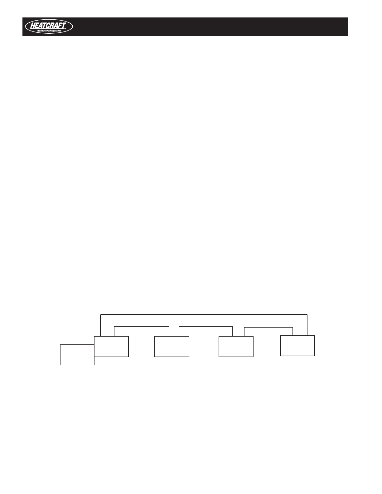
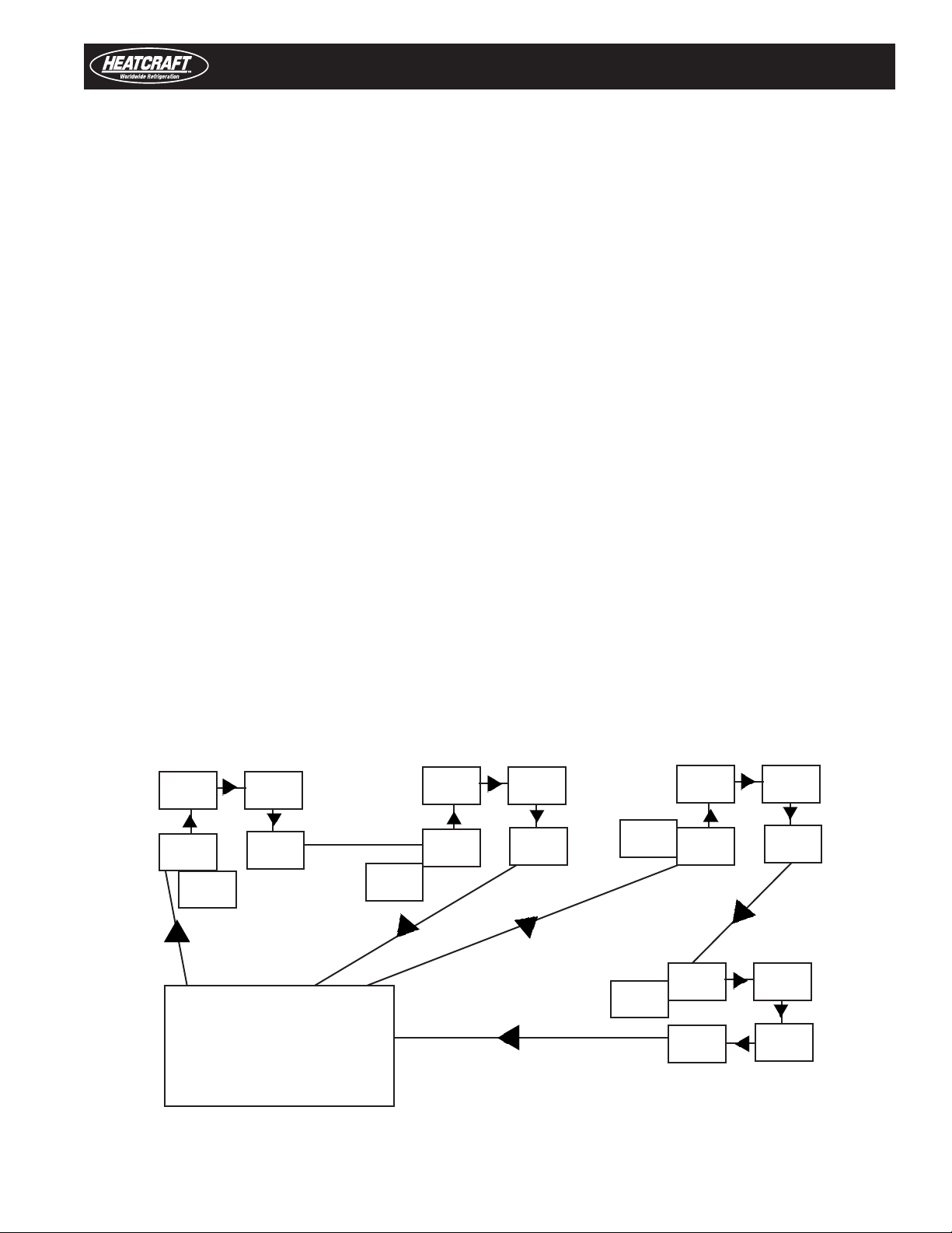
Multiple Systems With Multiple Evaporators
(Requires A Smart Controller)
• Check all wiring connections to be sure they are
correct and tight.
• On the condensing unit
- Check the setting of time delay relay.
It should be set at 1 minute {the second
marker).
- Check the adjustable low pressure switch
setting on freezer units. Refer to H-IM-CU. On
some condensing units, the low pressure switch
has a fixed setting and cannot be adjusted.
• Turn power on
• On the MASTER evaporator
- DO NOT REMOVE the room sensor.
- On the SLAVE evaporators.
All Beacon II boards are shipped with the factory
default as a "MASTER" evaporator.
• Each SLAVE evaporator must be changed to
identify it as a SLAVE. Use the "PROGRAM
REVIEW" button to scroll until "SLA" appears,
then use the "SELECT" knob to select "YES"
then press "ENTER."
• Use the Beacon II Smart Controller to set system
parameters. See Beacon II Smart Controller
installation instructions for more details.
S S
S
M
CU
S S
S
M
CU
S S
S
M
CU
M S
S
S
CU
SMART
CONTROLLER
SYSTEM 1 SYSTEM 2 SYSTEM 3
SYSTEM 4
M= Master Evaporator S= Slave Evaporator CU = Condensing Unit
MULTIPLE SYSTEM CONNECTION
(See Smart Controller instruction manual for more details)
10
Initial Power On
At the initial application of power to the system, the compressor and
the evaporator fans will be in a 4 minute hold-off cycle and will not
start immediately. When there is a call for COOLING, the expansion
valve (EEV) opens, then the compressor is started. The compressor
will then run for a minimum of 2 minutes in the "hold-on" cycle.
(This means that the compressor will run for a minimum of 2
minutes before shutting off even if the box temperature is met).
The LED alternately displays BOX TEMPERATURE and MODE of
operation. On a call for cooling, dLY will show while the expansion
valve is opening. After the compressor starts the LED will alternately
display BOX TEMPERATURE and Coo.
On multiple evaporator systems, the MASTER evaporator will display
BOX TEMPERATURE and Coo. The SLAVE evaporators will display
Coo only.
When the room thermostat setting is satisfied, and if the compressor
ran for at least 2 minutes, the EEV will close and the system will
pumpdown and shut off. The evaporator fans will continue to run.
The LED will alternately display oFF and BOX TEMPERATURE.
Start-Up Operation
When the room sensor detects a rise in temperature of
approximately 2°F, and the compressor has been off for at least 4
minutes, the EEV will open to its last position and the compressor
will start. The valve is then adjusted as necessary to obtain the
setpoint superheat setting. During this time, the compressor will run
for a minimum 2 minutes “hold-on” cycle.
The four minute “HOLD-OFF” can be bypassed and the system
started immediately by pressing the “RESET” button on the Beacon
II board.
Operating Mode Display
oFF - Off
Coo - Cooling
Pdn - Pumpdown
dEF - Defrost
drn - Draining
dLY - Delay
tSt - Test
SEr - Service
IMPORTANT NOTE:
When a board is installed and power is applied to the system, the following initialization steps should be taken for EACH BOARD in system:
1. Press and Hold the "ENTER" button
2. While continuing to hold the "ENTER" button, press and hold the "CLEAR/TEST" button. "888" will display on the LED display.
3. Continue to hold both "ENTER" and "CLEAR/TEST" until "EE?" displays on the LED.
4. Once "EE?" displays, immediately release and the press the "ENTER" again.
5. The board will now re-initialize and return to the normal display.
If "nch" is displayed, then the board did not properly initialize and the steps 1-5 should be re-taken.

11
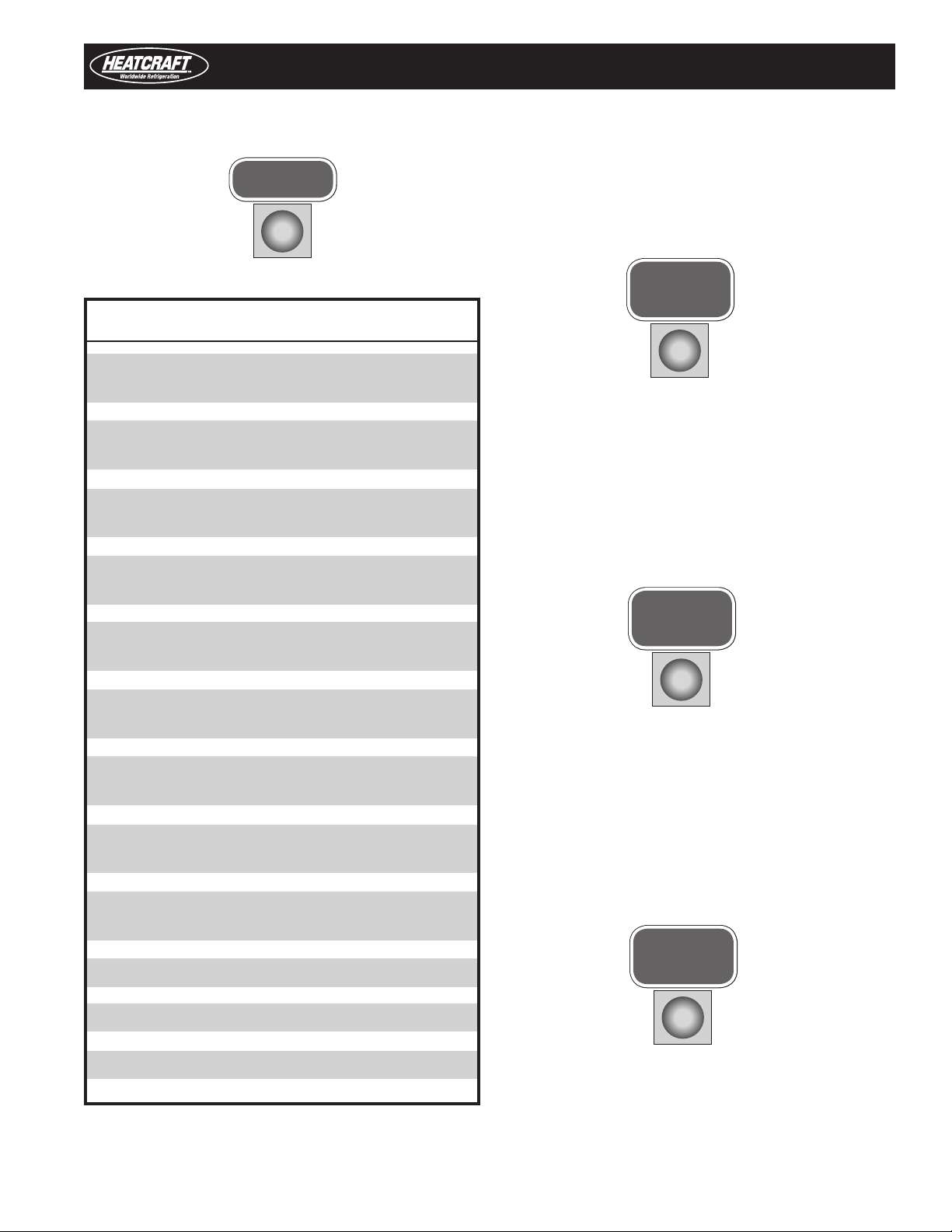
Programming & Reviewing
Programming And Reviewing Settings/Changes
The PROGRAM REVIEW button is used to program, review and
change all program settings for the system.
Press “PROGRAM REVIEW” button. The setpoint item will appear on
the LED. After a few seconds delay, the Setpoint value will display.
Each time the button is pressed a different setpoint item is displayed.
Next, use the “SELECT” knob to change value of setpoint item.
Next, when the desired value is selected, press the “ENTER” button
to place it in program memory. If the “ENTER” button is not pressed,
the value will not be stored in the memory and thus will not be
changed.
A-E - Set Defrost type
(Air or ELE)
rEF - Set Refrigerant type (R-22, R-404A, R-507,
R-407A, R-407C, R-407F, R-448A or R-449A)
bot - Set Box temperature
(-30°F to +70°F)
SUP - Set Superheat
(4°F to 20°F)
SLA - Set Board as a Slave
(Yes or No)
ddF - Demand defrost enable (Yes or No)
dFn - Set Number of defrosts per day
(1, 2, 3, 4, 5, 6, 8,10 or 12 per day)
dFF - Set Defrost Fail-safe time
(10 to 200 minutes)
dFt - Set Defrost End temperature
(40°F to 100°F)
dFS - Set Defrost Delay Start Time
(0.5 Hours to 23.5 Hours)
ALH - Set Alarm High temperature
(-40°F to 90°F)
ALL - Set Alarm Low temperature
(-40°F to 90°F)
ALt - Set Alarm time
(2 to 120 minutes)
F-C - Set Fahrenheit / Celsius
temperature units (°F/°C)
FnS - Off cycle fan stir cycle enable (On or OFF)
“PROGRAM REVIEW” ITEMS
IMPORTANT NOTE:
When a board is installed and power is applied to the system, the following initialization steps should be taken for EACH BOARD in system:
1. Press and Hold the "ENTER" button
2. While continuing to hold the "ENTER" button, press and hold the "CLEAR/TEST" button. "888" will display on the LED display.
3. Continue to hold both "ENTER" and "CLEAR/TEST" until "EE?" displays on the LED.
4. Once "EE?" displays, immediately release and the press the "ENTER" again.
5. The board will now re-initialize and return to the normal display.
If "nch" is displayed, then the board did not properly initialize and the steps 1-5 should be re-taken.
12
Programming & Reviewing
Programming And Reviewing Settings/Changes (cont’d.)
Use the “PROGRAM REVIEW” button to select these items:
• Defrost Type – “A-E” - Selection is made for air
defrost or electric defrost coil. This will automatically set
the system factory defaults for air defrost and electric
defrost. (See default settings.)
• Refrigerant Type - “rEF” - Selection for type of refrigerant
R-22 (22), R-404A (404), R-507 (507), R-407A (47A),
R-407C (47C), R-407F (47F), R448A (48A), R449A (49A).
• Box Temperature - “bot” - Select box temperature
setpoint. Selection range is -30°F to +70° F. Defaults:
Electric defrost -10°F and air defrost +35°F.
• Superheat - “SUP” - Evaporator superheat is controlled by
the board on each evaporator. Each board measures the
evaporator saturation suction temperature and the suction
pressure to determine the superheat. The superheat value
at the evaporator can be changed to ensure a 20°F to 30°F
superheat at the Compressor.
Default: 7°F.
• Evaporator Board: Slave? - “SLA”- On multiple evaporator
systems, each evaporator board has to be programmed
to be a Master or a Slave. Each board is shipped from our
factory set as a Master. You must make this change to
each Slave evaporator. A selection of “YES” is made for this
setting.
The default for each board is a Master, so on Single
Evaporator systems no change is required.
• Demand Defrost Enable – “ddF”– Demand defrost is
available for electric defrost systems only. Selection is
made to enable demand defrost by a selection of “Yes” or
to not enable demand defrost by a selection of “No”. If this
parameter is enabled then parameters dFn and dFS will no
longer be displayed in the menu as they are no longer used.
Default: electric defrost: No
• Number. of Defrost per Day - “dFn” - A selection must
be made for the number of defrosts cycles per day –
1,2,3,4,5,6,8,10 or 12 per day. If no selection is made,
defaults: electric defrost 4 per day and air defrost 2 per day.
• Defrost fail-safe - “dFF” - This is the maximum time allowed
for a coil to remain in defrost. Defrost will be terminated if the
defrost end temperature is not attained when this time has
expired. On multiple evaporator systems, this is controlled by
the Master unit. Each board should have the same setting.
Defaults: electric defrost 30 minutes and air defrost 40 minutes.
• Defrost End Temperature - “dFt” - This is the temperature
at which the defrost will be terminated. Defaults: electric
defrost +60°F and air Defrost +45°F.
• Defrost Delay Start Time - “dFS”- This allows the delay of
the start of the first defrost. Default: 0.0 hours.
• Alarm High Temperature - “ALH” - Temperature at which a
high box temperature alarm will be triggered. This does not
apply during defrost. Defaults: electric defrost +5°F and air
defrost +50°F.
• Alarm Low Temperature - “ALL” - Temperature
at which a Low Box Temperature alarm will be
triggered. Defaults: Electric Defrost -15°F and Air
Defrost +30°F.
• Alarm Time - “ALt” - Time which High Temperature or
Low Temperature condition must exceed before alarm is
triggered. Default: 60 minutes.
• °F/°C - “F-C” - Select units to display temperature.
Fahrenheit or Celsius. Default: Fahrenheit. When °C is
selected, a red dot will appear in the right bottom corner of
the LED display of the Heatcraft Quick Response Controller
board.
• Off cycle fan stir cycle enable – “FnS”– This allows
evaporator fan stir cycling in the off cycle utilizing a
fixed stir cycle timing of 7 minutes on and 5 minutes off.
Selection is made to enable off cycle stir cycling by a
selection of “ON” or to not enable off cycle stir cycling by
a selection of “Off”. Defaults: electric defrost off and air
defrost off
13
Programming & Reviewing
FORCE
DEFROST
RESET
TIME
MONITOR
FORCE
SERVICE
Use the “MONITOR” button to review these items:
SUP - Superheat
(°F/°C)
ESP - Expansion valve steps
(0 to 255 steps)
SCt - Suction temperature
(°F/°C)
SSt - Saturated Suction temperature
(°F/°C)
SCP - Suction pressure at Evaporator
(PSIG/HG)
Odt - Outdoor temperature
(°F/°C)
dFt - Defrost sensor temperature
(°F/°C)
dFS - Time left until next defrost
(hours) (on version 1.8 boards)
dFE - Last Defrost Elapsed time
(minutes)
AC - Board Voltage
SPt - Spare Temperature reading
rEL - Software release program
Use this button to “FORCE DEFROST”. To force a defrost, press the
“FORCE DEFROST” button. The system will pumpdown. The heaters
are then turned on. The display will show “dEF” and room temp.
Use this button to “RESET TIME”. Pressing this button will reset the
time clock in the microprocessor to zero. At initial power up, pressing
this button will bypass the “four minute” hold-off and the system will
start immediately after the expansion valve opens. This display will
show “dLy”.
Use this button to “FORCE SERVICE”. Pressing this button TWICE
will cause the system to pumpdown. The system will remain off until
the “CLEAR” button is pressed. While in the “FORCE SERVICE”, the
LED display will only show “SEr”.
14
Programming & Reviewing
Controller Board
The Heatcraft Quick Response Controller board is lockable to prevent
programmed setting changes by unauthorized personnel. When
locked, the program setpoints cannot be changed.
To lock the setting:
• Press “PROGRAM REVIEW” button.
• Press and hold “MONITOR” button.
• While holding “MONITOR” button,
press “ENTER” button.
• The LED will display Loc.
This will prevent unauthorized personnel program changes. To
unlock, repeat steps above. LED will display “UnL”.
• OFF Box Temp / oFF Box Temperature/ Mode is displayed
All Evaporators
• COOLING
Single Evaporator- Box Temp /Coo Box Temperature/ Mode is displayed
Multiple Evaporators
Master Evap -Box Temp / Coo Box Temperature/ Mode is displayed
Slave Evaps - Coo Operating Mode is displayed
• Pumpdown
All Evaporators Pdn
• DEFROST
All Evaporators dEF
• TEST
All Evaporators tSt
• SERVICE
All Evaporators SEr
• ALARMS A 1 High Box Temp
A 2 Low Box temp
A 3 System Start-up failure
Compressor pumps down and tries to restart
after 4 minutes.
A 4 Input Fault
Box Temp., Suction Temp., Pressure
Transducer open or not installed
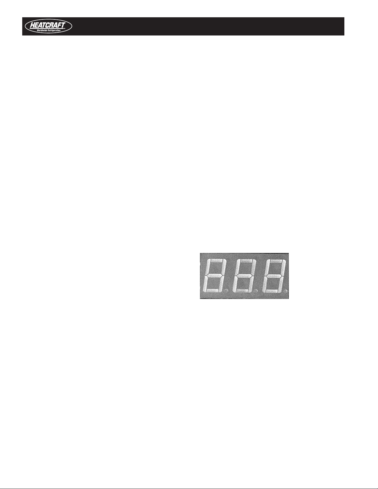
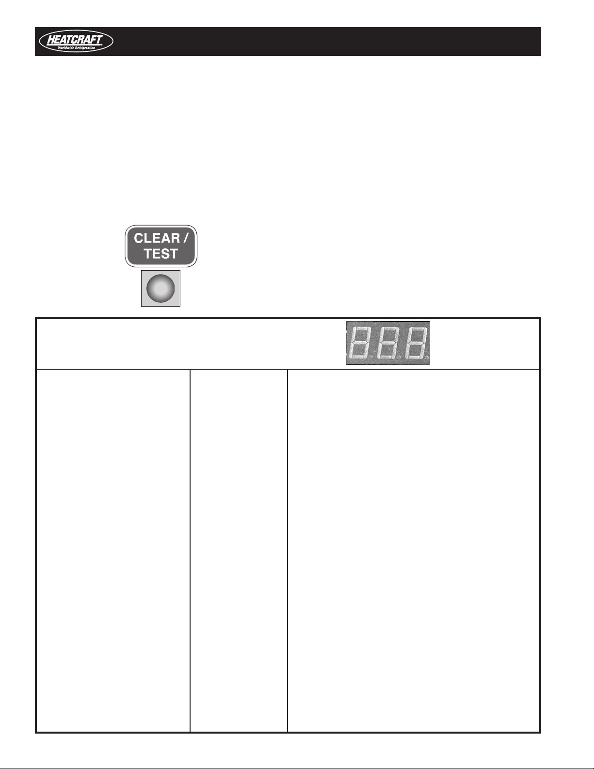
STATUS INDICATOR LED
A RED, three-digit , alphanumeric LED on the Heatcraft Quick Response
Controller board indicates status, alarms and error codes.
Programming And Reviewing Settings/
Changes (Cont’d.)
Use this button to “CLEAR/TEST”. Pressing this button ONCE will
return the LED display to the default display. With the system in the
OFF mode, pressing and holding this button will start the “TEST”
mode. In the “TEST” mode, it will cycle through each output for 10
seconds. The display will only show “tst” during “TEST” mode.
Test mode will automatically terminate after 3 sequences.
Locking The Heatcraft Quick Response

15
STATUS INDICATOR LED
• ERRORS E 1 - Room temperature sensor shorted, open or not installed
E 2 - Defrost temperature sensor shorted, open or not installed
E 3 - Suction temperature sensor shorted, open or not installed
E 4 - Suction pressure transducer shorted, open or not installed
E 5 - Outdoor temperature sensor shorted
E 6 - Low superheat during cooling
E 7 - Compressor shutdown
{high or low refrigerant pressure or low oil pressure)
E 9 - Multi-in/Multi-out wiring error
• OTHERS Loc - Board is locked. Settings cannot be changed
UnL - Unlock the board settings
Low Ambient Operation
All units are shipped standard with head master valves. (Scroll
compressor units have a 100 PSI head master valve and all other
systems have a 180 PSI head master valve.) Condensing units
with multiple condenser fans will have one or more fans cycle on
pressure fan cycling switch.
An adjustable time delay relay, factory set at 1 minute, is wired
across the low pressure switch (LPS). In cold ambient, this allows
time for the suction pressure to build up and prevent nuisance
tripping of the LPS.
When any of these two conditions occurs, the system will turn
off and not restart until there is a call for cooling or a periodic
pumpdown.
Pumpdown
At the end of each cooling cycle, when the box temperature is met,
the Beacon II system will pump down.
To pumpdown, the EEV closes and the board displays “Pdn” until
one of the following occurs:
• The low pressure switch opens
• The suction pressure at the evaporator
is 4 psig
• A total of two minutes has elapsed
Status Indicator LED
Periodic Pumpdown
While in the OFF cycle, if there isn’t a call for cooling (Box setpoint
temperature is met) but:
• The evaporator suction pressure has risen
to 10 psig
• The low pressure switch has closed
The system will initiate pumpdown. This periodic pumpdown will
occur at 4 minute intervals when these two conditions are met.

16
Defrost Delay Start Time
Example: The system is first powered up at 8:00 AM and is
programmed for 4 defrost per day. The user would like the first
defrost at 10:00 AM. To accomplish this, use the “PROGRAM
REVIEW” button to scroll to dFS. Use the “SELECTOR” switch to
select 2 hours delay start, then press “ENTER.” The 1st defrost will
now occur at 10:00 AM and then a defrost will occur every 6 hours
thereafter.
Time Remaining Until Next Defrost
To find out how much time is left until the next defrost is scheduled,
use the “MONITOR” button to scroll to dFS. The time displayed will
be how much time until the next scheduled defrost.
Defrost Schedule In Memory
Beacon II does not have a real time clock but it keeps track of the
time that has elapsed in its memory. It also keeps in memory the
number of defrosts scheduled and how much time has elapsed
between defrosts. If a power failure occurs, when power is restored,
Beacon II remembers how many defrosts are scheduled and it
remembers how much time was left until the next defrost. It will
then defrost based on this timing. So, if the power failure lasted 15
minutes, the defrost schedule will be off by 15 minutes.
Resetting Defrost Schedule
When a power interruption causes a severe lag in the defrost
schedule, the defrost schedule can be reset in the following manner.
First, press the reset time button on the board to zero out the internal
counters. Then, program the appropriate defrost delay start time for
the next desired defrost period. The defrost schedule will be correct
until you have another power outage.
Service Defrost
Service Mode
A single pole, single throw switch (SPST) is supplied in each
condensing unit for shutting off the system. Closing the "SERVICE"
switch in the condensing unit will cause the system to pumpdown
and shut off. "SEr" will be displayed on the Beacon board LED and
"SERVICE" is displayed on the Smart Controller LCD display. The
evaporator fan and heaters will be de-energized in the Service Mode.
The system will not restart until the SPST switch is placed in
the “NORMAL” or “OFF” position.
OR
A remote "SERVICE" switch can be added to the Beacon II board
across the "Ser" and "C" connections of the terminal block. It will
operate in the same manner as the switch above.
OR
The system can be pumped down by pressing the "SERVICE" button
twice. To restart the system, press the "CLEAR" button.
OR
The system can be pumpdown for service by closing the liquid line
service valve in the condensing unit, then closing the suction line
service valve when the system trips on the low pressure switch.
In order for air defrost evaporator fan motors to cycle off during
"SERVICE" mode, the fan motors must be wired through the fan
relay on the Beacon II board.
Defrost
Defrost Timing
When power is first applied to the system, its timer starts counting
time. If 4 defrost are programmed, it will initiate a defrost every 6
hours from when power was first applied. Beacon II does not have
a real time clock. Beacon II does provide the ability to delay the
starting of the first defrost.

17
Electric Defrost Mode
When a defrost is initiated, the EEV closes, the system is allowed to
pumpdown and shut off. The evaporator fans are cycled off and the
defrost heaters are energized.
On multiple evaporator systems, all controllers must terminate their
defrost, either on temperature or fail-safe time, before the master
controller will end the defrost cycle.
There is a 2 minute condensate drain-down period after which the
system is started for a refreeze period. The evaporator fan stays
off (fan delay). The refreeze period will last until the evaporator
suction temperature is at 28°F or 3 minutes has elapsed. After
this sequence, the system is back in the refrigerating mode and
evaporators fans are now running.
Air Defrost Mode
The sequence is the same as for electric defrost except that there
are no heaters and the evaporator fans run continuously. If the air
defrost for motors are wired through the fan relay on the board, they
will remain energized during defrost mode.
Alarms
Beacon II provides a set of dry contacts for use in signaling an alarm.
These contacts can be connected to a light, a buzzer, a bell etc.,
which will be activated when an alarm condition occurs. When the
Beacon II is energized, the alarm contacts are OPENED. When an
alarm condition is detected, the contacts are CLOSED.
Conditions under which the alarm contacts will close are:
• High Box Temperature – LED Display:
A1 - Room temperature has exceeded
the Alarm High ALH value for the Alarm
time ALt programmed.
• Low Box Temperature - LED Display:
A 2 - Room temperature has dropped
below the Alarm Low ALL value for the
Alarm time ALt, programmed
Defrost / Alarms
Clearing Alarms
Alarms A1 – High Box Temperature and A 2 – Low Box Temperature
will clear automatically if the Box Temperature decreases or
increases to below or above the Alarm setpoint temperature. Placing
the system in the "SERVICE MODE" or turning off power will clear
the A 3 Alarm. Replacing the Room Sensor, Suction Sensor or
Pressure Transducer will clear the A 4 Alarm.
• System Start-up failure - LED Display: A 3 - Compressor
pumps down and tries to restart after 4 minutes. After 4
unsuccessful attempts to restart, the alarm code A 3 is
displayed. System continues trying to restart.
• Input Fault – LED Display: A 4 - Box Temp., Suction Temp.,
Pressure Transducer open or not installed.
• Power failure – Loss of power to the Evaporator
A 1 High Box Temp
A 2 Low Box Temp
A 3 System Start-up failure
Compressor pumps down and tries to restart after 4
minutes
A 4 Input Fault
Box Temp., Suction Temp., Pressure Transducer open
or not installed
Power Failure
Alarm Codes

18
Error Indicator
Air Defrost fan motors must be wired through the fan relay on the
Beacon II board for this to be effective on Air Defrost systems. The
entire system will be shut off and remain off until the SPST switch is
opened.
ERROR CODES
E1 - Room temperature sensor shorted,
open or not installed
E2 - Defrost temperature sensor shorted,
open or not installed
E3 - Suction temperature sensor shorted,
open or not installed
E4 - Suction pressure transducer shorted,
open or not installed
E5 - Outdoor temperature sensor shorted
E6 - Low superheat
E7 - Compressor shut down
(high or low pressure switch open or
oil pressure switch open)
E9 - Multi-in/multi-out wiring error
Error Indicator LED
At initial power up, each Heatcraft Quick Response Controller board
checks for system errors. The system error check involves checking
the various temperature sensors to determine whether any of these
sensors are shorted or open.
The system will pumpdown and cycle off and will not restart until
the fault is cleared or the circuit breaker reset, for the following
conditions:
- Suction sensor shorted, open
or not installed
- Room temperature sensor shorted
or not installed
- Pressure Transducer open
or not installed
The system will pumpdown, cycle off and try to restart for these
faults. Each try will be after the 4 minutes
"Hold Off" period, for the following fault conditions:
- High pressure or low pressure cutout
- Oil pressure
After the fourth try, the Alarm contacts will be closed and an alarm
message displayed on the LED. To clear this condition, the system
should be cycled through the "SERVICE MODE" after the correction
is completed.
Evaporator Fans Shut Off
In some installations, it is desirable to shut off the evaporator fans
periodically. This is easily accomplished on Beacon II by wiring
a single pole, single throw switch (SPST) between the terminals
marked “SER” and “C” on the Beacon II board. Closing this switch
will cause the system to pumpdown and shut off.

19
Checking Operation Of Expansion Valve (EEV)
To check if the expansion valve is closing properly:
Install a pressure gauge-set to suction line at the condensing
unit. With the system running, close the valve on the liquid line,
at the condensing unit. The system should pumpdown and shut
off on the low pressure switch (LPS). If the system does not
pumpdown and trip on the LPS, then the compressor valves are
weak and needs to be changed.
After the system pumps-down and trip on the LPS, put the
system in the service mode. This will cause the expansion valve
to close. Open the valve on the liquid line, at the condensing
unit. The suction pressure reading on the gauge set should not
increase. If the suction pressure increases then the expansion
valve is leaking and should be changed.
The expansion valve position can be monitored from the LED display
pressing the “MONITOR” button and scrolling to ESP. This will
indicate the number of steps the valve is open.
Checking Operation of Expansion Valve
If the expansion valve is suspected of not functioning properly, the motor windings resistance should be measured. This is a bipolar motor
with two windings. Measure the resistance at the pins, on top of the valve, between locations A and B or C and D.
(Note that the pins are not labeled A, B, C, D. This labeling is just for reference).
This can also be checked by using the EXV test pins on the board.
This is indicated by a 0 to 5 volts DC signal. At 0 volts the valve is
closed and at 5 volts the valve is fully open. At values between 0 and
5 volts, the valve will be opened proportionately.
Use the “MONITOR” button to display “SCP”Evaporator Suction
Pressure. Record the pressure displayed. Start the system and
observe the pressure displayed. If the pressure does not increase,
the expansion valve could be defective.
If the system is running, use the “MONITOR” button to display “SCP”
Evaporator Suction Pressure. Record the pressure displayed. While
the system is running, press the “FORCE SERVICE” button. Observe
the pressure while the system is pumping down. The pressure
should decrease. If it does not, this indicates a defective valve.
Expansion Valve Motor Winding Resistance
Resistance reading at 150 at 75° F
“C” is largest spade
Measuring resistance between locations A and C or B and D will
always show “Open” because these locations are between the motor
windings.
When the valve is opening or closing, the voltage measured between
A and B or C and D should be between 20 to 22 VAC.
Measuring the DC volt of the EXV TEST pins, on the board, will also
indicate if the expansion valve is open or close. 0 volts DC indicates
the valve is closed. 5 volts DC indicates the valve is fully open. A
value between 0 and 5 volts indicates how much the valve is open
or close.

20
Power Failures
In the event of a power failure, Beacon II will automatically close the
expansion valve to prevent refrigerant from migrating throughout the
system. After power returns, with 24 VAC at the board, the system
will restart in the cooling mode after the four-minute hold off period.
Spare Sensor Terminals
Beacon II provides a set of input terminals for customers who may
want to monitor an additional temperature or items such as Product
Temperature. This input terminal requires a signal from a thermistor
which meets the temperature/resistance values in Table 1 on page
21.
If a product temperature simulator is used, it must meet the
resistance/temperature specification listed in Table 1. The
temperature range for this input is –30°F to 140°F. Sensors on the
Beacon II system, as supplied, will not simulate product temperature.
This input can be monitored on the LED display by using the
“MONITOR” button and scrolling to SPt. The values displayed will
be the temperature of the spare sensor.
Power Failures
Checking Sensors
DO NOT REMOVE SENSORS FROM EVAPORATORS FOR CHECKING.
Use the monitor button to display the value the sensors are reading
on the LED (suction temperature SCt, defrost temperature dFt, or
room temperature). Compare this value to the measured value with
a thermometer at each of these points. If they do not match, change
the sensor.
OR
The sensors can be checked for their proper operation by placing it
in a cup of ice water. Stir the ice water and measure the resistance
of the sensor. At 32°F the resistance should be 32,650 ohms. If it is
higher or lower by 1,000 ohms approximately, the sensor should be
replaced.
This manual suits for next models
2
Table of contents


 Installation and operation guide")


