KICK ASS KABTSWPANEL-8 User manual

BLUETOOTH
SWITCH PANEL
8 GANG
USER GUIDE
V0.6
KABTSWPANEL-8

TABLE OF CONTENT
1
3
4
4
5
6
6
7
8
8
10
12
14
15
16
17
18
19
- - - - - - - - - - - - - - - - - - - - - - - - - - - - - - - - - - - - - - - - - - - - - - - -
- - - - - - - - - - - - - - - - - - - - - - - - - - - - - - - - - - - - - - - - - - - - - - - -
- - - - - - - - - - - - - - - - - - - - - - - - - - - - - - - - - - - - - - - - - - - - - - - -
- - - - - - - - - - - - - - - - - - - - - - - - - - - - - - - - - - - - - - - - - - - - - - - -
- - - - - - - - - - - - - - - - - - - - - - - - - - - - - - - - - - - - - - - - - - - - - - - -
- - - - - - - - - - - - - - - - - - - - - - - - - - - - - - - - - - - - - - - - - - - - - - - -
- - - - - - - - - - - - - - - - - - - - - - - - - - - - - - - - - - - - - - - - - - - - - - - -
- - - - - - - - - - - - - - - - - - - - - - - - - - - - - - - - - - - - - - - - - - - - - - - -
- - - - - - - - - - - - - - - - - - - - - - - - - - - - - - - - - - - - - - - - - - - - - - - -
- - - - - - - - - - - - - - - - - - - - - - - - - - - - - - - - - - - - - - - - - - - - - - - -
- - - - - - - - - - - - - - - - - - - - - - - - - - - - - - - - - - - - - - - - - - - - - - - -
- - - - - - - - - - - - - - - - - - - - - - - - - - - - - - - - - - - - - - - - - - - - - - - -
- - - - - - - - - - - - - - - - - - - - - - - - - - - - - - - - - - - - - - - - - - - - - - - -
- - - - - - - - - - - - - - - - - - - - - - - - - - - - - - - - - - - - - - - - - - - - - - - -
- - - - - - - - - - - - - - - - - - - - - - - - - - - - - - - - - - - - - - - - - - - - - - - -
- - - - - - - - - - - - - - - - - - - - - - - - - - - - - - - - - - - - - - - - - - - - - - - -
- - - - - - - - - - - - - - - - - - - - - - - - - - - - - - - - - - - - - - - - - - - - - - - -
- - - - - - - - - - - - - - - - - - - - - - - - - - - - - - - - - - - - - - - - - - - - - - - -
WARNING & SAFETY INSTRUCTIONSWARNING & SAFETY INSTRUCTIONS
WHAT’S INCLUDEDWHAT’S INCLUDED
PRODUCT FEATURESPRODUCT FEATURES
SPECIFICATIONSSPECIFICATIONS
DIMENSIONSDIMENSIONS
CONTROL BOX INSTALLATIONCONTROL BOX INSTALLATION
FIXED MOUNT BRACKET OPTION FIXED MOUNT BRACKET OPTION
FLUSH MOUNT OPTION FLUSH MOUNT OPTION
SWITCH PANEL MOUNTINGSWITCH PANEL MOUNTING
ADJUSTABLE MOUNT BRACKET OPTION ADJUSTABLE MOUNT BRACKET OPTION
FLUSH MOUNT OPTION FLUSH MOUNT OPTION
WIRING INSTALLATIONWIRING INSTALLATION
SWITCH PANEL INDICATIONSWITCH PANEL INDICATION
BACKLIGTH COLOR & BRIGHTNESSBACKLIGTH COLOR & BRIGHTNESS
SWITCH MODE PROGRAMINGSWITCH MODE PROGRAMING
SMART PHONE CONTROL AVAILABLESMART PHONE CONTROL AVAILABLE
FCC COMPLIANCE STATEMENTFCC COMPLIANCE STATEMENT
WARRANTYWARRANTY
WARNING & SAFETY INSTRUCTIONS
WHAT’S INCLUDED
PRODUCT FEATURES
SPECIFICATIONS
DIMENSIONS
CONTROL BOX INSTALLATION
FIXED MOUNT BRACKET OPTION
FLUSH MOUNT OPTION
SWITCH PANEL MOUNTING
ADJUSTABLE MOUNT BRACKET OPTION
FLUSH MOUNT OPTION
WIRING INSTALLATION
SWITCH PANEL INDICATION
BACKLIGTH COLOR & BRIGHTNESS
SWITCH MODE PROGRAMING
SMART PHONE CONTROL AVAILABLE
FCC COMPLIANCE STATEMENT
WARRANTY

1
SAVE THESE INSTRUCTIONS - THIS MANUAL CONTAINS IMPORTANT SAFETY
INSTRUCTIONS FOR THE KICKASS BLUETOOTH SWITCH PANEL.
DO NOT OPERATE THE SYSTEM UNLESS YOU HAVE READ AND UNDERSTOOD THIS
MANUAL AND THE SYSTEM IS INSTALLED AS PER THESE INSTALLATION
INSTRUCTIONS. KICKASS RECOMMENDS THAT THE SYSTEM BE INSTALLED BY A
SUITABLY QUALIFIED PERSON.
DISCLAIMER: KICKASS accepts no liability for any injury, loss or property damage which may
occur from the improper or unsafe installation or use of its products.
WARNING
1. THIS PRODUCT SHOULD NOT BE USED FOR ANY MEDICAL PURPOSES, LIFE
SUSTAINING EQUIPMENT, SAFETY APPLICATIONS, OR ANY APPLICATION WHERE
EQUIPMENT FAILURE CAN CAUSE INJURY, DEATH, FIRES OR ANY OTHER
HAZARD.
2. READ ALL MANUALS, AND THESE WARNINGS AND INSTRUCTIONS CAREFULLY
BEFORE USING THIS PRODUCT. FAILURE TO OBSERVE THESE INSTRUCTIONS
PROPERLY, OR IMPROPER USE OF THE PRODUCT OR MOBILE APP COULD
RESULT IN PERSONAL INJURY, INCLUDING DEATH OR DAMAGE TO PROPERTY.
CAUTION
1. The Switch Panel App. allows modification to the system functionality of your
KickAss Bluetooth Switch Panel; only use this app. if you have read and fully
understand all the instructions in this manual
2. Risk of explosive gases: Working in the vicinity of a battery is dangerous.
Batteries may generate explosive gases during normal operation. For this
reason, it is of utmost importance that you follow the instructions of the battery
manufacture each time you use the system. Prevent flames and sparks, and
provide adequate ventilation, especially during charging or discharging.
3. Do not install this product in the same compartment where flammable materials,
such as petrol/gasoline or Liquefied Petroleum Gas (LPG) are stored.
4. The system should not be used by persons under the age of 18, or those with
reduced physical, sensory or mental capabilities, or lack of experience and
knowledge, unless they are supervised or have been instructed on how to use
the appliance by a person responsible for their safety. Persons under the age of
18 should be supervised.
WARNING & SAFETY INSTRUCTIONS

2
5. Do not operate the Bluetooth Switch Panel or the Mobile Application to control
movable items whilst under the influence of alcohol or drugs. Doing so may result
in personal injury or property damage.
6. Do NOT alter or disassemble the system under any circumstances. All services
or repairs must be returned to KickAss for repair. Incorrect handling or
reassembly may result in a risk of electric shock or fire and may void the unit
warranty.
7. Cable and fuse sizes are specified by various codes and standards which
depend on the type of vehicle the system is installed into. Selecting the wrong
cable or fuse size could result in harm to the installer or user and/ or damage to
the system componetents or other equipment installed in the system. For this
reason, do not replace fuses with ones of higher amperage ratings. The installer
is responsible for ensuring that the correct cable and fuse sizes are used when
installing this system.
8. Do not drop metal tools onto a vehicle battery. Doing so might cause the battery
to spark or might short-circuit the battery or other electrical parts that may cause
an explosion. Remove personal metal items such as rings, bracelets, necklaces,
and watches before working with a vehicle battery. A vehicle battery can produce
a short-circuit current high enough to weld a ring or the like to metal, causing a
severe burn.
9. NEVER SMOKE OR ALLOW A SPARK OR FLAME NEAR A BATTERY AS
THESE MAY CAUSE THE BATTERY TO EXPLODE. TO REDUCE THE RISK
OF A SPARK NEAR A BATTERY WHEN CONNECTING THE BATTERY
INSTALLED IN A VEHICLE ALWAYS DO THE FOLLOWING:
10. Wire all cable connections to the Control Box before making connection to the
vehicle battery. The Battery Output (positive) must be connected first, followed
by the Ground (chassis) terminal. The chassis connection should be made away
from the battery and fuel lines.
11. Do not use this product to control safety critical devices or those that could cause
harm if operated remotely (for example fume exhaust fans or lifters). Only
operate devices with moving parts when you have a clear line of sight to the
moving parts.
12. Ensure that the Display is not mounted in vehicle head-impact zones. Doing so
may result in injury to the driver and/or passenger in the event of an accident.
13. Ensure the Display is not mounted where it may distract the driver of the vehicle.
Distracting the driver may result in an accident.
14. Risk of damage to the system. Do NOT connect a load negative (-) to the chassis
AND to the applicable negative (-) output channel as this may cause damage to
the Distribution Box under some circumstances. Connect to the applicable
negative (-) output channel OR a suitable chassis grounding point to avoid
damage.
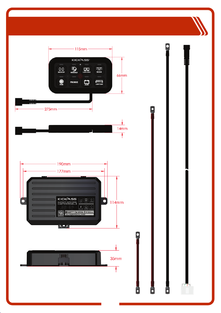
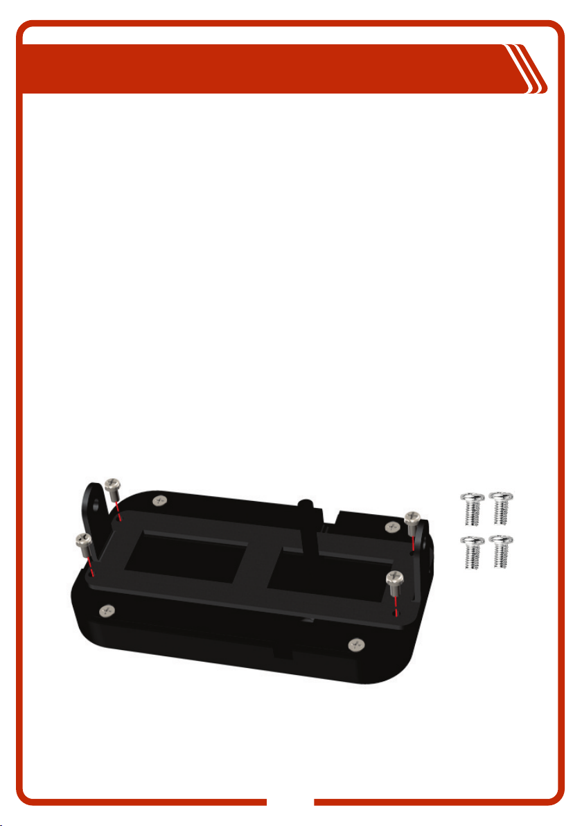
15. The Control Box may be mounted in any orientation but must be mounted onto a
flat, solid surface using M6 screws or bolts. Failure to adequately mount the unit,
such as using adhesives to mount the unit will result in unreliable operation of
system. It is the installer’s responsibility to ensure their installation complies with
any applicable legal and regulatory requirements.
16. The Switch Panel App and has not been tested on all smartphones available on
the market so is not guaranteed to work on all devices. However, the app should
work on most phones with Bluetooth® 4.0 (or later) running IOS 11. 1 (or later) or
Android 7.0 (or later).

3
WHAT’S INCLUDED
Control Box
Control Harness & Power Cables
Mounting Brackets & Hardware Switch Labels
(50x Graphic Decals)
Switch Panel
Heavy Duty Circuit Breaker

4
PRODUCT FEATURES
• Control up to 8 circuits via Switch Panel or Bluetooth app.
• Programmable switch modes: Toggle, Momentary, Pulsed
• RGB colour changeable switch panel backlight
• Backlight dims automatically with brightness control setting
• Customizable Switch Panel with 50 individual graphic labels
• System voltage range: 12V - 24VDC
• Max. Input Current: 60 Amps
• Emergency Low Voltage Cut-Off (A dedicate Low Voltage Drop Out (LVD)
should still be used to ensure your battery system is properly protected)
• Includes all necessary installation wiring harnesses and hardware
• Spare fuses (6x) and fuse pulled located in control box
SPECIFICATIONS
Backlight Function
Switch Control Function
Operating Voltage Range
Power Handling
Maximum Current
Switch Panel Dimensions
Control Box Module Dimensions
Technology
Bluetooth
Toggle Mode - red indicator light
Momentary Mode - blue indicator light
Pulsed Mode - green indicator light
Adjustable dimmer function with RGB
LED colour settings
8-30V
720W (12V System) - 1440W (24V System)
60A
1mA (Low Ambient Light)
20mA (High Ambient Light)
190 x 114 x 35mm
IGBT
Yes
Standby Current
115 x 66 x 15mm

5
DIMENSIONS
3000mm (3M)
800mm
600mm
200mm

6
CONTROL BOX INSTALLATION
The Control Box can be mounted in a number of ways; including fixed mount
using the supplied bracket or flush mounted to any flat surface, using the
mounting points on the units base. When choosing the mounting location,
consider the following:
• Check Power Cables with reach supply battery and allow for unobstructed
path for cables and control harness.
• Area behind mounting surface should be checked carefully to ensure no
existing wiring or vehicle components will be damaged during the installation
process.
• Ideal surface thickness 3 - 6mm
Fixed Mount Bracket Option
• Choose the most suitable mounting origination for the bracket and Control
Box.
• Using the mounting bracket as guide, mark the mounting holes and drill with
7mm bit.
• Use supplied (4x) M6x16mm cross head bolt, washers and nuts to secure
bracket to surface then fix Control Box to bracket.

7
Using the Control Box as a guide, mark mounting holes and cable routing
cutouts. Drill holes with a 7mm bit and carefully cut the cable routing access
with a jigsaw.
Use supplied M6x16mm cross head bolts, washers and nuts to secure the
Control Box base to the surface.
Flush Mount Option

8
SWITCH PANEL MOUNTING
There are two different mounting bracket options provided for Switch Panel:
Adjustable mount bracket for customizing the panel angle or fixed mount
bracket for flush fitment to any flat surface.
When choosing the mounting location, consider the following:
• Check Control Harness is long enough to reach the desired location and
allow for an unobstructed path for harness.
• Area behind mounting surface should be checked carefully to ensure no
existing wiring or vehicle components will be damaged during the installation
process.
• Ideal surface thickness 3 - 6mm
After the installation of the Switch Panel and Control Box, proceed to the
wiring installation.
Adjustable Mount Bracket Option
1. Screw part of bracket to back of Switch Panel as shown with the (4x)
M3x6mm Cross Round Head screws.

9
2. Mount the other part of bracket to desired surface with M5 screws.
Choose the appropriate length screw to suit surface thickness.
NOTE: Check behind fitment area that not existing wiring will be damaged
M5*10 M5*18 M5*23
3. Using the supplied Allen key tool and (2x) M5 hex socket bolts, attach the
two parts of the adjustable bracket together.
4. Before fully tightening the bolts, find the desired angle for the switch panel.

10
Flush Mount Option
1. Choose the appropriate cable direction before fixing the flush mount bracket
to the switch panel. These include through wall or surface routing for the
cable direction.
2. Use the (2x) M3 x 6mm Cross Counter Sunk screws to fix the flush bracket
to the back of the switch panel as shown.

11
3. For through wall cable routing, use the template shown as a guide for cutting
the access hole for the switch panel connection cable.
NOTE: Check behind fitment area that not existing wiring will be damaged
before drilling or cutting surface.
4. Mount switch panel to the desired surface with the supplied M5 screws.
Choose the appropriate length screw to suit surface thickness.
M5*10
M5*18
M5*25

12
14
2 3
58
6 7
1
2
3
4
5
6
7
8
Connect the extension wire to the
Control Box connector and the
switch panel.
WIRING INSTALLATION
Caution: Before powering on the Switch Panel make sure all power cables are wired correctly as shown
and all connection are tightly secured. If the supplied power cables are not a suitable length for the
installation, you must increase the cable size accordingly to reduce any potential voltage drop. Always
install the circuit breaker close to the battery, using the shortest cable length possible.
Fuse Indicator Light
When the LED light is red, the fuse is blown.
Replace it with the back-up fuse found in the
lid of Control Box. If problem persist, contact
customers support.
Connect to 8 auxiliary LED lights or electrical devices
Output Connections
When connecting a load to the control panel, ensure the connected loads rating does not exceed the
connected outputs fuse rating
2
3
4
5
6
7
81
60A
Vehicle Battery
Head Lights
ACC
Car Cigarette
Adaptor
Small red positive wire is the system enable wire. The unit will
not operate without this connected to a positive source. If
connecting to a vehicle battery, it is recommended to connect
the small positive wire a switched IGN circuit.

13
14
2 3
58
6 7
2
3
4
5
6
7
81
60A
KALVD2AND KASMARTBG
RECOMMENDED
If connecting to an auxiliary battery or control device such as the KickAss Control Hub or Battery Box it is
recommended to connect the small positive wire to the output of an LVD to ensure the auxiliary battery is
not over discharged
CONNECTION OPTIONS

14
5A
20A
5A
20A
10A
30A
Circuit 1 Circuit 2 Circuit 3 Circuit 4
30A 30A 20A 20A
Circuit 5 Circuit 6 Circuit 7 Circuit 8
10A 10A 5A 5A
10A
30A
The Switch Panel control system has eight switched circuits, each has a
maximum current rating. The total operating amperage of the connected
accessories can not exceed 60 amps. You may have multiple electrical devices
or auxiliary LED lights connected that total more than 60 amps, but you can not
have them turned on at the same time. Otherwise, the control box will be
damaged. The switch panel comes configured with the following fuses:
SWITCH PANEL INDICATION
1 - Red/Green/Blue LED indicator LED lights up to show the circuit is powered on.
2 - Area for DIY placement of the selected switch labels.
3 - Position of the integrated dimmer sensor for backlight.
4 - Manual master on/off activation button, press it to power on or off all circuits.
5 - Red LED lights up when you press the manual master on/off activation button.
6 - Switch panel backlight is activated when master On/Off button is pressed.
Backlight colour is green by default.
4
6
5
1
2
3

15
Step 1: Press the ON/OFF button and any of the other switch buttons at the
same time once, then release your fingers. Backlight Setting Mode is now
entered.
Step 2: Press and hold Button No. 1 the backlight
colour will change gradually in an anti clockwise
direction, or press and hold Button 4 to change
colour in a clockwise direction. Release your
finger when the desired backlight colour is
selected. Press the ON/OFF button again once
to save the setting.
There are a total of 64 different colours of the backlight available. To resume
factory setting - green backlight, press the ON/OFF button and hold on for at
least 12 seconds, then release your finger. Press the ON/OFF button again to
save the setting.
14
Button No. 1 Button No. 4
ON/OFF
Button
BACKLIGHT COLOR & BRIGHTNESS
By default, the backlight is a green colour, the brightness of the backlight is
automatically dimmable according to the brightness variation of the surrounding
environment. The darker the surrounding is, the darker the backlight will be; the
brighter the surrounding is, the brighter the backlight will be.
To change the backlight colour, please check the steps below:

16
Step 1: Press On/Off
button to power on
Panel.
SWITCH MODE PROGRAMING
The switch panel has 8 circuits that can be programmed as either Toggle,
Momentary or Pulsed Mode. By default each switch circuit is set to Toggle
Mode. To enable or disable the three modes, please follow the steps below to
manually program the function modes.
Function of Switch Modes explanation:
Toggle Mode: Press the desired switch once to power on the connected device,
press the switch button again to power if off.
Momentary Mode: The connected device will be activated only when you press
the desired switch button, and when you release the button the device will be
off.
Pulsed "LED" Mode: When you press the desired switch, the connected LED
light will be activated and will continue to flash or strobe. Press the circuit again
to turn the LED off.
Step 2: Press the ON/OFF button twice very
quickly to enter the "Switch Mode Settings".
Press and release the switch circuit button you
wish to program until the desired mode is
selected. Then press the ON/OFF button again
to save the setting within 12 seconds.
Red indicator light
Toggle Mode
Blue indicator light
Momentary Mode
Green indicator light
Pulsed Mode
Switch Mode Settings: All indicator
LED's will flash simultaneously when
setting mode is entered.
Step 3: Test functionality of the switch circuit to confirm the mode setting. If you
are unsuccessful, power off the switch panel and repeat steps 1-2. Don't forget
to press the ON/OFF button to save the settings!
Step 4: Repeat steps 1-3 to change/set the mode for all 8 circuits.

17
SMART PHONE CONTROL AVAILABLE
For Apple Devices For Android Devices
Scan the QR code and download the App - Switch Panel. The App allows for
full control of the switch panel as well switch mode function programming.
Download the App user guide for details.

18
For warranty, please send inquires to
sales@kickassproducts.com
This device complies with part 15 of the FCC Rules. Operation is subject to the
following two conditions: (1) this device may not cause harmful interference, and (2)
this device must accept any interference received, including interference that may
cause undesired operation.
Note: This equipment has been tested and found to comply with the limits for a Class
B digital device, pursuant to part 15 of the FCC Rules. These limits are designed to
provide reasonable protection against harmful interference in a residential installation.
This equipment generates, uses, and can radiate radio frequency energy and, if not
installed and used in accordance with the instructions, may cause harmful
interference to radio communications. However, there is no guarantee that
interference will not occur in a particular installation.
If this equipment does cause harmful interference to radio or television reception,
which can be determined by turning the equipment off and on, the user is encouraged
to try to correct the interference by one or more of the following measures:
ŸReorient or relocate the receiving antenna.
ŸIncrease the separation between the equipment and receiver.
ŸConnect the equipment to an outlet on a circuit different from that to which the
receiver is connected.
ŸConsult the dealer or an experienced radio/TV technician for help.
Changes or modifications to this product not authorized by KickAss could void the
electromagnetic compatibility (EMC) and wireless compliance and negate your
authority to operate the product.
This product has demonstrated EMC compliance under conditions that included the
use of compliant peripheral devices and shielded cables between system
components. It is important that you use compliant peripheral devices and shielded
cables between system components to reduce the possibility of causing interference
to radios, television sets, and other electronic devices.
Exposure to radio frequency energy. The radiated output power of this device
meets the limits of FCC/IC radio frequency exposure limits. This device should be
operated with a minimum separation distance of 20 cm (8 inches) between the
equipment and a person’s body.
FCC COMPLIANCE STATEMENT
Table of contents
Popular Control Panel manuals by other brands

CAME
CAME IO-RS485 installation manual

Dimplex
Dimplex WPM EconPlus operating instructions

Global Fire Equipment
Global Fire Equipment ORION PLUS Installation & commissioning manual

CSI Controls
CSI Controls Fusion Installation and operation manual

Brightsky
Brightsky JB-QB-5Ei user manual

Mitsubishi Electric
Mitsubishi Electric E1041 installation manual