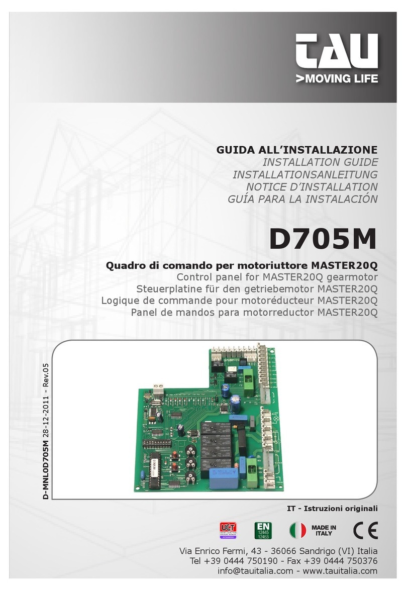
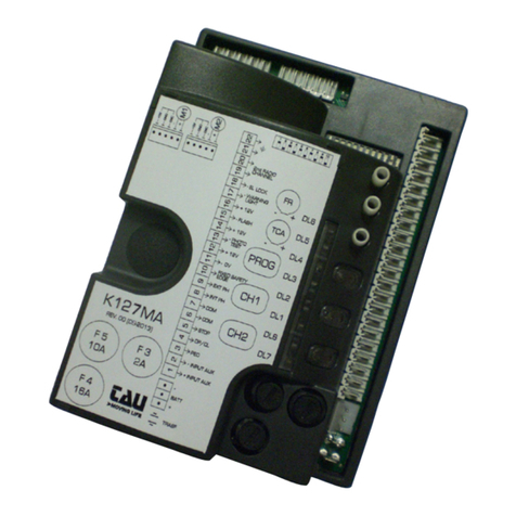
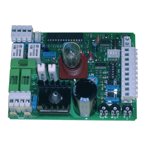
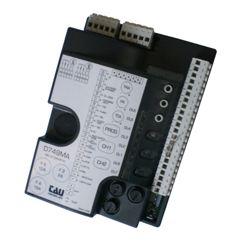
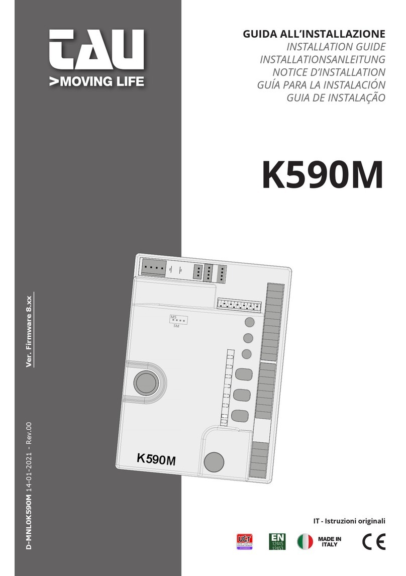
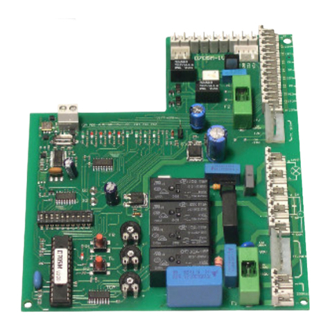
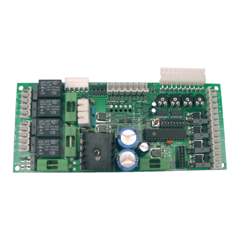
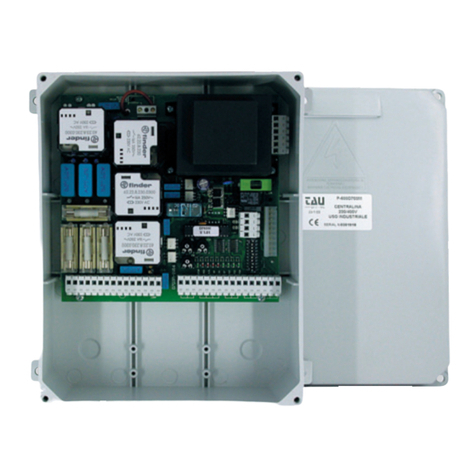
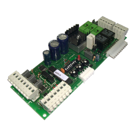
tau D760M User manual

1
D760M
GUIDA ALL’INSTALLAZIONE
INSTALLATION GUIDE
INSTALLATIONSANLEITUNG
NOTICE D’INSTALLATION
GUÍA PARA LA INSTALACIÓN
GUIA DE INSTALAÇÃO
D760M
Quadro di comando per due motori monofase 230V AC
Control panel for two single-phase motors 230V AC
Steuerplatine für zwei einphasige 230V AC Motoren
Logique de commande pour
deux moteurs monophasés 230V AC
Panel de mandos para dos motores monofásicos 230V AC
Placa electrónica para dois motores monofásicos 230V AC
Via Enrico Fermi, 43 - 36066 Sandrigo (VI) Italia
Tel +39 0444 750190 - Fax +39 0444 750376
info@tauitalia.com - www.tauitalia.com
IT - Istruzioni originali
D-MNL0D760M 14-02-2018 - Rev.11
300
230
124

2
D760M
SCHEMA CABLAGGIO D760M / D760M WIRING DIAGRAM / SCHALTPLAN DER D760M
I O
12
12
3 4 5 6 7 8 9 10
3 4 5 6 7 8 9 10
11 12 13 14 15 16 17 18 25 26 2722 23 2419 20 21
11 12 13 14 15 16 17 18 25 26 2722 23 2419 20 21
F1
P1 P2
J1
F2
28
28 29
29
R.ANTA FR. M1 CH.AUTO
FR. M2
DL7
J1
DL7

3
D760M
SCHÉMA CÂBLAGE D760M / ESQUEMA DEL CABLEADO D760M / ESQUEMA ELÉCTRICO D760M
O/C =Open/Close
Ped = Pedestrian
Cap = Capacitor
TX = Transmitter
RX = Receiver
E.L. = Electric lock
M = Motor
SPIA
AP2
230Vac
M3
1
23 4 5 6 7 8 9 10
CH1COM1 AP1CH2COM2 FOTI
11 12 13 14 15 16
COMAP/CH PED STOP CF COM
17 18
FOTE 24FOT
25
0VAC
26 2722 23 2419 20 21
24VAC
LAMP M2 M1
E.SERR 2 CH
230 Vac
Power supply
Flashing
light
230 Vac
max. 50W
Close
Common
Open
Close
Common
Open
Cap Cap
TX
1 2
RX
12345
Common
Sensitive edge
Internal photocell (N.C)
External photocell (N.C.)
Common
O/C
Ped
Stop
E.L.
12V 15W
2nd radio
channel
Gate open
warning light
max. 3W
Ext.
photoc.
Int.
photoc.
RX
12345
TX
1 2
Antenna

13
D760M
MANUFACTURER’S DECLARATION OF INCORPORATION
(in accordance with European Directive 2006/42/EC App. II.B)
Manufacturer: TAU S.r.l.
Address: Via E. Fermi, 43
36066 Sandrigo (Vi)
ITALY
Declares under its sole responsibility, that the product: Electronic control unit
designed for automatic movement of: Swing Gates
for use in a: Residential / Communities
complete with: Radioreceiver
Model: D760M
Type: D760M
Serial number: see silver label
Control panel for two single-phase motors
230V AC
Has been produced for incorporation on an access point (swing gate) of for assembly with other devices used to
Also declares
- 2014/35/EU Low Voltage Directive
- 2014/30/EU Electromagnetic Compatibility Directive
and, where required, with the Directive:
- 2014/53/EU Radio equipment and telecommunications terminal equipment
Also declares that it is not permitted to start up the machine until the machine in which it is incorporated or of
pertinent to the quasi-machinery.
Legal Representative
_________________________________________
Loris Virgilio Danieli
Name and address of person authorised to draw up all pertinent technical documentation:
Loris Virgilio Danieli - via E. Fermi, 43 - 36066 Sandrigo (Vi) Italy
ENGLISH

14
D760M
WARNINGS
D760M and may therefore not be used for different products!
Important information:
Disconnect the panel from the power supply before opening it.
The D760M control unit has been designed to control an electromechanical gear motor for automating
gates and doors of all kinds.
When designing its products, TAU observes all applicable standards (please see the attached decla-
ration of conformity) but it is of paramount importance that installers strictly observe the same stand-
and doors” category may not install systems under any circumstances.
Whoever ignores such standards shall be held responsible for any damage caused by the
system!
Do not install the unit before you have read all the instructions.
INSTALLATION
Before proceeding, make sure the mechanical components work correctly. Also check that the
gear motor assembly has been installed according to the instructions. Then make sure that
the power consumption of the gear motor is not greater than 3A (otherwise the control panel
may not work properly).
-
Note: it is compulsory to earth the system and to observe the safety regulations that are in
force in each country.
-
ENGLISH

15
D760M
ENGLISH
CONTROL CARD FOR TWO SINGLE-PHASE MOTORS 230V AC
-
ATTENTION:
- do not use single cables (with one single wire), ex. telephone cables, in order to avoid
breakdowns of the line and false contacts;
- do not re-use old pre-existing cables.
TESTING
When all connections have been made:
safeties
-
nostics Led”)
TECHNICAL CHARACTERISTICS
600 W ca.
F 3,15 A
Input voltage of motor circuits
Input voltage of auxiliary circuits
F 500 mA
Logic circuit input voltage
Working temperature
IP43
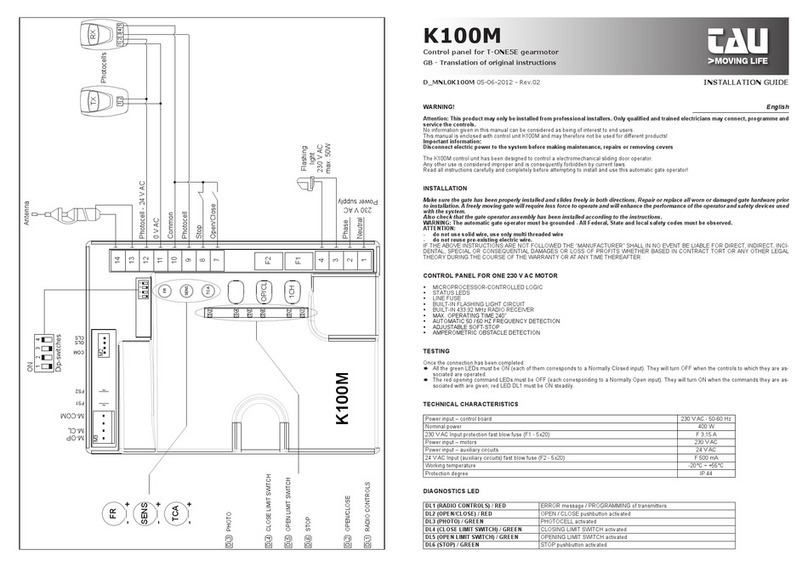
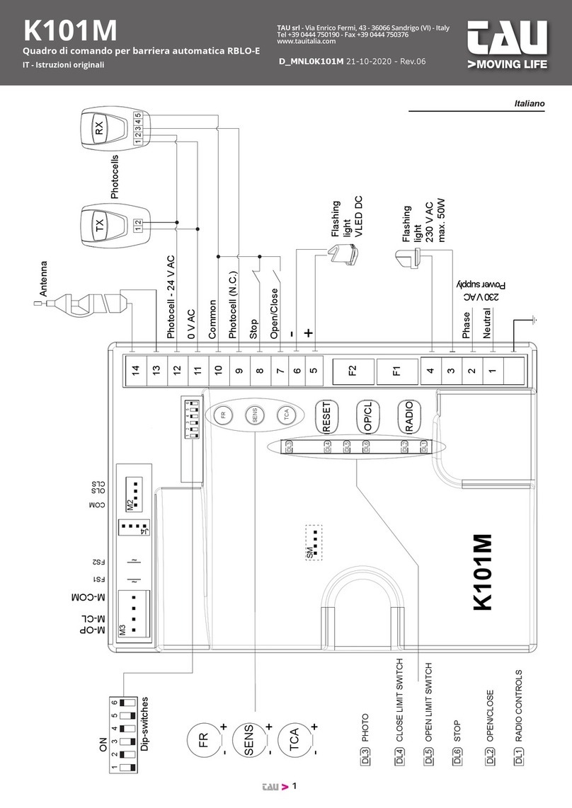
TERMINAL BOARD CONNECTIONS
Key:
-
Terminals Function Description
1 - 2 POWER
SUPPLY
3 - 4 FLASHING
LIGHT
modulated for direct use. Flashing frequency is double
5 - 6 - 7 MOTOR M1
Notice: connect the capacitor between terminals 5 and 7;

16
D760M
8 - 9 - 10 MOTOR M2
MOTOR M2 power output, 230 Vac, max. 300 W.
8=CLOSE, 9=COMMON., 10=OPEN.
Notice:
11 - 12 OPEN/CLOSE OPEN/CLOSE button input (contact normally open); for operating
information see dip-switches 2 and 3 functions. (COMMON=11);
11 - 13 PEDESTRIAN
N.O. PEDESTRIAN button contact input – commands total opening
and closing of motor 1 – governed by dip-switches 2 and 3.
(COMMON=11);
11 - 14 STOP
STOP button input (normally closed contact); this stops the automatic
system. At the next command, the opposite operation to the previous
one is performed (COMMON=9). Bridge the connectors if not used;
15 - 18 SENSITIVE
EDGE
SENSITIVE EDGE input (potential free contact N.C., dip 10 OFF) or
It works during both the opening and closing phases, causing the
temporary stop of the automation and its partial movement reversal
for 20cm, therefore freeing any obstacle (18=COMMON) Note: short-
circuit if not used.
16 - 18 INTERNAL
PHOTOCELLS
PHOTOCELL OR SAFETY DEVICE input INSIDE the automation
(Normally Closed contact); COMMON=18.
When these devices trigger during the opening phase, they tem-
porarily stop the automation until the obstacle has been removed;
during the closing phase they stop the automation and then totally
open it again. Bridge the connectors if not used.
17 - 18 EXTERNAL
PHOTOCELLS
PHOTOCELL OR SAFETY DEVICE input OUTSIDE the automation
(Normally Closed contact); COMMON=18.
Then these devices trigger during the closing phase, they stop the auto-
mation and then totally open it again. Bridge the connectors if not used.
-
19 - 20 ELECTRIC LOCK ELECTRIC LOCK power output 12 Vac max. 15 W;
21 - 22 2nd RADIO CH
2nd RADIO CHANNEL output; the output mode can be selected
through Dip Switches 7 - 8;
23 - 24 GATE OPEN
WARNING LIGHT
GATE OPEN WARNING LIGHT output; 24 V ac, max 3W; the light
entire opening and closing manoeuvre and remains on if the gate is
open and off when the gate has closed;
25 - 27 PHOTOCELL TX
24 Vac external transmitting photocell power supply output for safe-
ty device control (connect the external TX photocell only) max. of 2
photocell transmitters;
26 - 27 AUX 24Vac output, 10W for the power supply of photocells, external re-
ceivers, etc.
28 - 29 AERIAL AERIAL input (EARTH=28, SIGNAL=29);
ENGLISH

17
D760M
LOGIC ADJUSTMENTS
TRIMMER
R. ANTA
second motor delay adjustment: during closing cycle from approx. 0 to 30 sec. (on top
of the time that the card calculates automatically during the SETUP procedure)during
opening from approx. 0 to 6 sec (on top of the time that the card calculates automati-
cally during the SETUP procedure).
FR. M1
-
FR. M2
-
CH.AUTO Automatic closing time adjustment from
Notice: turn the TRIMMER clockwise to increase adjustments; turn it anticlockwise to
decrease.
PROGRAMMING INSTRUCTIONS (SETUP)
DOUBLE SWING GATE - DIP SWITCH # 4 in ON (Soft-Stop function enabled):
-
-
SINGLE SWING GATE - DIP SWITCH # 4 in ON ( Soft-Stop function enabled):
GATE 2 WINGS - DIP SWITCH # 4 in OFF (Soft-Stop function disabled):
ENGLISH

18
D760M
-
-
GATE 1 WINGS - DIP SWITCH # 4 in OFF (Soft-Stop function disabled):
Notice:
- during the SETUP procedure the safety devices are disabled.
- STOP input will stop the programming at any time. The programming mode remains active
and can be re-started from point 1
- while DL7 blinks, press and hold down for at least 5 seconds P1 and P2 buttons to kill exit
programming mode
- set a working time slightly longer than necessary (a couple of seconds) to allow complete
opening/closing of the leaves.
DIP SWITCH
1AUTOMATIC
CLOSING
On
Off
22 / 4 STROKE
On
-
3
Off in the same conditions, the same command sequence causes the
3NO REVERSE On NO RE-
VERSE)
Off
4DECELERATION On the deceleration function is on -
TIONS”)
Off
5PRE-FLASHING On
Off
6FOTOTEST
On
Off
ENGLISH

19
D760M
7MAN MODE On
Off Normal function
WARNING: with dip 7 ON the input OPEN / CLOSE (terminals 11-12) switches OPEN, the
PEDESTRIAN input (terminals 11-13) switches CLOSE.
In MAN mode, it is not necessary to run the race setup, and the dip-switches 1, 2, 3 and
4 are not used.
82nd RADIO CH
On
is activated and remains activated until the next pressure.
Off
9OPENING
RAM BLOW
On
of the electric lock (to be used only in the presence of an electric
Off
10 SENSITIVE EDGE
SELECTION
On
Off
Note: if not used, keep the DIP in the OFF position.
JUMPER J1
closes automatically after 5 seconds.
IMPORTANT:
ensure the proper operation of the board.
-
433.92 MHz BUILT-IN RADIO RECEIVER
The radio receiver can learn up to a maximum of 30SLIM-RP, T-
4RP
4_ LED DL7 turns on again to indicate that the code has been memorised (if this does not happen,
5_ to memorise codes to other radio control devices, repeat the procedure from point 1 up to a maxi-
mum of 30
Notice: if the maximum number of radio control devices (30
rapidly for about 3 seconds without memorising the code.
ENGLISH

20
D760M
-
ming buttons.
-
-
4_ LED DL7 turns off for approx. 3 seconds and then remains steady to indicate that the code has
DIAGNOSTICS LED
DL1 - Red
DL2 - Red PEDESTRIAN button red LED signal
DL3 - Green STOP button green LED signal
DL4 - Green
DL5 - Green
DL6 - Green
DL7 - Red and ERRORS red LED signal
Regular operation
Photo-cell Test Error
Missing Programming Error
Programming Mode Active
MALFUNCTIONS: POSSIBLE CAUSES AND SOLUTION
The automation does not start
The radio control has very little range
The gate opens the wrong way
GUARANTEE: GENERAL CONDITIONS
sales document, receipt or invoice).
-
ENGLISH

21
D760M
manship or materials.
for travelling expenses and labour costs.
The guarantee does not cover the following cases:
provided by the company inside the product pack.
improper repairs, incorrect installation, or other reasons that do not depend on TAU.
-
ing to the instructions provided by the company inside the product pack.
The repair or replacement of pieces under guarantee does not extend the guarantee period.
ENGLISH
Other manuals for D760M
1
Table of contents
Other tau Control Panel manuals
Popular Control Panel manuals by other brands
Honeywell Home
Honeywell Home TrueZONE HZ322 Professional installation guide
Zonefirst
Zonefirst BPE Installation and operating instructions
DSC
DSC Power Series PC1616 quick guide

CAME
CAME TS4.3 user manual
Autonics
Autonics LP-A Series product manual
PEDROLLO
PEDROLLO EVOLUTION Series operating instructions
