Heath Company Heathkit AG-7 Guide

G. Tannenbaum
Electronic Service Data
P.O. Box 386/Ambler PA 19002
Phone 215 657 0106 Fax 215 657 0520
Web Page www.agtannenbaum.com
EA TH KIT
MODEL AG-
AUDIO GENERATOR

G A
G YO
-III!-~
Audio Generator
.. Model AG-
THE HEATH COMPANY
BENTON HARBOR, MICH.
PRICE $1.
- n
~--- -- - ---- __
d__--__- --
~------ -----
,"""""""""""""""""""""" U
"""""""""""""""" "'" ""'"
I NFORMA lrON FOR KIT
,,',,""""""""""""""""""""""""""""""""""""""""""
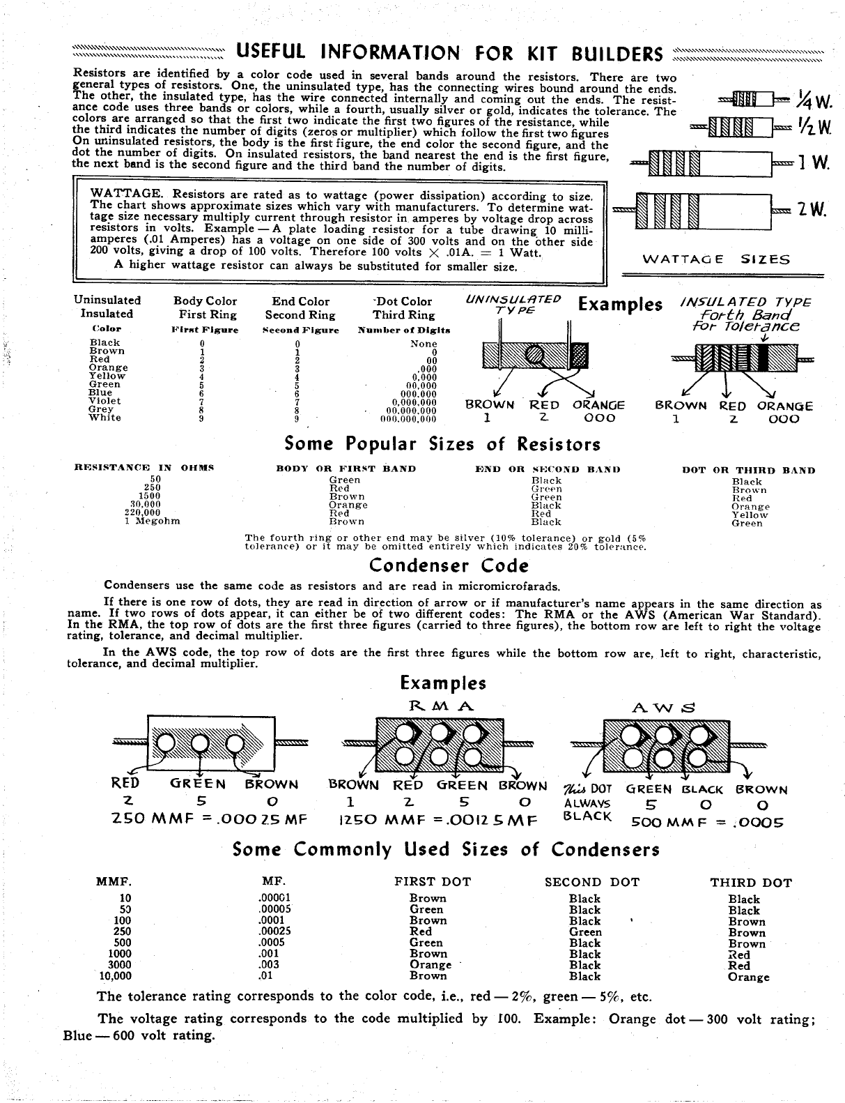
Resistors are identified by a color code used in several bands around the resistors. There are two
general types of resistors. One, the uninsulated type, has the connecting wires bound around the ends.
The other, the insulated type, has the wire connected internally and coming out the ends. The resist-
ance code uses three bands or colors, while a fourth, usually silver or gold, indicates the tolerance. The
colors are arranged so that the first two indicate the first two figures of the resistance, while
the third indicates the number of digits (zeros or multiplier) which follow the first two figures
On w1insulated resistors, the body is the first figure, the end color the second figure, and the
dot the number of digits. On insulated resistors, the band nearest the end is the first figure
the next band is the second figure and the third band the number of digits.
WATTAGE. Resistors are rated as to wattage (power dissipation) according to size.
The chart shows approximate sizes which vary with manufacturers. To determine wat-
tage size necessary multiply current through resistor in, amperes by voltage drop across
resistors in volts. Example - A plate loading resistor for a tube drawing 10 milli-
amperes (.01 Amperes) has a voltage on one side of 300 volts and on the other side
200 volts, giving a drop of 100 volts. Therefore 100 volts X .01A. = 1 Watt.
A higher wattage resistor can always be substituted for smaller size.
-fDI
=1m
~.~,
V2.W
1 W.
2W.
WATTAG E SIZES
Un insulated Body Color End Color Dot Color UNINSUL-RTED Examples INSULATED TYPE
Insulated First Ring Second Ring Third Ring TYPE; Forth. Band
-Fo,.. To/etance
Color lrKt Figure "eeond Figure Number of Digits
Black None
Brown
Red
Orange 000
Yellow 000
Green 00.000
Blue 000.000
Violet 000.000 BROWN RED ORANGE BROWN RED ORANCJE
Grey 00.000.000 000 000
White 000.000,000
Some Popular Si zes Resistors
RESISTANCE IN
250
1500
30,000
220 000
1 Megohm
OHMS BODY OR FIRST
Green
Red
Brown
Orange
Red
Brown
BANI) DOT OR THIRD
Black
Brown
Hed
Orange
Yellow
Green
BilND
BAND F)ND OR ';COND
Black
Gre.'n
Grf'en
Black
Hed
Black
The fourth ring or other end may be silver (10% tolerance) or gold (5%
tolerance) or it may be omitted entirely which indicates 20% toho rance.
Condenser Code
Condensers use the same code as resistors and are read in micromicrofarads.
If there is one row of dots, they are read in direction of arrow or if manufacturer s name appears in the same direction as
name. If two rows of dots appear, it can either be of two different codes: The RMA or the A WS (American War Standard).
In the RMA, the top row of dots are the first three figures (carried to three figures), the bottom row are left to right the voltage
rating, tolerance, and decimal multiplier.
In the A WS code, the top row of dots are the first three figures while the bottom row are, left to right, characteristic
tolerance, and decimal multiplier. Examples
RMA
=;IJft=
'BROWN RED GREEN BROWN
12~O MMF = OOI25MF
AVVS
RED GREEN BROWN
"2.
ZSO MMF
=' .
0002.5 MF
1t.:.& DOT
A LWAVS
BLACK
G~EEN BLACK BROWN
500 MM F = ,0005
Some Commonly Used Si zes of Condensers
MMF. MF. FIRST DOT
10 .00001 Brown
5:) .00005 Green
100 .0001 Brown
250 .00025 Red
500 .0005 Green
1000 .001 Brown
3000 .003 Orange
000 .01 Brown
The tolerance rating corresponds to the color code, i.e.,
The voltage rating corresponds to the code multiplied
Blue - 600 volt rating.
SECOND DOT
Black
Black
Black
Green
Black
Black
Black
Black
red - 2%, green - 5%, etc.
by 100. Example: Orange
THIRD DOT
Black
Black
Brown
Brown
Brown
Red
Red
Orange
dot - 300 volt rating;
'"'
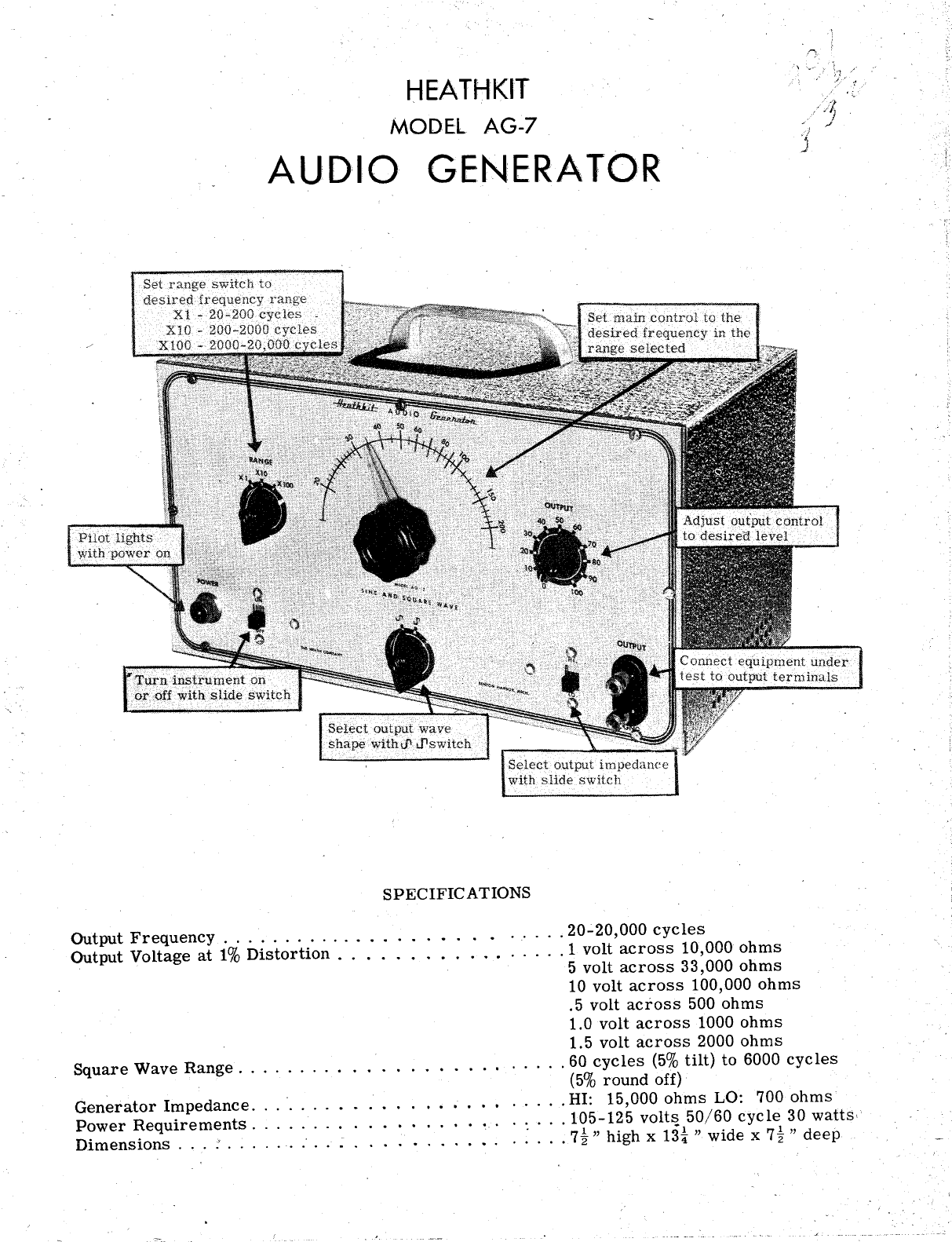
HEATHKIT
MODEL AG-
AUD;IO GENERA TOiR
SPECIFIC A TIONS
OutputFrequency..............
Output Voltage at 1% Distortion.
. . . . . . .....
20- 000 cycles
. . . . . . . .
1 volt across 10 000 ohms
5 volt across 33 000 ohms
10 volt across 100 000 ohms
5 volt across 500 ohms
1.0 volt across 1000 ohms
1.5 volt across 2000 ohms
Square Wave Range. . .
. . . . . . . . . . . . . . . . . ' . . . .
60 cycles (5% tilt) to 6000 cycles
(5% round off)
Generator Impedance. .
.. . . . . . . . . . . . . . . . .. . . .
HI: 15 000 ohms LO: 700 ohms
Power Requirements. . . . . . .
. . . . . . . . . .. . . . . .
105-125 volts 50/60 cycle 30 watts;
Dimensions..............
..... . :...
7t" highx13i" widex7t" deep
ASSEMBLY OF THE HEATHKIT
MODEL AG-
AUDIO ,GENERA TOR
The Heathkit Audia Generatar will .offer excellent .operating characteristics if praperly can-
structed. Ta insure many years .of traublefree service, the assembly and wiring sh.ould be
undertaken withaut hurrying. Take yaur time ta da a gaad jab:
This manual is intended ta facilitate pr.opercanstructi.on. THEREFORE READ THE MANUAL
COMPLETELY THROUGH BEFORE PROCEEDING WITH THE CONSTRUCTION. In this man-
ner y.ou will become familiar with the c.ontents .of the manuq.l. Then during canstructian yau can
readily refer back to specific paragraphs and pictarials.
UNPACK THE KIT CAREFULLY AND CHECK EACH PART, AGAINST THE PARTS LIST. -In
so d.omg y.ou. will became acquainted with the parts. If a sh.ortage is, found, please natify us
promptly, and attach the inspectian slip ta yaur claim. Screws, nuts and washers are caunted
mechanically, and if a few are missing, please secure them lacally. Use the charts an the inside
cavers .of this manual to identify the parts.
Read the nate an saldering an the inside .of the back caver. Make a gaod mechanical cannectian
with clean metal ta clean metal. Use .only the best quality Rasin Care Radio type salder . Paste
fluxes .or acids are difficult ta remave and even minute quantities left behind will cambine with
maisture fram the air ta farm a carrasive praduct. This carrasive praduct is generally a gaad
canductar and may cause shart circuits between switch contacts .or tube sacket lugs. Mter
weeks .or manths the carrasian may result in untimely failure .of the instrument.
NOTE: ALL GUARANTEES ARE VOIDED AND WE WILL NOT REPAffi OR SERVI9E
INSTRUMENTS IN WHICH ACID CORE SOLDER OR PASTE FLUXES ARE USED.
(When in daubt abaut s.older, it is rec.ommended that a new rall plainly marked "Rasin
Care Radia Salder" be purchased.
Resistars and cantrals generally have a talerance rating .of plus .or minus 20%, unless .otherwise
stated. Therefare a 10 000 .ohm resistar may test anywhere fram 8 000 ta 12 000 .ohms. The
talerance an candensers is generally even greater. Limits .of minus 50% and plus 100%are cam-
man for paper tubular types. This Heathkit is designed taaccommadate such variatians.
Small changes in parts may be made by the Heath Campany. All parts supplied will work just
as well as the part far which it was substituted. By reading thecalar code an resistars, for
instance, it will be readily understaad that a value .of 3.9 megahms is a substitute far the spec-
ified 3. 3 megahms, .or a resistar caded 8200 .ohms is a substitute far the s-pecified OQO .ohms
pravided the specified values are nat supplied. Such changes will .only be made if the specified
parts are unabtainable at the time, and are .only made ta insure a minimum delay in filling your
.order.
The tube socket pins are numbered fram 1 ta 8, starting at the keyway' and reading clackwise
when viewed fram the battam.
Fallaw the pictarial diagram for the best placement .of the wiring. The "lead dress" .or place-
ment .of the wires is quite impartant in this instrument as incarrect placement may result in
higher distartian leve Is.
Page 1
--~- --.._---- - ---- ---------- --,--------~ ----
STEP BY STEP ASSEMBLY
Use of bare wire where indicated will facilitate wiring, but insulated wire may be used. Use
spaghetti (insulated sleeving) over bare wires on condensers and resistors. where necessary to
prevent the leads from accidentally touching other bare wires or metal parts.
Use lockwashers under all 6-32 and 8-32 nuts and between all controls and panel.
Read each paragraph fully through before proceeding.
Check off each step in the space provided (Y) as it is completed.
(S) means solder the connection (NS) means do not solder yet
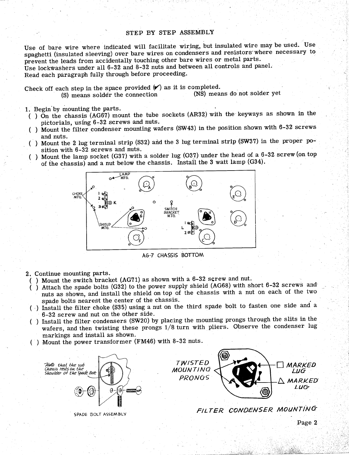
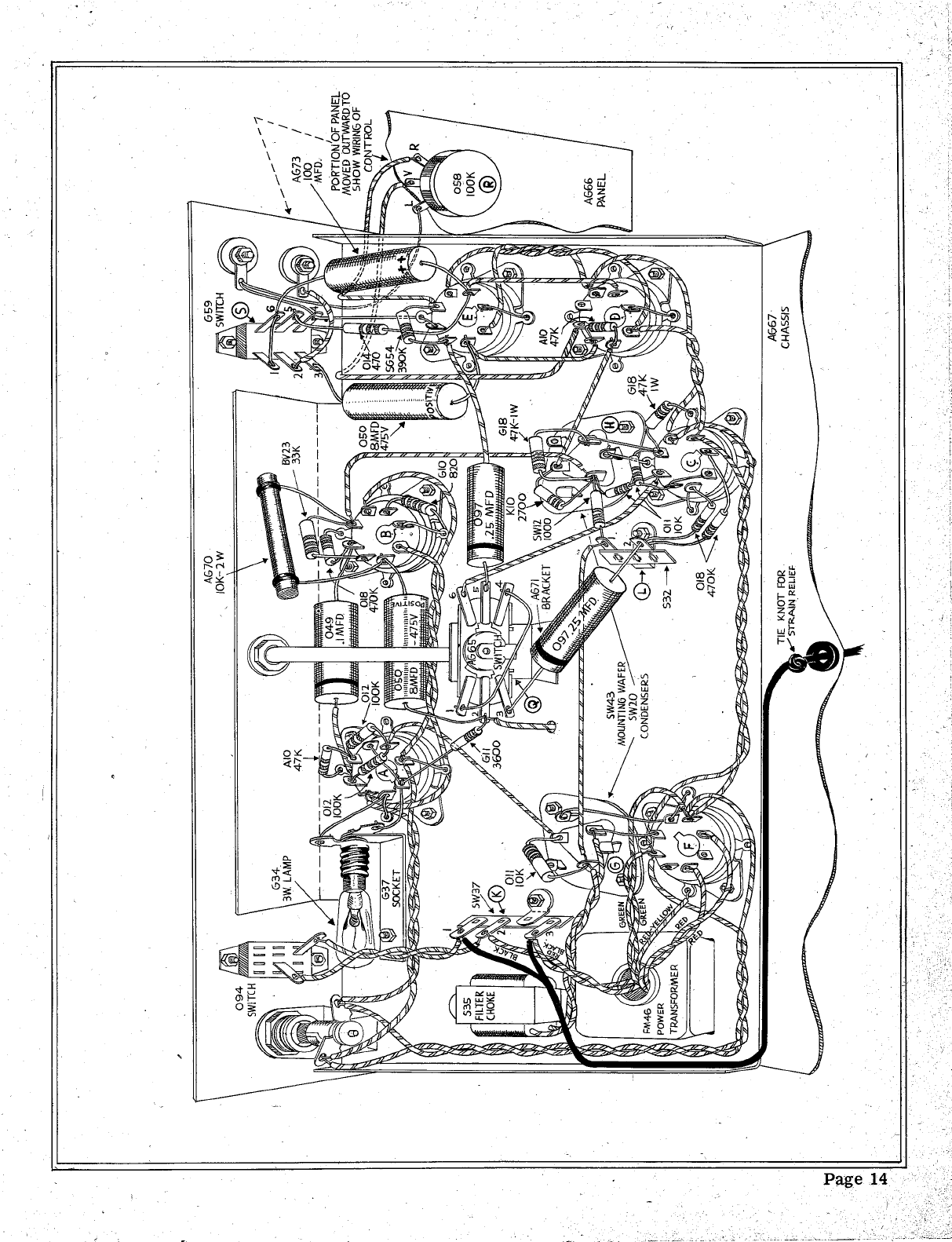
1. Begin. by mounting the parts.
( ) On the chassis (AG67) mount the tube sockets (AR32) with the' keyways as shown in the
piCtorials, using 6-32 screws and nuts.
( ) Mount the filter condenser mounting wafers (SW43) in the position shown with 6-32 screws
and nuts.
( ) Mount the 2 lug terminal strip (S32) aiid the 3 lug terminal strip ($W37) in the proper po-
sition with 6-32 screws and nuts.
( ) Mount the lamp socket (G37) with a solder lug (037) under the head of a 6-32 screw (on top
of the chassis) and a nut below the chassis. Install the 3 watt lamp (G34).
CHOKE
MTG.
LAMP
"---MT~- 0'\,
\'"
MTh
(3)
SWitCH
BRACKET
MT6. .
'1k
. \~
(E)
AG-7 CHASSIS BOTTOM
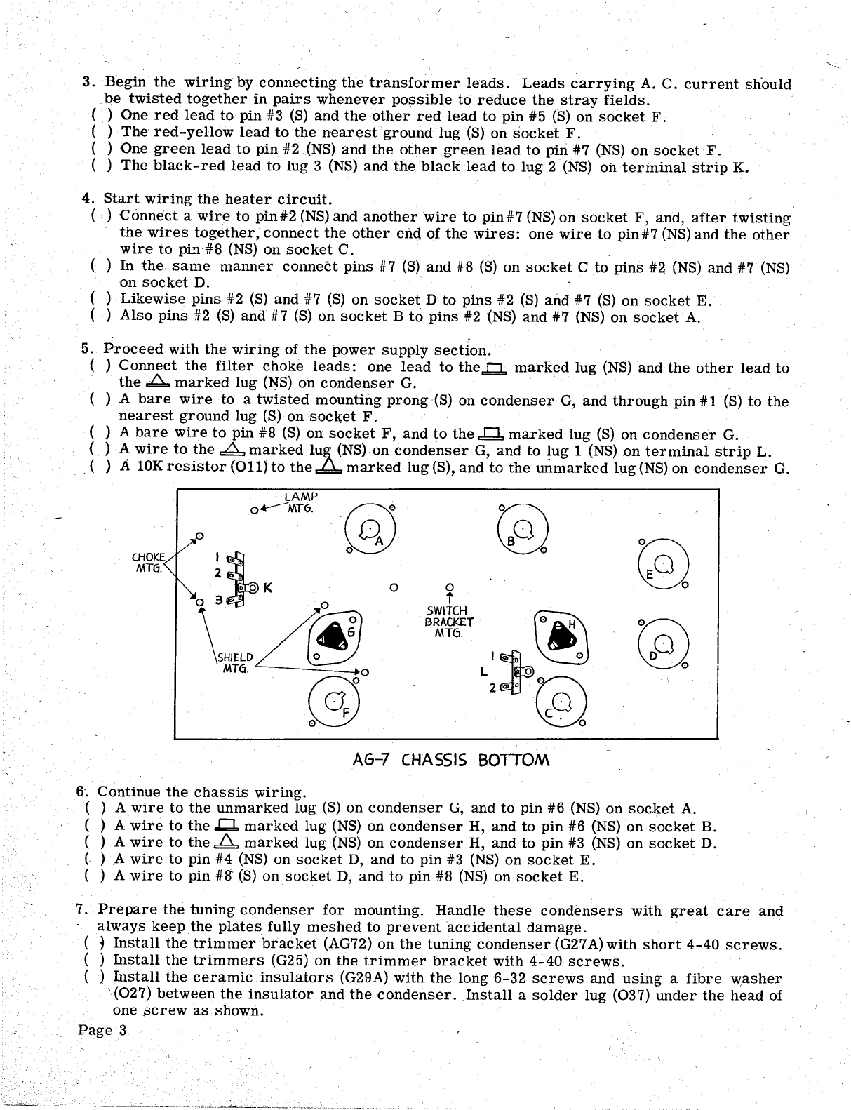
2, Continue mounting parts.
( ) Mount the switch bracket (AG71) as shown with a 6-32 screw and nut.
( ) Attach the spade bolts (G32) to the power supply shield (AG68) with short 6-32 screws and-
nuts as shown, and install the shield on top of the chassis with a nut on each of the two
spade bolts nearest the center of the chassis.
(.) Install the filter choke (S35) using a nut on the third spade bolt to fasten one side and' a
32 screw and nut on the other side.
) Install the filter condensers (SW20) by placing the mounting prongs through the slits in the
wafers, and then twisting these prongs 1/8 turn with pliers. Observe the condenser lug
markings and install as shown.
( ) Mount the power transformer (FM46) with 8-32 nuts.
/tel8 that the sub
Cha55is tests OK tke
5houldet 01 tlee ~e Bolt MARKED
LLJO
MARKED"
LUG-
TWISTED
MOUNTINO
PRONuC;
(GJ
SPADE BOLT ASSEMBLY FIL TER CONDENSER MOLlNTlNa
'--
3. Begin' the wiring by connecting the transformer leads. Leads carrying A. C. current should
be twisted together in pairs whenever possible to reduce the stray fields.
( ) One red lead to pin #3 (S) and the other red lead to pin #5 (S) on socket F.
( ) The red-yellow lead to the nearest ground lug (S) on socket F.
( ) One green lead to pin #2, (NS) and the other green lead to pin #7 (NS) on socket F.
( ) The black-red lead to lug 3 (NS) and the black lead to lug 2 (NS) Oh terminal strip K.
4. Start wiring the heater circuit.
( ) Connect a wire to pin#2 (NS) and another wire to pin#7 (NS) on socket F, and, after twisting
the wires together, connect the other end of the wires: one wire to pin #7 (NS) and the other
wire to pi!1#8 (NS) on socket C.
( ) In the same manner connect pins #7 (S) and #8 (S) on socket C to pins #2 (NS) and #7 (NS)
on socket D.
( ) Likewise pins #2 (S) and #7 (S) on socket D to pins #2 (S) and #7 (S) on socket E.
( ) Also pins #2 (S)and #7 (S) on socket B to pins #2 (NS) and #7 (NS) on socket A.
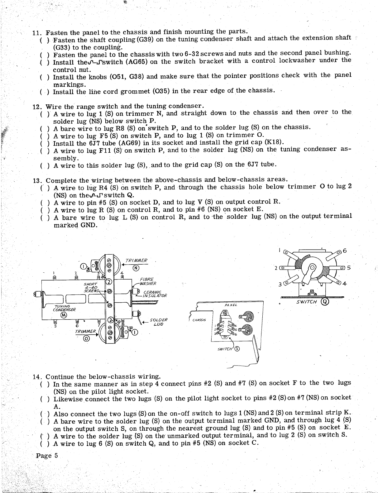
5. Proceed with the wiring of the power supply section.
( ) Connect the filter choke leads: one lead to the..!::!., marked lug (NS) and the other lead to
the marked lug (NS) on condenser G.
( ) A bare wire to a twisted mounting prong(S) on condenser G, and through pin #1 (S) to the
nearest ground lug (S) on socket F.
( ) A bare wire to pin #8 (S) on socket F, and to the..bJ. marked lug (S) on condenser G.
( ) A wire to the marked lu~ (NS) on condenser G, and to lug 1 (NS) on terminal strip L.
. . ( )
A 10K resistor (011) to the marked lug (S), and to the unmarked lug (NS) on condenser G.
LAMP
o~MT6-
CHOKE
MTG. (35
2 ..
\~f~D
swITCH
BRACKET IilIJtt.!
MT6-
G2)
. 0
AG-7 CHASSIS BOTTOM
. Continue the chassis wiring.
( ) A wire to the unmarked lug (S) on condenser G, and to pin #6 (NS) on socket A.
( ) A wire to the .bJ. marked lug (NS) on condenser H, and to pin #6 (NS) on socket B.
( ) A wire to the.ld. marked lug (NS) on condenser H, and to pin #3 (NS) on socket D.
( ) A wire to pin #4 (NS) on socket D, and to pin #3 (NS) on socket E.
( ) A wire to pin #ff (S) on socket D, and to pin #8 (NS) on socket E.
7. Prepare the tuning condenser for mounting. Handle these condensers with great care and
always keep the plates fully meshed to prevent accidental damage.
( ~ Install the trimmer-bracket (AG72) on the tuning condenser (G27 A) with short 4-40 screws.
( ) Install the trimmers (G25) on the trimmer bracket with 4- 40 screws.
( ) Install the ceramic insulators (G29A) with the long 6-32 screws and using a fibre v.zasher
(027) between the insulator and the condenser. Install a solder lug (037) under the head of
one screw as shown.
Page 3

TRIMMER
CERAMIC
"-INSULATOR
TRIMMER
(Q)
8. Wire the tuning condenser assembly and mount it on the chassis.
( ) A bare wire to lug 3 (S) on condenser M, and through lug 1 (NS) on trimmer N, to
on condenser M.
( ) A wire to lug 2 (S)on trimmer N, and to the solder lug (NS).
( ) A wire to lug 5 (S), and to lug 8 (NS) on condenser M.
( ,
) A bare wire to lug 8 (S) on condenser M, and to lug 1 (NS) on trimmer O.
( ) A bare wire to lug 2 (S) on trimmer 0, and to the solder lug (NS).
( ) Mount the assembly on the chassis with 8-32 screws.
lug 2 (S)
9. Prepare the range switch (S34) (switchP).
( ) A 10 meg precision resistor (AG63) between lug F2 (S) and lug R2 (NS).
( ) A 1 meg precision resistor (AG62) between lug F3 (S) and lug R3 (NS).
( ) A lOOK precision resistc.r (AG64) between lug F4. (S) and lug R4 (NS).
( ) A bare wire connecting lugs R2 (S), R3 (S) and R4 (NS).
( ) A 10 meg precision resistor (AG63) between lug F8 (S) and lug R8 (NS).
( ) A 1 meg precision resistor (AG62) between lug F9 (S) and lug R9 (NS).
( ) A lOOK pr~cision resistor (AG64) between lug F10 (S) and lug RI0 (NS).
( ) A bare wire connecting lugs RI0 (S), R9 (S) and R8 (NS).
R2
~::JER
TRL
'"
WR5HER
PANEL (o/!LOCK
,;;nSHER..
SWITCH P
PILOT LIGHT ASSEMBL Y
10. Install the parts on the panel.
( ) Install the first panel bushing (G30) in the center with a control lockwasher and a control
nut on the back of the panel.
( ) Mount the pilot light assembly (040, 041, 042, 052) and install the pilot lamp (039). ! ,
( ) Install the on-off slide switch (094) as shown with 6-32 screws and nuts.
( ) Install the HI- LO slide switch (G59) with 6-32 screws and nuts.
( ) Install the output terminal assembly (ffi31, ffi32, ffi33 , ffi34, IB36, ffi37 , ffi38 and 0109'). -
( ) Install the lOOK output control (058) with a controllockwasher between control and panel
and a nickel washer between the panel and the control nut.
( ) Install the range switch assembly in the same manner with the flat on the shaft towards the
. bottom edge of the panel. \ Page 4
Ii!!
11. Fasten the panel to the chassis and finish mounting the parts.
( ) Fasten the shaft coupling (G39) on the tuning condenser shaft and attach the extension shaft
(G33) to the coupling.
( ) Fasten the panel to the chassis with two 6-32 screws and nuts and the second panel bushing.
( ) Install thed'-J'switch (AG65) on the switch bracket with a control lockwasher under the
control nut.
( ) Install the knobs (0.51, G38) and make sure that the pointer positions check with the panel
markings.
( ) Install the line cord grommet (0.35) in the rear edge of the chassis.
12. Wire the range switch and the tuning condenser.
( ) A wire to lug 1 (8) on trimmer N, and .straight down to the chassis arid then over to the
solder lug (N8) below switch P.
( ) A bare wire to lug R8 (8) on. switch P, and to the solder lug (8) on the chassis.
( ) A wire to lug F5 (8) on switch P, and to lug 1 (8) on trimmer o..
( ) Install the 6J7 tube (AG69) in its socket and install the grid cap (K18).
( ) A wire to lug F11 (8). on switch P, and to the solder lug (N8) on the tuning condenser as-
sembly.
( ) A wire to this solder lug (8), . and to the grid cap (8) on the 6J7 tube.
13. Complete the wiring between the above-chassis and below-chassis areas.
(' ) A wire to lug R4 (8) on switch P, and through the chassis hole below trimmer 0. to lug 2
(:N8) on theV'-J' switch Q.
( ) A wire to pin #5 (8) on socket D, and to lug V (8) on output control R.
( ) A wire to lug R (8) on control R, and to pin #6 (NS) on socket E.
( ) A bare wire to . lug L (S) on control R, and to -the ' solder lug (NS) on the output terminal
marked GND.
TRIMMER
(g)
PANEL
. ~
4 '"
~ 5 '"
~ 6
.-
SOLDER
Lue
14. Continue the below-chassis wiring.
( ) In the- same manner as in step 4 connect pins #2 (S) and #7 (8) on socket F to the two lugs
(NS) on the pilot light socket.
( ) Likewise . connect the two lugs(S) on the pilot light socket to pins #2 (S) on #7 (NS) on socket
( ) Also connect the two lugs (8) on the on-off switch to lugs 1 (NS) and 2 (S) on terminal strip K.
( ) A bare wire to the solder lug (S) on the output terminal marked GND, and through lug 4 (8)
. on the output switch S, on through the nearest ground lug (8) and to pin #5 (8) on socket
) A wire to the solder lug (8) on the unmarked output terminal, and to lug 2 (8) on switch S.
( ) A wire to lug 6 (8) on switch Q, and to pin #5 (N8) on socket C.
Page 5

15. Complete the wiring on the 6J7 oscHlator tube socket A.
( ) A bare wire to one lug (S) on the lamp socket, and through pin #1 (S) to the nearest ground
lugeS) .
( ) A bare wire to the other lug (S) on the lamp socket, and through pin #8 (NS) to pin #5 (S).
( ) A bare wire to pin #7 (8), and to the nearest ground lug (S).
( ) A 47K resistor (A10) to pin #4 (NS), and to the nearest ground lug (S).
( ) A lOOK resistor (012) to pin #4 (S), and to pin #6 (NS).
( ) A lOOK resistor (012) to pin #6 (S), and to pin #3 (NS).
( ) A . 1 condenser (049) to pin #3 (S) on socket A, and to pin #5 (NS) on socket B-
( ) A 3600 resistor (Gl1) to pin #8 (S), and to lug 2 (NS) on switch Q.
16. Complete the wiring on the 6K6 tube socket B.
( ) A 470K resistor (018) to pin #5 (S), and to the nearest ground lug (S).
( )A 33K resistor (BV23) to pin #4 (S), and to pin #6 (NS).
( ) An 8 MFD condenser (050) with the positive lead to pin #3 (NS), and the other lead to lug 2
(S) on switch Q.
An 820 resistor (G10) with one lead to pin #8 (S), and with the other lead through a ground
lug (S) to pin #1 (S).
A 10K-2 watt resistor (AG70) to pin #3 (S), and to pin #6 (S). ,
( )
17. Continue with the wiring on the 6SL7 tube socket C.
(vJ A bare wire to the nearest twisted mounting prong (S) on condenser H, and to the nearest
/ ground lug (S) on socket C.
Y;J 47K- 1 watt resistor (G18) with one lead through pin #6 (NS) to the unmarked lug (NS) on
'I' .kondenser H, and the other lead to the nearest ground lug (S).
(0 A 47K- 1 watt resistor (G18) to the unmarked lug (S), arid to the marked lug (NS) on
condenser H.
(:r~/10K resistor (011) to pin #5 (S), and to the marked lug (NS) on condenser
("U",A 10K r:esistor (011) to pin #6 (S), and through pin #.4 (S) to pin #2 (S).
18. Complete the wiring around the 6SL7 tube socket C.
(vY A 470K resistor (018) to lug 2 (NS) on terminal strip L, and through pin #3 (S) to the nearest
ground lug (S).
A 470K resistor (018) to lug 2 (NS) on terminal strip L, and- to pin #1 (S).
(H A .25 condenser (097) to lug 3 (S) on switch Q, and to lug 2 (S) on terminal strip L.
(0 A 1000 resistor (SW12) to lug 1 (S) on terminal strip L, and to the marked lug (NS) on
condenser H.
(L--YA 2700 resistor (K10) to the.Q. marked lug (S), and to the marked lug (S) on condenser H.
19. Continue with the wiring on the 6J5 tube sockets D and E.
(~ A bare wire to pin #1 (S), and to the nearest ground lug (S) on socket D.
(0A 47K resistor (A10) to pin #3 (S), and to pin #4 (S) on socket D.
(v-r A bare wire to pin 41'1 (S), and to the nearest ground lug (S) on socket E.
An 8 MFD condenser (050) with the positive lead to pil!- #3 (S) on socket E , and with the other
, /
lead to lug 3 (S) on switch S.
(V) A ~25 condenser (097) to pin #4 (NS) on socket E, and to lug 5 (S) on switch~Q.
20. Complete the wiring of the instrument.
(ttf A 390K resistor (SG54) to pin #4 (S), and to pin #6 (S).
( ) A 470 resistor (bH) to pin #8 (NS), and to lug 5 (S) on switch S.
( ) A 100 MFD condenser (AG73) to pin #8 (S), and through lug 6 (S) to lug 1 (S) on switch S.
( )
Abare wire to lug 1 (S), and to lug 4 (S) on switch Q.
( ) Place the line cord (078) through the gram met in the rear of the chassis and tie a knot i1).~
side the chassis to keep it from being' pulled out.
Allow sufficient length inside the chassis to permit it to be dressed around the transfor'mer,
as shown. Conned one lead to lug 1 (S), and the other lead to lug 3 (S) on terminal strip/I(;
Page 6
. "'
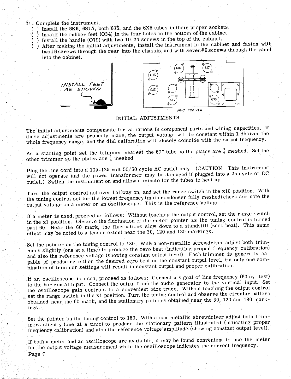
21. Complete the instrument.
( ) Install the6K6 6SL7, both 6J5, and the 6X5 tubes in their proper sockets.
( ) Install the rubber feet (034) in the four holes in the bottom of .the cabinet.
( ) Install the handle (079) with two 10- 24 screws in the top of the cabinet.
. ( ) After making the initial adjustments, install the instrument in the cabinet and fasten with
two #6 screws through the rear into the chassis, and with seven#6 screws through the panel
into the cabinet.
AG- 7 TOP VIEW
INITIAL ADJUSTMENTS
The initial adjustments compensate for variations in component parts and wiring capacities. If
these adjustments are properly made , the output voltage will be constant within 1 db over the
whole frequency range, and the dial calibration will closely coincide with the output frequency.
As a starting point set the trimmer nearest the 6J7 tube so the pla~es are ~ meshed. Set the
other trimmer so the plates are i- meshed.
Plug the line cord into a 105- 125 volt 50/60 cycle AC outlet only. (CAUTION: This instrument
will not operate and the power transformer may be damaged if plugged i11to a 25 cycle or
outlet.) Switch the instrument on and allow a minute for the tubes to heat up.
Turn the output control not over halfway on, and set the range switch in the x10 position. With
the tuning control set for the lowest frequency (main condenser fully meshed) check and note the
output voltage on a meter or an oscilloscope. This is the reference voltage.
If a meter is used, proceed as follows: Without touching the output control, set the range switch
in the xl position. Observe the fluctuation of the meter pointer as the tuning control is turned
past 60. Near the 60 mark, the fluctuations slow down to a standstill (zero beat). This same
effect may be noted to a lesser extent near the 30, 120 and 180 markings.
Set the pointer on the tuning control to 180. With a non-metallic screwdriver adjust both trim-
mers slightly (one at a time) to produce the zero beat (indicating proper frequency calibration)
and also the reference voltage (showing constant output level). Each trimmer is generally ca-
pable of producing either the desired z~ro beat or the constant output level, but only one com-
bination of trimmer settings will result in constant output and proper calibration.
If an oscilloscope is used, proceed as follows: Connect a signal of line frequency (60 cy. test)
to the horizontal input. Connect the output from the audio generator to the vertical input. Set
the oscilloscope gain controls to a convenient size trace. Without touching the output control
set the range switch in the xl position. Turn the tuning control and observe the circular pattern
obtained nearthe 60 mark, and the stationary patterns obtained near the 30 , 120 and 180 mark-
ings.
Set the pointer on the tuning control to 180. With a non-metallic screwdriver adjust both trim-
mers slightly (one at a time) to produce the stationary pattern illustrated (indicating proper
frequency calibration) and also the reference voltage: amplitude (showing constant output leve 1).
If both a meter and an oscilloscope are available, it may be found convenient to use the meter
for the output voltage measurement while the oscilloscope indicates the correct frequency.
I?age 7

The calibration may. be affected slightly when the instrument is instaHedin the cabinet. The
adjustments should therefor be rechecked and possibly readjusted to compensate for such vari-
ations.
------
t--
REFERENCE
VOLTAGE.
AMPLITUDE
-----,---
1---
The fluctuation of the meter pointer at 60 cycles is the result of pickup ' of stray electrostatic
fields '(hum pickup) by the tuning condenser and other parts in the grid circuit of the 6J7 tube.
Installation in the cabinet eliminates this effect.
IN CASE OF DIFFICULTY
If the instrument fails to perform properly, locate the trouble as outlined.
1. Check the wiring by following each wire on the pictorial and in the instrument, inspecting the
soHered connections on each end, and then checking off that wire in the pictorial with, a col-
ored pencil. This will reveal mistakes and omissions in wiring, which is the most frequent
cause of difficulties.
2. Check the voltages between tube socket pins and chassis. The readings should come reason-
ably! close to the values tabulated below, if a vacuum tube voltmeter with 11 megohm input
resistance is used. Other type meters may give considerably lower readings. .If a voltage
reading fails to check with the tabulation, investigate the portion of the circuit involved (by
checking the resistors and condensers for instance), and determine the cause.
Socket . F
Pin 6J7 6K6 6SL7 6J5 6J5 6X5
. 1 15 NEG
7 AC 110- 140
130-170 130- 170 210-250 110- 150 210-250AC
50- 140- 180 110- 140 Tie Point Tie Point .No Conn.
3 N 230-270 210-250AC
Tie Point Tie Point 120- 150 No Conn. Tie Point No Conn.
10- 280-320
*VOLTAGE BETWEEN PINS IS 5-7 VOLTS AC.
Voltage readings may be expected to fall within the ranges indIcated. Headings outside these
ranges are not necessarily indicative of faulty operation.
Page 8
3. 'If.~ part is found to be faulty, please return it promptlyfor a replacement, and attach a letter
to the package describing the nature of the fai.1lt.
4. If tl1e generator operates improperly, particularly on th~ lowest band, the feedback may re-
quire adj\,1stment. A slight adjustment in the 3600 ohm resistor (Gll) by adding 50 ohms or
more in series or 100 000 ohms or less in parallel (shunt) may correct the condition.
5. Should the procedure outlined above fail to clear up the difficulty, write to the Heath Com-
pany, describing the trouble encountered by giving all, possible details, such as voltage read-
ings. We will attempt to analyze your trouble and advise YOll accordingly.
,IN ALL CORRESPONDENCE REFER TO THIS INSTRUMENT AS THE MODEL AG'-7 AUDIO
GENERA TOR.
CIRCUIT DESCRIPTION
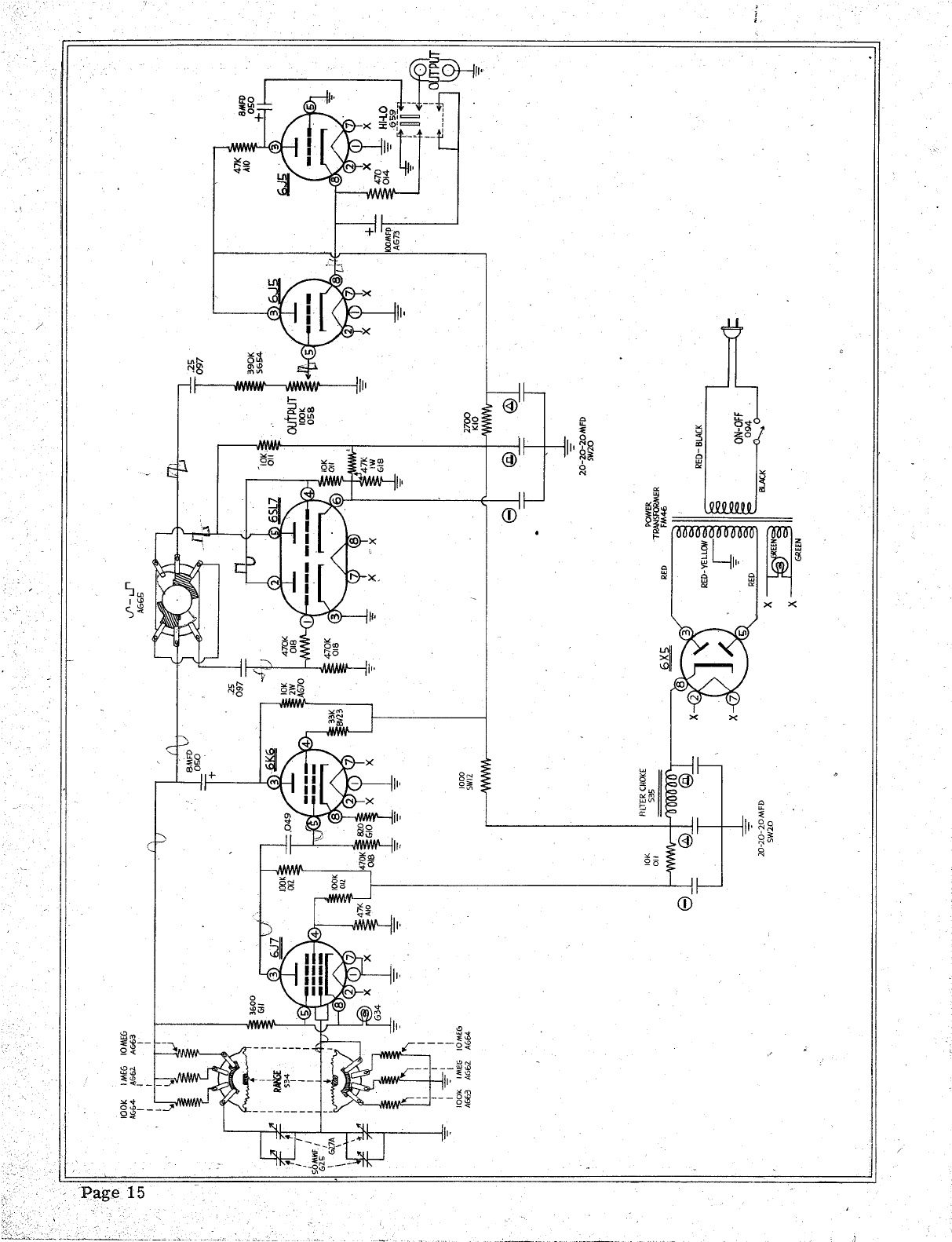
OSCILLATPR. The oscillator section is a two stage resistance coupled amplifier with both
positive and negative feedback over both stages. Positive feedback is applied through a fre-
quencyselective circuit comprising resistors and condensers. This section determines the os-
cillator frequency. The negative feedback is used to stabilize the operation of the circuit, and
is appLied through a voltage dividing n~twork. A part of this network consists of a non linear
resistor (3 watt lamp). This lamp controls the amount of feedback and thus provides stable
operating conditions.
CLIPPER. The square wave is generated by feeding the sine wave output from the oscillator
into a clipper circuit. This circuit uses a two stage direct coupled amplifier. The signal over-
/ loads the amplifiers and thus clips the peaks of the sine wave input. Thus only a square wave
remains.
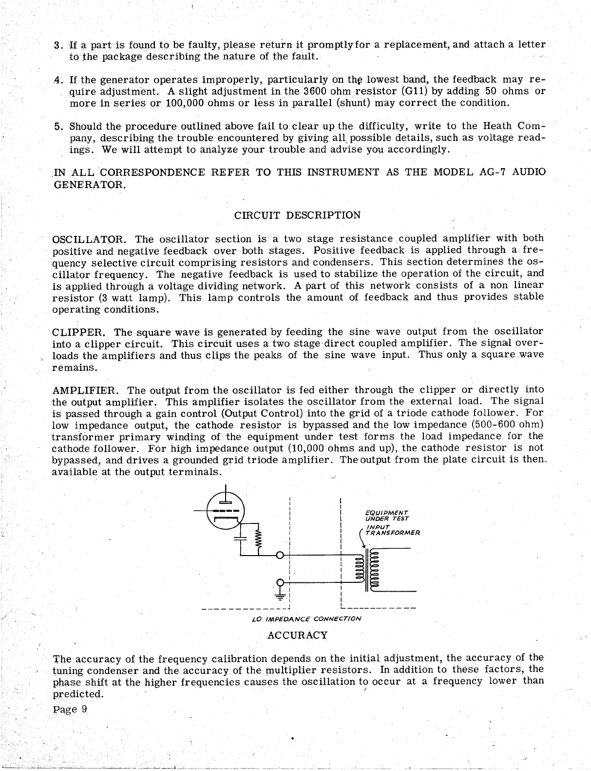
AMPLIFIER. The output from the oscillator is fed either through the clipper or directly into
the output amplifier ~ This amplifier isolates the oscillator from the external load. The signal
is passed through a gain control (Output Control) into the grid of a triode cathode follower. For
low impedance output, the cathode resistor is bypassed and the low impedance (500-600 ohm)
transformer primary winqing of the equipment under test forms the load impedance for the
cathode follower. For high impedance output (10 000 ohms and up), the cathode resistor is not
bypassed, and drives a grounded grid triode amplifier. The output from the plate circuit is then~
available at the output terminals.
-=- I
------------_
L------- -
---
LO IMPEDANCE CONNECTION
ACCURACY
'rl1e accuracy of the frequency calibration depends on the initial adjustment, the accuracy of the
tuniIlg ~ondenser and the accuracy of the l1lUltiplier resistors. In addition to these factors, the
phase shift at the higher frequencies causes the oscillation to occur at a frequency lower than
PJ'"edi~ted.
Page 9

This phase shift will vary with wiring capacity and the oscillator frequency at the high end of tQ€
highest range may fall short by as much as 10% of the calibration. On the lower ranges, the
calibration should fall within i 3%.
For precision work, the use of Lissajous figures derived from the power line frequency present
convenient calibration points on the lower frequency ranges.
APPLIC A TION
This instrument may be used as a source of sine wave audio voltage with a distortion of less
than 1% at any frequency between 20 cycles and 20 000 cycles.
The high impedance output circuit is designed to work into a high impedance load. The maximum
output voltage with 1% distortion varies with the load resistance and is approximately 1 volt at
000 ohms, 5 volts at 30 000 ohms and 10 volts .at 100 000 ohms. The source impedance of the
instrument is approximately 15 000 ohms.
The low impedance output circuit is designed to work into a low impedance transformer primary
with negligible DC resistance. The maximum output voltage with 1% distortion varies with the
transformer characteristics (and therefor the frequency) and the load resistance , and is approx-
imately 0.5 volt at 500 ohms, 1.0 volt at ~OOO ohms and 1.5 volts at 2000 ohms. The source
impedance is approximately 700 ohms. Resistance loads of 500 to 2 000 ohms may be used with a
slight decrease in maximum output voltage with 1% distortion.
The square wave output, while usable over the full frequency range covered, is substantially
square over a range of frequencies between 60 cycles (5% tilt) and 6000 cycles (5% round off).
The sine wave output is suitable for applications when a constant level low distortion source of
audio frequency signals is required, such as fidelity and distortion measurements on amplifiers
speaker testing and operation of A. F. bridges.
The square wave output is particularly useful in applications requiring rapid determination of
frequency and phase response characteristics of amplifiers and networks.
BIBLIOGRAPHY
For additional reading material about Audio Generatorsand their applications, we suggest the
many articles in the popular radio and service magazines, such as:
RADIO AND TELEVISION NEWS (RADIO NEWS)
January
September
August
November
December
January
March
June
August
September
October
November
1944
1945
1946
1946
1946
1947
1950
1950
1950
1950
1950
1950
Square 'Wave Testing of Amplifiers
Audio Oscillators and Their Applications
Audio Oscillators
Low Cost Audio Oscillator
Simple Square Wave Generator
C Audio Oscillator
Square Wave Clipper
Audio Oscillator and VTVM
100 Kc. Square Wave Generator
Wide Range R-C Oscillator
Square Wave Generator
C Beat Frequency Oscillator
ELECTRONICS
September 1948 Low Frequency Oscillator
RADIO ELECTRONICS (RADIO CRAFT)
August-September 1947
May 1948
July 1948
August 1948
October 1948
February 1949
August 1949
July 1950
July 1950
Bandspread Audio Oscillator
Laboratory Type Oscillators
Audio GeI\erator
Single Control Audio Oscillator
Calibrating Audio Oscillators
Versatile Audio Oscillator
Laboratory Square Wave Generator
Square Wave Analysis
Extended Range Oscillator
An excellent description of the principles of R-C oscillators maybe found in the "H. P. Journal
Volume 1 Nos. 3 and 4, November and December 1949, published by the Hewlett-Packard Com-
pany, Palo Alto, California, under the title of "Design Notes on the Resistance-Capacity Oscil-
hitor Circuit. " The Hewlett-Packard name has for years been synonymous with R-C oscillators
as they manufacture the greatest variety of the finest equipment of this type.
SERVICE
If correspondence fails to clear up operational difficulties of the completed instrument, the fa-
cilities of the Heath Company Service Department are available.
The Heath Company Service Department will inspect your instrument and put it into operating
condition for a service charge of $5.00 plus the cost of any new parts or extra labor required
because of damage through improper construction.
As an assurance to the customer that the Heath Company stands solidly behind all its products
and will do its utmost to insure proper operation of every kit, it is making this service available
until one year from purchase date.
After this time limit, repair work will sUll be accepted, but the cost of repairs will be deter-
mined after an examination by the Heath Company Service Department, and the customer will
be advised of the cost before work is begun
NOTE: Before returning this unit, be sure all parts are securely mounted. Attach. a tag, giving
name, address and trouble experienced, to the unit. Pack in a rugged container, preferably wood
using at least three inches of shredded newspaper or excelsior on all sides. DO NOT use folded
newspaper. DO NOT ship in original carton only. Ship by prepaid express if possible. Return
shipment will be made by express collect.
NOTE that a carrier cannot be held liable for damage in transit if packing, in HIS opinion, is in-
sufficient.
Prices subject to change without notice. The Heath Company reserves the right to change the
design without incurring liability for equ!pment previously supplied-
Page 11
.---... .. /. ..'

WARRANTY
The Heath Company limits its warranty on any part supplied with any Heathkit (except tubes
meters, and rectifiers, where the original manufacturer s guarantee only applies) to the re-
placement within three (3) months of said part which, when returned with prior p~rmission, post...,
paid, was, in the judgment of the Heath Company, defective at the time of sale.
..
The assembler is urged to follow the instructions exactly as provided. The Heath Company as-
sumes no responsibility or liability for any damages or injuries sustained in the assembly of the
device or in the operation of the completed instrument.
HEA TH COMPANY
Benton Harbor, Michigan
Page 12
, "-.

Part Parts
No. P€r
Kit
Resistors
014
G10
SW12
K10
G11
011
AG70
BV23
A10
G18
:()12
SG54
018
AG64
AG62
AG63
Cqndensers
049
097
050
AG73
SW20
G25
G27A
Description
470 ohms
820 ohms
1000 ohms
2700 ohms
3600 ohms
10 K ohms
- 10 K ohms 2 watt
33 K ohms
47 K ohms
47K ohms 1 watt
100 K ohms
390 K ohms
470 K ohms
100 K ohms, precision
1 Meg ohm, precision
10 Meg ohm, precision
1 MFD
25 MFD
8 MFD-475 V
100 MFD-15 V
20-20-20 MF'D- 300 V
50 MMF Trimmer
4 section Tuning
Control- -Switches
058 100 K ohm Control
S34 3 pas. Rotary Switch
AG65 2 pas. Rotary Switch
G59 DPDT Slide Switch
094 SPST Slide Switch
Sockets--Terminal Strips--Knobs
AR32 Octal Tube Sockets
G37 Candelabra Lamp Socket
S32 2 lug Terminal Strip
SW37 3 lug Terminal Strip
051 Pointer Knobs
G38 Indicator Knob
Tubes- -Lamps
AG69
G43
G42
A48
V30
G34
039
6J7 (GT) Tube
6K6GT Tube
6SL7GT Tube
6J5 (GT) Tubes
6X5 (GT) Tube
3 watt Lamp
#47 Pilot Lamp.
Pilot Light Assembly
040 Nut
041 Bushing
042 , Jewel
052 Socket
Page 13
AG7 PARTS LfST
Part
No. Parts
Per Kit Description
Insulators - - Wafers- -Grommet
G29A Ceramic Insulators
IB31 Binding Post Insulator
SW43 Condenser Mounting Wafers
035 i 3/8" Grommet
Screws --Nuts- -Washers
AG74 . 4-40x3/16 Screws
G31 6 4-40 x 3/8 Screws
K16 3 6-32 x 3/16 Screws
031 27 6-32 x 3/8 Screws
G53 3 6-32 x 1- Screws
G52 3 8-32 x 3/8 Screws
030 2 10-24 Handle Screws
0102 #6 Sheet Metal Screws
. S22 33 6-32 Nuts
TP16 2 8-32 Nuts
033 Control Nuts
TS72 33 #6 Lockwashers
BR36 #8 Lockwashers
0101 Control Lockwashers
028 Nickel Washers
027 Fibre Flat Washers
037 Solder Lugs
G32 Spade Bolts
Bushings - -Shaft --C oupling
G30 Panel Bushings
G33 Shaft
G39 Shaft Coupling
Terminal Hardware
IB32 Binding Post Bases
IB33 Thumbscrews
IB34 10-32 Nuts
IB36 #10 Lockwashers
IB37 no Fibre Washers
IB38 #10 Nickel Washers
0109 #10 Solder Lugs
Sheet Metal Parts
AG67 Chassis
AG66 Panel
AG71 Switch Bracket
AG68 Power Supply Shield
AG72 Trimmer Mtg. Bracket
PS10 Cabinet
079 Handle
Miscellaneous
FM46
S35
K18
034
078
077
081
Power Transformer
Filter Choke
Grid Cap
Rubber feet
Line Cord
Length Hookup Wire
Length Spaghetti
L- "' . -c,
" ~'--"-.-
018
470K
TIE KNOT FOR
.....-STRAIN RELIEF
A667
CHASSIS
I-""
C)1 oJ' - ...r
A6G!;
20-20~20MFD
5'1120
20-20-20MFD
SW20
094 .
0..,.,.
BLACK
cJI:
RED
EEN
GREEN
Table of contents
Popular Inverter manuals by other brands


SolarMax
SolarMax S series instruction manual

Sunways
Sunways STT-29.9KTL user manual

FRONIUS
FRONIUS Symo GEN24 6.0.Plus operating instructions

Heavy Duty Power Systems
Heavy Duty Power Systems HDI 7000RWB owner's manual

Sofar solar
Sofar solar SOFAR 7.5KTLM user manual

FRONIUS
FRONIUS Fronius Agilo 360.0-3 TL operating instructions


