PanelClaw clawFR 10 Degree User manual

9910045 RevF October 2020
Table of Contents
clawFR 10 Degree
Installation Manual
ANSI/UL 2703
System Fire Class Rating: Class A for low slope roofs with Type I & Type II Modules
Mechanical Load Rating: See Appendix B: UL 2703 Grounding
Introduction & Safety Overview 2
Storage, Array Construction, and
O&M considerations
3
System Components 4
Tools, Torque, Construction Aid &
Accessories
5
Construction Aid Setup 6
Build Assemblies 7
Build North Array Row 8
Build Remaining Rows 9
Place Ballast 10
Install Module Low Side 12
Install Module High Side 13
Continue Installing Modules 14
Install Deflectors 15
Cam & Lock Claw Inspection 16
Electrical Grounding 17
Appendix A-G 18-27

9910045 RevF October 2020
Introduction
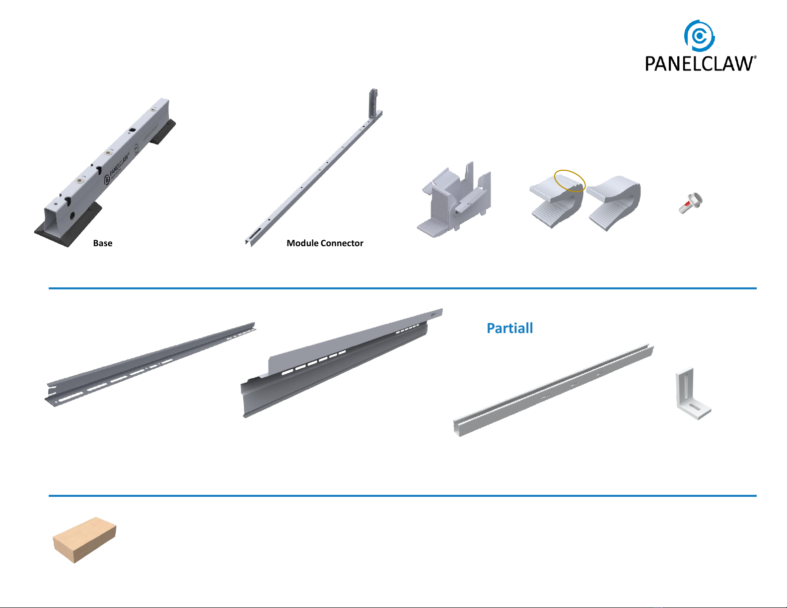
The clawFR 10 Degree flat roof mounting system is
comprised of four major components that intuitively
assemble into a support structure for photovoltaic (PV)
modules.
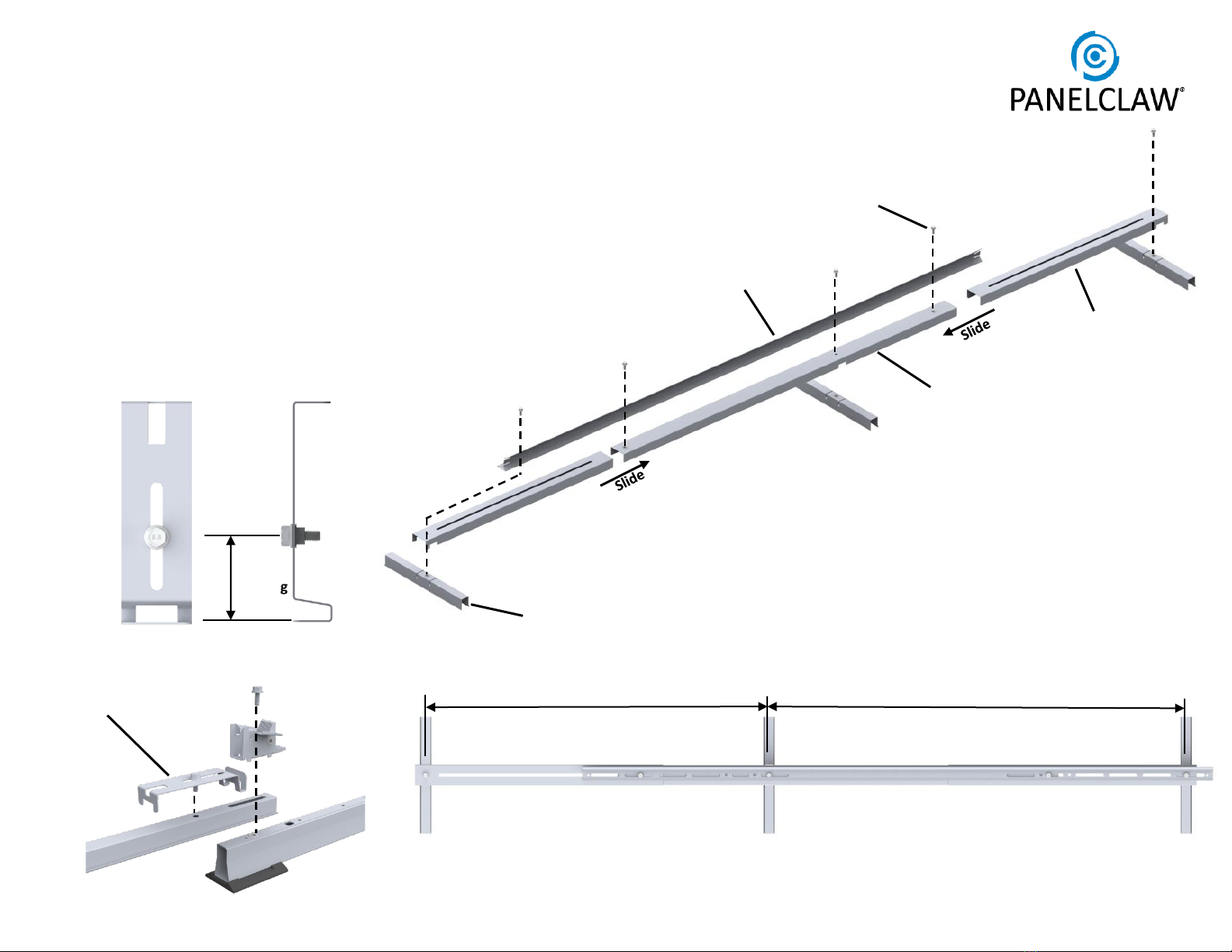
This installation manual explains how to build a PV array
using clawFR 10 Degree.
PAGE 2
PRIOR TO INSTALLATION, READ THE SAFETY PROVISIONS
ATTACHED IN Appendix A: Safety AND REVIEW THIS INSTALLATION
MANUAL IN ITS ENTIRETY.
A CORROSION INSPECTION ONE YEAR AFTER INSTALLATION AND
ONCE EVERY THREE YEARS THEREAFTER IS REQUIRED TO MAINTAIN
THE PRODUCT WARRANTY. VISIBLE SURFACE RED RUST ON ZAM®
COATED STEEL COMPONENTS MUST BE LOCALLY COATED WITH A
COMMERCIALLY AVAILABLE GALVANIZED PAINT OR COATING TO
MAINTAIN PRODUCT WARRANTY.
Mechanical Attachments
THIS INSTALLATION MANUAL DOES NOT COVER THE
SELECTION OR INSTALLATION OF MECHANICAL
ATTACHMENTS INCLUDING MATERIALS AND FASTENERS
USED TO SECURE AND/OR SEAL MECHANICAL
ATTACHMENTS TO THE ROOF. PLEASE SEE OEM
PROVIDER INSTALLATION MANUALS AND RELATED
LITERATURE. A LIST OF OEM PROVIDERS IS SHOWN
BELOW.
OEM MECHANICAL ATTACHMENT PROVIDERS:
•Anchor Products: www.anchorp.com
•OMG Roofing Products: www.omgroofing.com
•Facet: www.sustainabletechnologiesllc.com
Safety Overview
Safety is an essential part of every PV installation and every construction
site. It is imperative to plan ahead for any safety concerns and hazards to
promote safe work practices during installation. This section does not claim
to address or support all safety concerns that may arise during the
installation of PanelClaw mounting systems or any other aspect of the work
being performed. Before beginning work, installers should refer to all local
and federal safety, health, and regulatory requirements to assure
compliance. Refer to OSHA Part 1926 and its related Subparts for federal
construction related regulations and standards.
Appendix A: Safety outlines some of the major hazards to be aware of during
the installation of PanelClaw products.
EXCEPT FOR DEFLECTORS, ALL RACKING COMPONENTS IN EACH SUBARRAY AND THEIR CONNECTIONS, BALLAST, AND MECHANICAL
ATTACHMENTS (IF ANY IN DESIGN) MUST BE INSTALLED BEFORE MOUNTING MODULES. WHEN FORECASTED WIND GUSTS EXCEED
25% OF THE WIND SPEED LISTED IN THE SITE CRITERIA TABLE OF THE RACKING CONSTRUCTION SET, DEFLECTORS MUST BE INSTALLED
ON ALL MOUNTED MODULES TO AVOID POSSIBLE SYSTEM DAMAGE.

9910045 RevF October 2020
Storage Considerations
PanelClaw recommends installing the racking
components shortly after delivery to the project site. If
clawFR components are not deployed immediately, they
should be stored in a well-ventilated, dry location.
Otherwise, moisture can form between the packed
components which may cause staining and/or white
rust. Significant white rust formation may decrease the
coating service life and, in extreme cases, the
component performance.
If storage onsite is unavoidable, remove the plastic
and/or carboard wrapping from the exterior of the
packaging and cover with canvas or place components
under an open sided tent. Note the use of a plastic cover
does more harm than good as it prevents the product
from breathing and causes condensation. Storing parts
in any other manner is at the customer’s own risk.
PanelClaw is not liable for claims related to improper
storage and any such claims are not covered by the
product warranty.
PAGE 3
Operations & Maintenance
See O&M Manual, 9910050 found on PanelClaw.com, for
initial inspection recommendations including steps that can
be performed only during construction.
Sub Array Dimensions
Each PV system is unique and is frequently made up of
multiple sub arrays. The Racking Construction Set, which must
be onsite at all times during construction, details sub array
dimensions and location on the roof. Review the Racking
Construction Set in its entirety to prevent unnecessary rework
during site construction.
The furthest extent of the racking components or modules of
adjacent sub arrays, whichever defines the outermost array
boundaries, must be separated by at least the minimum
dimensions documented in the Racking Construction Set.
Refer to the general notes and the Minimum Clearance
Requirements table, if present, within the Racking
Construction Set.

9910045 RevF October 2020
Ballast Block: Solid cap concrete roof paver, conforms to ASTM C1491 standard and manufactured for freeze-thaw
resistance where applicable. See Appendix E for more details
System Components
PAGE 4
M6x16mm Bolt
2000697
Wind Deflector
2000887 [01/02/03/04]
Module Connector
5000507 [01/02] Cam
5000500
Base
5000502 [02/03]
Hardware Kit for
Mechanical
Attachment Strut
5000223
For Fully Attached or
Partially Attached Designs
Rail
2000695 Mechanical
Attachment Strut
2000830
See: 9910047 - Accessories Installation Manual
Cam Claw*
2000673 (1 pair of grooves)
2000815 (1 groove)
Pair of grooves
*Both SKUs are shown here. Check the Racking Construction Set to verify correct Cam Claw is received

9910045 RevF October 2020
Torque Setting
*
Fastening Operation
6 ft
-lb (8.1 Nm)
All System connections
except
Special Cases
4 ft
-lb (5.4 Nm)
Special Cases, See Appendix F
Spacer Stick
Construction Aids
Drill with torque limiter or Torque Wrench
10 mm Magnetic Socket
ALERT: NO IMPACT DRIVERS
Tools
Cam Spacer / Lock Claw Insertion Depth Gauge
Optional Accessories
Shim Pad
5000228
Optimizer Attachment
5000509
Wire Router
5000225 [01/02]
Base Pad
2000678
*+/-4% allowable during installation
Wire Clip
5000226
PAGE 5
Spacer Stick and Cam Spacer Kit
5000510
Note: Use of non-UL listed accessories, including non-metallic components, does not affect the system ANSI/UL 2703 certification.
Bolts which are installed into a pre-installed nut
are tightened to 6 ft-lb
Bolts which are installed into a pilot hole are
tightened to 4 ft-lb, See Appendix F
See: 9910047 - Accessories Installation Manual

9910045 RevF October 2020
1. Construction Aid Setup
2X
3X
1X
5X
Tip: L, S, and Cam Spacer dimensions are found in the
Racking Construction Set
1.1 Assemble the Spacer Stick and adjust to L & S dimensions.
All dimensions are measured from the Base centerlines.
Tip: To stiffen the Spacer Stick, place one Rail 2000695 on
the assembly as shown, shift the Rail to find a location
which allows for attachment with the specified bolts.
Tighten the bolts.
1.2 Insert the bolt and adjust the Cam Spacer to the Cam
Spacing dimension.
Adjust Spacer Stick
Spacing S
Spacing L
PAGE 6
Typical Cam
Spacer Usage
Cam Spacer / Lock Claw
Insertion Depth Gauge
Cam
Spacing
1X Rail 2000695

9910045 RevF October 2020
2. Build Assemblies
PAGE 7
2.1 Position components as required per assembly type and loosely
assemble the Cam, Module Connector and Base.
ALERT: Note location of orientation marker on Base “ ”
Tip: Base length may vary depending on the row spacing option.
Tip: Immediately tighten bolts to 6 ft-lb which are at the Tilt Arm
end of the assembly.
2.2 Use the Cam Spacer tool to correctly locate the Module Connector.
Tighten bolt to 6 ft-lb.
South
Assembly
Hole 2
Middle
Assembly
Hole 1
+ +
Base
(qty 1 or 2) Module Connector Cam
Hole 1
Hole 3
Hole 2
Tilt Arm
Hole 1
North
Assembly
Hole 3
North South
Assembly
Hole 2
Hole 3

9910045 RevF October 2020 PAGE 8
3. Build North Row
S
L
Tip: L, S, R and AEBE dimensions
are found in the Racking
Construction Set.
Tip: “S” spacings are module centered “L”
spacings are between modules.
Spacer Stick
S
L
ALERT: To ensure system
alignment, use the Spacer Stick
to align Module Connectors
before securing Rails
Place a Rail on all “S” spacings (module centered).
Rails at ends of rows must be flush with array edge.
Place a Rail on all “L” spacings (between modules) on
top of and overlapping the Rails on the S spacing.
Install bolt and tighten to 6ft-lb.
S
L
3.3
ALERT: Rail on “L” Spacing is ALWAYS on
top of Rail on “S” Spacing. This installation
sequence is critical to system
performance.
Tip: Rail has two holes. Consult the Racking
Construction Set for appropriate hole use.
Snap North Edge, Base Edge, and Array Edge lines.
Tip: Snap Array Edge lines on one or both array
edges (row ends) and snap Base Edge line on the
edge where module mounting will begin.
3.1
See Racking Construction Set for
AEBE dimension.
If not shown then: AEBE
Place North Assemblies with the Base Pads along the
North Edge line. The first and last North Assemblies
should be placed with the edge of the Base Pads on
the Base Edge line.
Tip: Raise Tilt Arms after securement of assembly.
3.2
Tip: Base Edge
is in line with
Base Pad
Base edge
measured to
Pad edge

9910045 RevF October 2020
Spacer Stick
L
Tip: Raise Tilt Arms after
bolting assemblies in
preparation for Rail
installation.
S
4.2 Install Rails throughout the array using the same
steps described on the previous page. Alternating
between “S” and “ L” Spacings. Install bolt and
tighten to 6 ft-lb.
ALERT: To ensure system alignment, use the spacer
stick to align Module Connectors before securing
Rails.
ALERT: See Appendix F for instructions on installing
Rails on edges with cutouts.
PAGE 9
4. Build Remaining Rows
Place Middle or South assemblies onto
Assemblies from previous row and bolt to 6 ft-lb.
Tip: Racking Construction Set clearly indicates
hole selection. Using the wrong hole will result in
an array which does not match site plan.
4.1
Middle or South
Assembly
Choose correct
hole Note
Orientation
ALERT: Southern Edge Rails face the opposite
direction; bolts securing these rails are tightened
to 6ft-lb.

9910045 RevF October 2020
Attach Rail to
location closest
to Cam.
Rail Position for 5-8 Ballast blocks
PAGE 10
5. Place Ballast
Tip: The Racking Construction Set identifies where Ballast is to
be installed. Mark the roof with chalk to speed up installation.
5.1 Install a Rail onto array in locations where Ballast is required.
Bolt to both Module Connectors and tighten to 6 ft-lb.
ALERT: Every Rail must be fastened to two Module Connector
assemblies.
Tip: Ballast and Rails are only placed on “S” spacings. Center
Rails on the “S” spacing.
5.2 Place Ballast onto Rails. If rapid cyclic movement of system is
expected e.g. due to seismic activity or building vibration from
activities within or nearby the structure, bend the Rail tabs to
secure Ballast.
ALERT: Install Mechanical Attachments before going to next
step. See: 9910047 - Accessories Installation Manual
1
2
5
8
4Ballast Quantity
S
Rail Position for 1-4 Ballast blocks
Attach Rail to
location closest to
Tilt Arm.
Bend tabs at ends of Rail.
(See 5.2 to determine if required)
Bend Tabs to
capture ballast
as required.
ALERT: Do not step
on ballast blocks
Tip: Installing the north row ballast blocks helps keep the
racking structure from moving as the rest of the array is built.

9910045 RevF October 2020 PAGE 11
5. Place Ballast (Continued)
1 2 3 4
5 6 7* 8*
*ALERT: Modules longer than 2100 mm with
7 or 8 ballast blocks require two (2) Rails.
Install Rail 2 on top of Rail 1 and tighten to
6ft-lb.
Rail 1
Rail 2
5.3 Ballast must be placed as shown. Ballast quantity affects the Ballast placement on the Rails
and in some cases additional Rails are required as noted below.

9910045 RevF October 2020
6. Install Module Low Side
PAGE 12
Cam Claw aligned
6.1
Cam Seat
Place module on Cam Seat and
align with Array Edge.
Tip: Ensure the module is vertical
and flush with Seat.
ALERT: Cam Claw mis-aligned.
R
Tip: R dimension is found in
the Racking Construction Set.
Tip: Installing modules
starting at the south array
edge provides more working
room and speeds installation.
ALERT: Do not leave modules in
vertical position, go immediately to
next installation step (high side install).
Cam Claw
Place Cam Claw over module flange.
Apply a small downward force to
make sure it is properly seated.
6.2
ALERT: Install Mechanical Attachments before installing modules.
See: 9910047 - Accessories Installation Manual
ALERT: When forecasted wind gusts exceed 25% of
the wind speed listed in the site criteria table of the
Racking Construction Set, Deflectors must be installed
on all mounted modules to avoid possible system
damage.
Example of a typical good Cam Claw install,
after the module has been rotated down
and high-side has been installed

9910045 RevF October 2020
7. Install Module High Side
PAGE 13
DO NOT REST MODULE
BACKSHEET ON TILT ARM
Tip: Use two hands when engaging Lock
Claw to ensure correct installation.
LOCK CLAW UNEVENLY
ENGAGED
Tilt Arm
Tongue
Lock Claw
Rotate module down and rest the module
frame on the top of the Tilt Arms.
Tip: Make sure the Tilt Arms are fully
raised.
7.1
Support module while carefully
rotating the Tilt Arm just
enough to rest the module
frame on the Lock Claw tongue.
7.2
Pull the Tilt Arm forward until the Lock
Claw is fully engaged onto the module
frame flange.
7.3
LOCK CLAW NOT FULLY
ENGAGED
Tip: See Appendix G for Lock Claw
reset method.

9910045 RevF October 2020 PAGE 14
7. Continue Installing Modules
Use Cam Claw as spacer to set spacing between adjacent
modules.
R
Tip: R dimension is
found in the Racking
Construction Set.
ALERT: Check the R dimension every 5th
module and adjust spacing between
adjacent modules as needed.

9910045 RevF October 2020
8. Install Deflectors*
PAGE 15
Place the bottom edge of the Deflector in the
Deflector Seat near the bottom of the Tilt
Arm.
Fasten to Tilt Arm with bolt and tighten to
6ft-lb.
Deflector
Seat
Center Deflector on module
for all non edge modules
Tip: On array edge Deflectors can be
installed flush to module/array edge.
Tip: Adjacent Deflectors will overlap
(adjacent deflector not shown).
8.1
* Consult the Racking Construction Set for deflector requirement. Each Array will specify required Deflectors per array.
ALERT: When forecasted wind gusts exceed 25%
of the wind speed listed in the site criteria table
of the Racking Construction Set, Deflectors must
be installed on all mounted modules to avoid
possible system damage.

9910045 RevF October 2020 PAGE 16
Lock Claw Insertion Gauge configuration and use
Place gauge against Lock Claw and underside
of module.
Select a Lock Claw which has been
confirmed to be installed correctly
through visual inspection.
The Tilt Arm and Lock Claw should
be aligned with the module frame
and the Lock Claw fully engaged
on the frame.
Mark line on gauge to finish setup.
Use gauge to confirm full Lock Claw
engagement-line must be visible.
9. Cam & Lock Claw Inspection
Inspect Cam side module connection
Module and Cam are near flush.
Module and Cam have a large
non-uniform gap.
Cam installation can be quickly visually
inspected (no gauge is available or
required) by comparing a known good
installation with all other installations.
Some gap between Module and Cam
is permissible. The graphics are
representative only; actual installation
geometry varies by module vendor
and part number. If it is not clear the
module low side connection is good,
contact PanelClaw for assistance.
ALERT: Verify correct installation by
lifting up on the module near the Cam
and making sure no movement occurs.

9910045 RevF October 2020
Electrical Grounding
Please consult with national and local building code(s) for
complete grounding requirements for your installation. The
clawFR grounding method conforms to ANSI/UL 2703 and is
certified by SolarPTL for use with approved photovoltaic
modules listed under ANSI/UL 1703 and/or ANSI/UL 61730.
Installers can quickly and easily establish ANSI/UL 2703
certified electric bonds between all connected array
components, including modules and mounting system
components, without the use of additional grounding
devices, e.g. ground lugs and copper wire. At least one
ground lug must be used to ground all strings within a
physical sub-array provided the fuse rating for each string
does not exceed 30 amps. Installers may opt to use multiple
lugs per sub-array for redundancy. When grounding devices
are installed according with the approved methodology and
capacity below, the connections described above meet all
the requirements outlined in NEC 690.43.
Grounding Instructions
For modules that have been evaluated for use with clawFR 10 Degree,
please follow the instructions below in Appendix B: UL 2703 Grounding.
Additional information regarding ANSI/UL 2703 and the specific list of
evaluated modules included in PanelClaw’s UL listing can be found in
the “clawFR UL Overview and Module Listing” document (available at
www.panelclaw.com).
For modules that have not been evaluated for use with clawFR, please
follow the instructions below in Appendix D: Electrical Grounding (Non
2703 PV Module).
ALERT: During grounding and bonding ensure there is separation
between bare copper and aluminum or ZAM coated steel components.
PAGE 17

9910045 RevF October 2020
Appendix A: Safety
PAGE 18
The subsections below outline some of the obvious / major hazards that could exist during the installation or O&M of PanelClaw products
and are divided to bring a level of clarity to such hazards. Some sections do not apply to all PanelClaw product lines and such exclusions are
noted within each section.
Electrical Hazards: PanelClaw products are purely mechanical and do not contain any electrically live parts. When a photovoltaic module is
exposed to sunlight it is electrically live and cannot be turned off. As soon as modules are installed using a PanelClaw system, an electrical
shock hazard is present. All personnel on site should coordinate to ensure that such electrical hazards are clearly communicated. It is advised,
at a minimum, that all personnel utilize caution and proper Personal Protective Equipment as outlined in that section. Only electrically
qualified personnel should perform PV module installation. Refer to OSHA Part 1926 Subpart K –Electrical and NFPA 70E for additional
information.
Environmental Hazards: Look for hazards associated with water and snow loading if observed upon entry into the array area. Standing water
increases the likelihood of electrical shock if the PV electrical system is compromised in any way. Severe snow loads can result in module
and/or racking damage and, in extreme cases, electrical hazards.
Fall Hazards: This section only applies to clawFR® products installed on locations six feet or higher above grade. Proper fall protection should
be in place at all work sites. There are many fall protection solutions readily available to help reduce exposure to fall hazards. These may
include personal fall arrest systems, safety nets, guardrails, and flagged setbacks from all roof edges as outlined in OSHA Part 1926 Subpart M
–Fall Protection.
Trip Hazards: All PanelClaw arrays have elevated components that are installed above grade or above a roof surface. Such hazards should be
identified and caution should be taken to avoid tripping over such components. Refer to the Fall Hazards section specifically if working with
the clawFR product line. Make sure to pick up and not drag your feet when working on site, and always pay attention to your path of
movement to note any obstructions that could create a trip hazard.
Lifting Hazards: The PanelClaw installation process involves lifting of heavy items that could lead to personal injury and damage to property.
All personnel should be trained in the proper procedures for manually lifting. Evaluate an object’s size and weight prior to lifting, and follow
these general guidelines for lifting:
1. Assess the lift and know the object weight.
2. Bend at the knees and get a good grip.

9910045 RevF October 2020
Appendix A: Safety (Continued)
PAGE 19
3. Keep back straight and lift straight up with legs without twisting. It is important to lift with the legs and not the back.
4. If an object is too large or heavy, ask for help and do not attempt to lift by yourself. In the case that mechanical assistance (e.g.
crane, forklift, etc.) is required to complete the lifting operations, all machine operators of such devices should be licensed and
trained.
Material Handling: All PanelClaw parts and components are made of aluminum and steel alloys and utilize stainless steel assembly
hardware. These materials are considered non-toxic and require no special handling procedures. Metal components may have sharp edges,
so be sure to handle with care and utilize proper personal protection equipment, especially gloves, during handling. Refer to OSHA Part
1926 Subpart H –Materials Handling, Storage, Use, and Disposal for additional information.
Personal Protective Equipment (PPE): All personnel should utilize and implement proper PPE per OSHA requirements. Refer to OSHA
requirements for proper use and implementation of PPE. The following items are suggested as a minimum to avoid injury based on the
installation procedure outlined in this manual:
1. Appropriate work clothing
2. Electrically insulated hard hat
3. Protective eyewear
4. EH rated safety boots
5. Gloves
6. High-visibility safety vest
7. Hearing protection
If any PPE appears to be defective, stop the use of such equipment immediately, and ensure it is replaced before work continues. Refer to
OSHA Part 1926 Subpart E –Personal Protective and Life Saving Equipment for additional information.
Hand and Power Tools: Access to all hand and power tools should be regulated and controlled at all times on site to prevent improper use
and related injuries. When not in use, all equipment should be stored in a secured location. Only personnel who have been properly
trained in the safe operation of any potentially dangerous tool should be allowed access. All required tools to perform the installation of
PanelClaw racking are outlined in the installation procedure. All tools should be inspected daily and before use by the operator. If any tool
appears to be defective, stop the use of such equipment immediately, and ensure it is replaced before work continues. Electrical power
tools should follow proper lock-out tag-out procedures per OSHA requirements. Refer to OSHA Part 1926 Subpart I –Tools –Hand and
Power for additional information.

9910045 RevF October 2020
Appendix B: UL 2703 Grounding
The clawFR 10 Degree flat roof system may
be used to ground and/or mount a PV
module complying with ANSI/UL 1703 or
ANSI/UL 61730 only when the specific
module has been evaluated for grounding
and/or mounting in compliance with the
included instructions. For a list of modules
which have been evaluated see PanelClaw’s
“clawFR UL Overview and Module Listing”
(see www.panelclaw.com).
A periodic re-inspection of the system shall
be performed for loose components, loose
fasteners, and any corrosion. If found, they
should be immediately replaced or remedied
in accordance with the system installation
instructions.
System Ground Path
The system ground path “grid” is established throughout the array by the interconnection of system components. Specifically, in the column
direction via the Base and Module Connector connections and in the row direction via the Rail connections. A Tyco lug connected to the Rail
establishes a point of connection for the EGC at one location with a contiguous array. All modules are grounded to the system through their
Cam to Module connection.
Note: The presence of aPV module does not affect the bonding ability of the clawFR system components. More precisely, the grid provides
a means to ground PV Modules which have been evaluated for ANSI/UL 2703 grounding with clawFR.
PAGE 20
To DC
Grounding Path
Ground Lug
Tyco #2106831-1
Row
Column
Table of contents
Other PanelClaw Inverter manuals
Popular Inverter manuals by other brands

Morningstar
Morningstar SureSine 150 W quick start guide

Solectria Renewables
Solectria Renewables PVI 15KW Installation and operation manual

Power Electronics
Power Electronics SD700 Series Hardware and installation manual

Hypontech
Hypontech HPS-1500 Quick installation guide

Adlee Powertronic
Adlee Powertronic Adleepower AS1 instruction manual

Samlexpower
Samlexpower PST-1000F-12 owner's manual

Baldor
Baldor TS25 Installation & operating manual

Peak Scientific
Peak Scientific NG2000A user manual

Medora
Medora SolarBee SB10000PW owner's manual

YASKAWA
YASKAWA XGI 1000-65/65 Installation and operation guide

Bohmer-AG
Bohmer-AG i2500W manual

Panasonic
Panasonic U-200PE1E8 Technical data & service manual