Solar Stik Hybrid Power System 500 User manual

January 2020
SYSTEM SETUP AND OPERATION
MANUAL FOR THE
HYBRID POWER SYSTEM 500
Version 1.0
Updated:20200113
DISTRIBUTION STATEMENT A. Approved for public release; distribution is unlimited.
This manual provides instructions for setting up, starting, running, and maintaining the Hybrid
Power System (HPS) 500. The current HPS 500 is congured to provide 500 watts constant power
to a load using power generated only from the included photovoltaic (PV) arrays. The number
of arrays assigned to the HPS will vary as they are subject to the geographic and environmental
conditions in which they will be operated.
The HPS 500 architecture is modular and scalable. It can be congured to include and manage a
fuel-driven generator or accept grid-utility power to supplement PV power if desired or required.
Information about connecting a fuel-powered generator or shore power is included in the Setup and
Operation Instructions.

January 20202 |
System Setup and Operation Manual for HPS 500
Contents
GENERAL INFORMATION, EQUIPMENT DESCRIPTION, AND THEORY OF OPERATION
Introduction to Hybrid Power Systems . . . . . . . . . . . . . . . . . . . . . . . . . . . . . . . . . . . . . . 8
The Hybrid Power System Flexible Open Architecture . . . . . . . . . . . . . . . . . . . . . . . . . . . . . .8
Important Safety Information and Instructions . . . . . . . . . . . . . . . . . . . . . . . . . . . . . . . . . . 9
Safety Information Labels . . . . . . . . . . . . . . . . . . . . . . . . . . . . . . . . . . . . . . . . . . . . . 9
Fire Hazard . . . . . . . . . . . . . . . . . . . . . . . . . . . . . . . . . . . . . . . . . . . . . . . . . . . 10
Recommended Fire Extinguisher . . . . . . . . . . . . . . . . . . . . . . . . . . . . . . . . . . . . . . . . 10
Electric Shock Hazard. . . . . . . . . . . . . . . . . . . . . . . . . . . . . . . . . . . . . . . . . . . . . . 11
Grounding the System. . . . . . . . . . . . . . . . . . . . . . . . . . . . . . . . . . . . . . . . . . . . . . 11
Environmental and Handling Precautions . . . . . . . . . . . . . . . . . . . . . . . . . . . . . . . . . . . . 12
Water . . . . . . . . . . . . . . . . . . . . . . . . . . . . . . . . . . . . . . . . . . . . . . . . . . . . . . 12
Impact . . . . . . . . . . . . . . . . . . . . . . . . . . . . . . . . . . . . . . . . . . . . . . . . . . . . . . 12
Dust . . . . . . . . . . . . . . . . . . . . . . . . . . . . . . . . . . . . . . . . . . . . . . . . . . . . . . . 12
Heat . . . . . . . . . . . . . . . . . . . . . . . . . . . . . . . . . . . . . . . . . . . . . . . . . . . . . . . 12
THEORY OF OPERATION
The HPS 500 Architecture, Function and Operation . . . . . . . . . . . . . . . . . . . . . . . . . . . . . . 13
Energy Storage – The Foundation of the HPS 500 . . . . . . . . . . . . . . . . . . . . . . . . . . . . . . . 13
Load Prioritization . . . . . . . . . . . . . . . . . . . . . . . . . . . . . . . . . . . . . . . . . . . . . . . . 14
Load Management . . . . . . . . . . . . . . . . . . . . . . . . . . . . . . . . . . . . . . . . . . . . . . . 14
Scaling and Modifying the HPS 500 . . . . . . . . . . . . . . . . . . . . . . . . . . . . . . . . . . . . . . 14
Minimum Battery Capacity Required for Optimal PRO-Verter Operation . . . . . . . . . . . . . . . . . . 15
“Overload” Conditions. . . . . . . . . . . . . . . . . . . . . . . . . . . . . . . . . . . . . . . . . . . . . . 16
Load Support . . . . . . . . . . . . . . . . . . . . . . . . . . . . . . . . . . . . . . . . . . . . . . . . . . 16
Lag Time and Surge Rates . . . . . . . . . . . . . . . . . . . . . . . . . . . . . . . . . . . . . . . . . . . 16
System Operation Models
DC-only/Inverter . . . . . . . . . . . . . . . . . . . . . . . . . . . . . . . . . . . . . . . . . . . . . . . . . 18
Hybrid . . . . . . . . . . . . . . . . . . . . . . . . . . . . . . . . . . . . . . . . . . . . . . . . . . . . . . 18
Load Support . . . . . . . . . . . . . . . . . . . . . . . . . . . . . . . . . . . . . . . . . . . . . . . . . . 18
Peak Power Delivery . . . . . . . . . . . . . . . . . . . . . . . . . . . . . . . . . . . . . . . . . . . . . . 18
UPS (Automatic Function) . . . . . . . . . . . . . . . . . . . . . . . . . . . . . . . . . . . . . . . . . . . . 18
Component Stacking . . . . . . . . . . . . . . . . . . . . . . . . . . . . . . . . . . . . . . . . . . . . . . . 19
Power Hub Stacking. . . . . . . . . . . . . . . . . . . . . . . . . . . . . . . . . . . . . . . . . . . . . . . 19
PRO-Verter Stacking . . . . . . . . . . . . . . . . . . . . . . . . . . . . . . . . . . . . . . . . . . . . . . 20
Equipment Description . . . . . . . . . . . . . . . . . . . . . . . . . . . . . . . . . . . . . . . . . . . . . . 21
The Inter-Connect System . . . . . . . . . . . . . . . . . . . . . . . . . . . . . . . . . . . . . . . . . . . 21
Color-coded Connections . . . . . . . . . . . . . . . . . . . . . . . . . . . . . . . . . . . . . . . . . . . . 23
System Connection Diagram . . . . . . . . . . . . . . . . . . . . . . . . . . . . . . . . . . . . . . . . . . 24
System Accessories . . . . . . . . . . . . . . . . . . . . . . . . . . . . . . . . . . . . . . . . . . . . . . . 25
OPERATOR INSTRUCTIONS
System Setup. . . . . . . . . . . . . . . . . . . . . . . . . . . . . . . . . . . . . . . . . . . . . . . . . . . . 26
1. Identify Locations for System Components . . . . . . . . . . . . . . . . . . . . . . . . . . . . . . . . . 26
Component Shading and Working Radius . . . . . . . . . . . . . . . . . . . . . . . . . . . . . . . . . 26
2. Inventory System Components. . . . . . . . . . . . . . . . . . . . . . . . . . . . . . . . . . . . . . . . 27
Kit Inventory. . . . . . . . . . . . . . . . . . . . . . . . . . . . . . . . . . . . . . . . . . . . . . . . . 27
3. Connect System Components . . . . . . . . . . . . . . . . . . . . . . . . . . . . . . . . . . . . . . . . 28

|3January 2020
System Setup and Operation Manual for HPS 500
Connect PRO-Verter to Expander Paks. . . . . . . . . . . . . . . . . . . . . . . . . . . . . . . . . . . 28
Deploy the PV Arrays . . . . . . . . . . . . . . . . . . . . . . . . . . . . . . . . . . . . . . . . . . . . 29
Connect the PV Arrays to the Power Hub . . . . . . . . . . . . . . . . . . . . . . . . . . . . . . . . . 29
Connect the PRO-Verter to the Power Hub. . . . . . . . . . . . . . . . . . . . . . . . . . . . . . . . . 30
Connect PRO-Verter to AC Loads . . . . . . . . . . . . . . . . . . . . . . . . . . . . . . . . . . . . . 31
Connect PRO-Verter to DC Loads . . . . . . . . . . . . . . . . . . . . . . . . . . . . . . . . . . . . . 31
Connect Power Hub to DC Loads . . . . . . . . . . . . . . . . . . . . . . . . . . . . . . . . . . . . . 31
4. Secure the PV Arrays to the Ground . . . . . . . . . . . . . . . . . . . . . . . . . . . . . . . . . . . . . 32
5. Connect PRO-Verter to an AC Power Source* . . . . . . . . . . . . . . . . . . . . . . . . . . . . . . . . 33
System Activation . . . . . . . . . . . . . . . . . . . . . . . . . . . . . . . . . . . . . . . . . . . . . . . . . 34
System Initialization and Calibration. . . . . . . . . . . . . . . . . . . . . . . . . . . . . . . . . . . . . . . 35
Tips to Keep the System Running Safely and Smoothly . . . . . . . . . . . . . . . . . . . . . . . . . . . . 36
General Requirements. . . . . . . . . . . . . . . . . . . . . . . . . . . . . . . . . . . . . . . . . . . . . . 36
Monitoring System Batteries . . . . . . . . . . . . . . . . . . . . . . . . . . . . . . . . . . . . . . . . . . . 37
Battery Bank SOC Reading from PRO-Verter . . . . . . . . . . . . . . . . . . . . . . . . . . . . . . . . . . 37
Expander Pak SOC Reading . . . . . . . . . . . . . . . . . . . . . . . . . . . . . . . . . . . . . . . . . . 37
Maintaining Expander Pak Health . . . . . . . . . . . . . . . . . . . . . . . . . . . . . . . . . . . . . . . . 38
PRO-Verter Programming Menu Map . . . . . . . . . . . . . . . . . . . . . . . . . . . . . . . . . . . . . . 39
CTRL Button Menus. . . . . . . . . . . . . . . . . . . . . . . . . . . . . . . . . . . . . . . . . . . . . . . 39
FAVS Button Menus . . . . . . . . . . . . . . . . . . . . . . . . . . . . . . . . . . . . . . . . . . . . . . . 39
METER Button Menus: Read-only Displays. . . . . . . . . . . . . . . . . . . . . . . . . . . . . . . . . . . 40
SETUP Button Menus . . . . . . . . . . . . . . . . . . . . . . . . . . . . . . . . . . . . . . . . . . . . . . 41
TECH Button Menus . . . . . . . . . . . . . . . . . . . . . . . . . . . . . . . . . . . . . . . . . . . . . . 46
The Power Hub 2500 User Interface . . . . . . . . . . . . . . . . . . . . . . . . . . . . . . . . . . . . . . . 47
Pages Button . . . . . . . . . . . . . . . . . . . . . . . . . . . . . . . . . . . . . . . . . . . . . . . . . . 47
Menu Button. . . . . . . . . . . . . . . . . . . . . . . . . . . . . . . . . . . . . . . . . . . . . . . . . . . 48
Device List: Power Hub Circuits. . . . . . . . . . . . . . . . . . . . . . . . . . . . . . . . . . . . . . . . . 48
Power Hub Local Time and Date . . . . . . . . . . . . . . . . . . . . . . . . . . . . . . . . . . . . . . . . . 48
Power Hub 3500: Solar Power Monitor. . . . . . . . . . . . . . . . . . . . . . . . . . . . . . . . . . . . . . 49
Solar Power: Understanding Reported Values . . . . . . . . . . . . . . . . . . . . . . . . . . . . . . . . . 49
Power Hub Battery Monitor . . . . . . . . . . . . . . . . . . . . . . . . . . . . . . . . . . . . . . . . . . . . 50
Understanding Reported Values . . . . . . . . . . . . . . . . . . . . . . . . . . . . . . . . . . . . . . . . 50
Navigating the Power Hub Battery Monitor Data . . . . . . . . . . . . . . . . . . . . . . . . . . . . . . . . 51
User Interface Settings Menus . . . . . . . . . . . . . . . . . . . . . . . . . . . . . . . . . . . . . . . . . . 52
Locking Component Cases to Prevent Tampering . . . . . . . . . . . . . . . . . . . . . . . . . . . . . . . 54
System Breakdown and Storage . . . . . . . . . . . . . . . . . . . . . . . . . . . . . . . . . . . . . . . . . 55
Procedure . . . . . . . . . . . . . . . . . . . . . . . . . . . . . . . . . . . . . . . . . . . . . . . . . . . . 55
TROUBLESHOOTING PROCEDURES
System Troubleshooting with PRO-Verter . . . . . . . . . . . . . . . . . . . . . . . . . . . . . . . . . . . . 56
Quick Links to Statuses, Faults, and Resolutions Reported by the PRO-Verter . . . . . . . . . . . . . . . . 57
Quick Links to PRO-Verter Status Messages . . . . . . . . . . . . . . . . . . . . . . . . . . . . . . . . . . 57
Quick Links to Problems: Solutions and Explanations . . . . . . . . . . . . . . . . . . . . . . . . . . . . . 57
Quick Links to Other Troubleshooting Guides . . . . . . . . . . . . . . . . . . . . . . . . . . . . . . . . . 57
PRO-Verter LCD Screen Troubleshooting Table. . . . . . . . . . . . . . . . . . . . . . . . . . . . . . . . . 58
PRO-Verter Inverter Mode Status Messages . . . . . . . . . . . . . . . . . . . . . . . . . . . . . . . . . . 59
Inverting . . . . . . . . . . . . . . . . . . . . . . . . . . . . . . . . . . . . . . . . . . . . . . . . . . . 59
Inverter Standby . . . . . . . . . . . . . . . . . . . . . . . . . . . . . . . . . . . . . . . . . . . . . . 59
No Inverter Comm. . . . . . . . . . . . . . . . . . . . . . . . . . . . . . . . . . . . . . . . . . . . . . 59

January 20204 |
System Setup and Operation Manual for HPS 500
Off . . . . . . . . . . . . . . . . . . . . . . . . . . . . . . . . . . . . . . . . . . . . . . . . . . . . . 59
Unknown Mode ## . . . . . . . . . . . . . . . . . . . . . . . . . . . . . . . . . . . . . . . . . . . . . 59
PRO-Verter Charger Mode Status Messages . . . . . . . . . . . . . . . . . . . . . . . . . . . . . . . . . . 60
Absorb Charging . . . . . . . . . . . . . . . . . . . . . . . . . . . . . . . . . . . . . . . . . . . . . . 60
Bulk Charging . . . . . . . . . . . . . . . . . . . . . . . . . . . . . . . . . . . . . . . . . . . . . . . . 60
Float Charging. . . . . . . . . . . . . . . . . . . . . . . . . . . . . . . . . . . . . . . . . . . . . . . . 60
Charger Standby . . . . . . . . . . . . . . . . . . . . . . . . . . . . . . . . . . . . . . . . . . . . . . 60
Charging. . . . . . . . . . . . . . . . . . . . . . . . . . . . . . . . . . . . . . . . . . . . . . . . . . . 60
Full Charge . . . . . . . . . . . . . . . . . . . . . . . . . . . . . . . . . . . . . . . . . . . . . . . . . 61
Silent . . . . . . . . . . . . . . . . . . . . . . . . . . . . . . . . . . . . . . . . . . . . . . . . . . . . 61
Secondary Scrolling Status Messages . . . . . . . . . . . . . . . . . . . . . . . . . . . . . . . . . . . . . 61
Gen Warm-up . . . . . . . . . . . . . . . . . . . . . . . . . . . . . . . . . . . . . . . . . . . . . . . . 61
Gen Cool Down . . . . . . . . . . . . . . . . . . . . . . . . . . . . . . . . . . . . . . . . . . . . . . . 61
PRO-Verter Charger Problems: Solutions and Explanations . . . . . . . . . . . . . . . . . . . . . . . . . . 62
PRO-Verter Inverter Problems: Solutions and Explanations . . . . . . . . . . . . . . . . . . . . . . . . . . 63
Clearing Faults. . . . . . . . . . . . . . . . . . . . . . . . . . . . . . . . . . . . . . . . . . . . . . . . . . 63
AC Overload . . . . . . . . . . . . . . . . . . . . . . . . . . . . . . . . . . . . . . . . . . . . . . . . 63
Breaker Tripped . . . . . . . . . . . . . . . . . . . . . . . . . . . . . . . . . . . . . . . . . . . . . . . 63
Dead Batt Charge . . . . . . . . . . . . . . . . . . . . . . . . . . . . . . . . . . . . . . . . . . . . . . 64
FET Overload . . . . . . . . . . . . . . . . . . . . . . . . . . . . . . . . . . . . . . . . . . . . . . . . 64
High Battery . . . . . . . . . . . . . . . . . . . . . . . . . . . . . . . . . . . . . . . . . . . . . . . . 64
High Batt Temp . . . . . . . . . . . . . . . . . . . . . . . . . . . . . . . . . . . . . . . . . . . . . . . 65
High Volts AC . . . . . . . . . . . . . . . . . . . . . . . . . . . . . . . . . . . . . . . . . . . . . . . . 65
Overcurrent . . . . . . . . . . . . . . . . . . . . . . . . . . . . . . . . . . . . . . . . . . . . . . . . . 66
Overtemp . . . . . . . . . . . . . . . . . . . . . . . . . . . . . . . . . . . . . . . . . . . . . . . . . . 66
Stuck Relay . . . . . . . . . . . . . . . . . . . . . . . . . . . . . . . . . . . . . . . . . . . . . . . . . 66
Tfmr Overtemp . . . . . . . . . . . . . . . . . . . . . . . . . . . . . . . . . . . . . . . . . . . . . . . 66
Unknown Fault ##. . . . . . . . . . . . . . . . . . . . . . . . . . . . . . . . . . . . . . . . . . . . . . 67
PRO-Verter Internal Fault Messages . . . . . . . . . . . . . . . . . . . . . . . . . . . . . . . . . . . . . . 67
Internal Bridge. . . . . . . . . . . . . . . . . . . . . . . . . . . . . . . . . . . . . . . . . . . . . . . . 67
Internal Charger . . . . . . . . . . . . . . . . . . . . . . . . . . . . . . . . . . . . . . . . . . . . . . . 67
Internal NTC. . . . . . . . . . . . . . . . . . . . . . . . . . . . . . . . . . . . . . . . . . . . . . . . . 67
Internal Relay . . . . . . . . . . . . . . . . . . . . . . . . . . . . . . . . . . . . . . . . . . . . . . . . 67
PRO-Verter AGS Functional Tests. . . . . . . . . . . . . . . . . . . . . . . . . . . . . . . . . . . . . . . . 68
PRO-Verter to Generator Communication Test . . . . . . . . . . . . . . . . . . . . . . . . . . . . . . . . . 68
Starting the Generator from the PRO-Verter User Interface . . . . . . . . . . . . . . . . . . . . . . . . 68
AGS Start Statuses Table (Meter 04) . . . . . . . . . . . . . . . . . . . . . . . . . . . . . . . . . . . . . . 69
Start VDC . . . . . . . . . . . . . . . . . . . . . . . . . . . . . . . . . . . . . . . . . . . . . . . . . . 69
AGS Operational Statuses (Meter 04) . . . . . . . . . . . . . . . . . . . . . . . . . . . . . . . . . . . . . . 70
AC In . . . . . . . . . . . . . . . . . . . . . . . . . . . . . . . . . . . . . . . . . . . . . . . . . . . . 70
Gen Cooldown . . . . . . . . . . . . . . . . . . . . . . . . . . . . . . . . . . . . . . . . . . . . . . . 70
Gen Warm-up . . . . . . . . . . . . . . . . . . . . . . . . . . . . . . . . . . . . . . . . . . . . . . . . 70
Manual Run . . . . . . . . . . . . . . . . . . . . . . . . . . . . . . . . . . . . . . . . . . . . . . . . . 70
No Comm . . . . . . . . . . . . . . . . . . . . . . . . . . . . . . . . . . . . . . . . . . . . . . . . . . 70
Off . . . . . . . . . . . . . . . . . . . . . . . . . . . . . . . . . . . . . . . . . . . . . . . . . . . . . . 70
Quiet Time. . . . . . . . . . . . . . . . . . . . . . . . . . . . . . . . . . . . . . . . . . . . . . . . . . 70
Ready . . . . . . . . . . . . . . . . . . . . . . . . . . . . . . . . . . . . . . . . . . . . . . . . . . . . 70
Resolving AGS Operational Statuses . . . . . . . . . . . . . . . . . . . . . . . . . . . . . . . . . . . . . . 71
No Comm . . . . . . . . . . . . . . . . . . . . . . . . . . . . . . . . . . . . . . . . . . . . . . . . . . 71

|5January 2020
System Setup and Operation Manual for HPS 500
Resolving AGS Faults Using the LCD User Interface . . . . . . . . . . . . . . . . . . . . . . . . . . . . . . 71
Fault Gen Run . . . . . . . . . . . . . . . . . . . . . . . . . . . . . . . . . . . . . . . . . . . . . . . . 71
Fault Test . . . . . . . . . . . . . . . . . . . . . . . . . . . . . . . . . . . . . . . . . . . . . . . . . . 72
Fault VDC . . . . . . . . . . . . . . . . . . . . . . . . . . . . . . . . . . . . . . . . . . . . . . . . . . 72
Fault MaxRn. . . . . . . . . . . . . . . . . . . . . . . . . . . . . . . . . . . . . . . . . . . . . . . . . 73
PRO-Verter Battery Monitoring (BMK) Circuit Operational Statuses . . . . . . . . . . . . . . . . . . . . . . 74
BMK Ready . . . . . . . . . . . . . . . . . . . . . . . . . . . . . . . . . . . . . . . . . . . . . . . . . 74
Think’n . . . . . . . . . . . . . . . . . . . . . . . . . . . . . . . . . . . . . . . . . . . . . . . . . . . 74
###% . . . . . . . . . . . . . . . . . . . . . . . . . . . . . . . . . . . . . . . . . . . . . . . . . . . . 74
Resolving BMK Faults Using the LCD User Interface . . . . . . . . . . . . . . . . . . . . . . . . . . . . . . 74
Factory Fault . . . . . . . . . . . . . . . . . . . . . . . . . . . . . . . . . . . . . . . . . . . . . . . . 74
Unknown Fault ##. . . . . . . . . . . . . . . . . . . . . . . . . . . . . . . . . . . . . . . . . . . . . . 74
Power-up Fault . . . . . . . . . . . . . . . . . . . . . . . . . . . . . . . . . . . . . . . . . . . . . . . 74
Fault History (Tech 04). . . . . . . . . . . . . . . . . . . . . . . . . . . . . . . . . . . . . . . . . . . . . . 75
04B AGS Faults . . . . . . . . . . . . . . . . . . . . . . . . . . . . . . . . . . . . . . . . . . . . . . . 75
PRO-Verter: Historical Data Collection . . . . . . . . . . . . . . . . . . . . . . . . . . . . . . . . . . . . . 76
Auto Generator Start/Stop (AGS) Data . . . . . . . . . . . . . . . . . . . . . . . . . . . . . . . . . . . . . 77
Gen Run Time . . . . . . . . . . . . . . . . . . . . . . . . . . . . . . . . . . . . . . . . . . . . . . . . 77
AGS Temp. . . . . . . . . . . . . . . . . . . . . . . . . . . . . . . . . . . . . . . . . . . . . . . . . . 77
Days Since Gen Run . . . . . . . . . . . . . . . . . . . . . . . . . . . . . . . . . . . . . . . . . . . . 77
Days Since 100% SOC . . . . . . . . . . . . . . . . . . . . . . . . . . . . . . . . . . . . . . . . . . . 77
Battery Monitor (BMK) Data (Meter 05) . . . . . . . . . . . . . . . . . . . . . . . . . . . . . . . . . . . . . 78
BMK Status . . . . . . . . . . . . . . . . . . . . . . . . . . . . . . . . . . . . . . . . . . . . . . . . . 78
Battery SOC. . . . . . . . . . . . . . . . . . . . . . . . . . . . . . . . . . . . . . . . . . . . . . . . . 78
DC Volts-BMK. . . . . . . . . . . . . . . . . . . . . . . . . . . . . . . . . . . . . . . . . . . . . . . . 78
DC Amps-BMK . . . . . . . . . . . . . . . . . . . . . . . . . . . . . . . . . . . . . . . . . . . . . . . 78
AH In/Out . . . . . . . . . . . . . . . . . . . . . . . . . . . . . . . . . . . . . . . . . . . . . . . . . . 78
Reset AH Out . . . . . . . . . . . . . . . . . . . . . . . . . . . . . . . . . . . . . . . . . . . . . . . . 78
Auto Generator Start/Stop (AGS) Data . . . . . . . . . . . . . . . . . . . . . . . . . . . . . . . . . . . . . 79
Gen Run Time . . . . . . . . . . . . . . . . . . . . . . . . . . . . . . . . . . . . . . . . . . . . . . . . 79
AGS Temp. . . . . . . . . . . . . . . . . . . . . . . . . . . . . . . . . . . . . . . . . . . . . . . . . . 79
Days Since Gen Run . . . . . . . . . . . . . . . . . . . . . . . . . . . . . . . . . . . . . . . . . . . . 79
Days Since 100% SOC . . . . . . . . . . . . . . . . . . . . . . . . . . . . . . . . . . . . . . . . . . . 79
Power Hub–related Troubleshooting . . . . . . . . . . . . . . . . . . . . . . . . . . . . . . . . . . . . . . . 80
Power Hub Will Not Power Up . . . . . . . . . . . . . . . . . . . . . . . . . . . . . . . . . . . . . . . . . 80
Performance Issues, Causes and Solutions. . . . . . . . . . . . . . . . . . . . . . . . . . . . . . . . . . . 80
PV Array–related Troubleshooting . . . . . . . . . . . . . . . . . . . . . . . . . . . . . . . . . . . . . . . . 81
No Power from the PV Array . . . . . . . . . . . . . . . . . . . . . . . . . . . . . . . . . . . . . . . . . . 81
Lower Than Expected Voltage from the PV Array . . . . . . . . . . . . . . . . . . . . . . . . . . . . . . . . 81
Derating, Solar Loading, and Airow . . . . . . . . . . . . . . . . . . . . . . . . . . . . . . . . . . . . . . 82
Expander Pak–related Troubleshooting . . . . . . . . . . . . . . . . . . . . . . . . . . . . . . . . . . . . . 82
Expander Pak Circuit Breakers Tripping. . . . . . . . . . . . . . . . . . . . . . . . . . . . . . . . . . . . . 82
Generator-related Troubleshooting . . . . . . . . . . . . . . . . . . . . . . . . . . . . . . . . . . . . . . . 82
Testing the AGS Function . . . . . . . . . . . . . . . . . . . . . . . . . . . . . . . . . . . . . . . . . . . . 82
Generator Having Difculty Starting. . . . . . . . . . . . . . . . . . . . . . . . . . . . . . . . . . . . . . . 82
Generator Will Not Start . . . . . . . . . . . . . . . . . . . . . . . . . . . . . . . . . . . . . . . . . . . . . 83
Generator Starts, Then Shuts Down When Load Is Transferred . . . . . . . . . . . . . . . . . . . . . . . . 83
Generator Short-cycles . . . . . . . . . . . . . . . . . . . . . . . . . . . . . . . . . . . . . . . . . . . . . 83
Generator Fails to Stop . . . . . . . . . . . . . . . . . . . . . . . . . . . . . . . . . . . . . . . . . . . . . 84

January 20206 |
System Setup and Operation Manual for HPS 500
List of Figures
Figure 1. PRO-Verter grounding lug ............................................................................................................................... 11
Figure 2. Hybrid Power System in Operation ................................................................................................................. 17
Figure 3. Example-Stacking Power Hubs ...................................................................................................................... 19
Figure 4. Example-Stacking PRO-Verters ..................................................................................................................... 20
Figure 5. Inter-Connect Plug .......................................................................................................................................... 22
Figure 6. System connection color coding..................................................................................................................... 23
Figure 7. Working-space distance for the PV arrays, Power Hub, and PRO-Verter....................................................... 26
Figure 8. Inter-Connect storage inside Expander Pak.................................................................................................... 28
Figure 9. PRO-Verter to Expander Pak connections ...................................................................................................... 28
Figure 10. Assembled PV array ...................................................................................................................................... 29
Figure 11. PV arrays to Power Hub connection ............................................................................................................. 29
Figure 12. PRO-Verter to Power Hub connection .......................................................................................................... 30
Figure 13. PRO-Verter to load connection ..................................................................................................................... 31
Figure 14. PRO-Verter Inter-Connect port for 24 VDC loads ........................................................................................ 31
Figure 15. Power Hub Inter-Connect port for 24 VDC loads.......................................................................................... 31
Figure 16. Ground securing: Placement of 50-pound (23 kg) sandbags shown above ................................................. 32
Figure 17. PRO-Verter to generator connections ........................................................................................................... 33
Figure 18. PRO-Verter LCD control panel ...................................................................................................................... 34
RMK-related Troubleshooting . . . . . . . . . . . . . . . . . . . . . . . . . . . . . . . . . . . . . . . . . . 85
RMK Status Indicator Light Not Illuminated When PRO-Verter Powers Up . . . . . . . . . . . . . . . . . . 85
Cannot Communicate with RMK . . . . . . . . . . . . . . . . . . . . . . . . . . . . . . . . . . . . . . . . 85
Status Light Stays Orange after Inserting USB Drive . . . . . . . . . . . . . . . . . . . . . . . . . . . . . . 86
MAINTENANCE INSTRUCTIONS
HPS Preventive Care and Maintenance . . . . . . . . . . . . . . . . . . . . . . . . . . . . . . . . . . . . . 86
Heat and System Derating . . . . . . . . . . . . . . . . . . . . . . . . . . . . . . . . . . . . . . . . . . . . 87
Causes of Overheating . . . . . . . . . . . . . . . . . . . . . . . . . . . . . . . . . . . . . . . . . . . . . 87
Keep the System Cool . . . . . . . . . . . . . . . . . . . . . . . . . . . . . . . . . . . . . . . . . . . . . 87
Power Hub Internal Temperature Report . . . . . . . . . . . . . . . . . . . . . . . . . . . . . . . . . . . . 87
PRO-Verter Temperature Reports . . . . . . . . . . . . . . . . . . . . . . . . . . . . . . . . . . . . . . . . 88
PRO-Verter High Temp Generator Auto-Start . . . . . . . . . . . . . . . . . . . . . . . . . . . . . . . . . . 88
Charger Mode: PRO-Verter High-temp Protection . . . . . . . . . . . . . . . . . . . . . . . . . . . . . . . 88
Water Intrusion—Prevention and Remediation . . . . . . . . . . . . . . . . . . . . . . . . . . . . . . . . . 89
Energy Storage Modules – Supplemental Information . . . . . . . . . . . . . . . . . . . . . . . . . . . . . 90
Life Expectancy of a Battery . . . . . . . . . . . . . . . . . . . . . . . . . . . . . . . . . . . . . . . . . . . 90
Terminal (End-of-Life) Battery Performance . . . . . . . . . . . . . . . . . . . . . . . . . . . . . . . . . . 91
SOC Disparity Among Expander Paks . . . . . . . . . . . . . . . . . . . . . . . . . . . . . . . . . . . . . . 92
Restoring SOC Parity . . . . . . . . . . . . . . . . . . . . . . . . . . . . . . . . . . . . . . . . . . . . . . 92
Method to Restore Expander Pak SOC Parity . . . . . . . . . . . . . . . . . . . . . . . . . . . . . . . 92
Maintaining SOC Parity . . . . . . . . . . . . . . . . . . . . . . . . . . . . . . . . . . . . . . . . . . . . . 93
Method to Maintain Expander Pak SOC Parity using Gen 100% SOC. . . . . . . . . . . . . . . . . . . 94
Preventive Maintenance Checks and Services (PMCS) . . . . . . . . . . . . . . . . . . . . . . . . . . . . 95
24VDC Expander Pak 1000 PMCS . . . . . . . . . . . . . . . . . . . . . . . . . . . . . . . . . . . . . . . 95
24VDC PRO-Verter 5000-220 PMCS . . . . . . . . . . . . . . . . . . . . . . . . . . . . . . . . . . . . . . 96
24VDC Power Hub 2500 PMCS. . . . . . . . . . . . . . . . . . . . . . . . . . . . . . . . . . . . . . . . . 98
Solar Venture 350W PV Array PMCS . . . . . . . . . . . . . . . . . . . . . . . . . . . . . . . . . . . . . . 99
Procedure to Measure PV Array Vmp with a Power Hub 2500 . . . . . . . . . . . . . . . . . . . . . . . . . 100

|7January 2020
System Setup and Operation Manual for HPS 500
List of Tables
Table 1. List of Faults and Source(s) of Problem ............................................................................................................ 56
Table 2. Troubleshooting the LCD Screen ...................................................................................................................... 58
Table 3. Symptoms and Solutions for the Most Common Power Hub Issues ............................................................... 80
Table 4. 24VDC Expander Pak 1000 PCMS .................................................................................................................. 95
Table 5. 24VDC PRO-Verter 5000-220 PMCS................................................................................................................ 96
Table 6. 24VDC Power Hub 2500 PMCS........................................................................................................................ 98
Table 7. Solar Venture 350W PV Array PMCS ................................................................................................................ 99
Revision History
Section Page(s) Description Date
First Published August 2019
Figure 19. Generator Status LEDs.................................................................................................................................. 35
Figure 20. 24VDC PRO-Verter 5000 System battery bank SOC ................................................................................... 37
Figure 21. 24VDC Expander Pak 1000 SOC meter on Faceplate—100% SOC ............................................................ 37
Figure 22. Reading the 24VDC Expander Pak 1000 SOC meter.................................................................................... 38
Figure 23. LCD user interface and navigation guide ...................................................................................................... 47
Figure 24. Data views displayed in “Pages”................................................................................................................... 47
Figure 25. Device List on user interface ......................................................................................................................... 48
Figure 26. Power Hub as the primary power management device ................................................................................ 50
Figure 27. Power Hub as the secondary power management device............................................................................ 50
Figure 28. Lock securing the lid of the Power Hub 2500 ............................................................................................... 54
Figure 29. Power Hub internal temperature report from user interface.......................................................................... 87
Figure 30. PRO-Verter temperature reports from the user interface .............................................................................. 88
Figure 31. Fastener locations on vent shroud (upgraded/new version) ......................................................................... 96
Figure 32. Removed vent shroud to access the louvered vent cover ............................................................................ 96
Figure 33. Replacing PRO-Verter lter (left); cleaning a PRO-Verter lter (right) ............................................................ 97
Figure 34. Power Hub air intake port.............................................................................................................................. 98
Figure 35. PV array performance data reported by the Power Hub 2500 user interface ............................................. 100

January 20208 |
System Setup and Operation Manual for HPS 500
GENERAL INFORMATION, EQUIPMENT DESCRIPTION,
AND THEORY OF OPERATION
When a portable fuel-driven power generator is the primary source of power for an application, it
must operate continuously to provide electricity to the load, even if the power requirements of
connected loads are minimal or intermittent. Fuel energy is wasted in the production of electricity
because neither the generator nor the load(s) can fully use the fuel’s potential energy. This traditional
power model is a low-efciency system.
In the high-efciency, Hybrid Power System (HPS), a battery bank supports the load. The power
for the load is drawn from the batteries only as needed. Multiple sources of power generation can
be used simultaneously to support the battery and ensure uninterrupted power to the loads. The
battery becomes the foundation of the HPS and the architecture opens.
Generator Load
Fuel
Low-efciency
Traditional Power System
High-efciency
HPS
PRO-Verter
Generator Load
Battery
Fuel
Power Generation
Options
PRO-Verter
Battery
Generator Load
Fuel
Introduction to Hybrid Power Systems
The Hybrid Power System Flexible Open Architecture
The System is comprised of modular components that integrate into a exible architecture that is
congured for an application’s specic mission requirements. If the application changes, the modular
System architecture can be modied or scaled to meet the new requirements.
HPS with Open Architecture
|9January 2020
System Setup and Operation Manual for HPS 500
Important Safety Information and Instructions
This manual contains important instructions that must be followed during the installation and
operation of the System. Read all instructions and information contained in this manual.
Thoroughly read and understand the operator manual for each of the components in this System
PRIOR to assembly and use of this System. Important information regarding the safe setup and use
of each component and this System is contained in each of the operator manuals. DO NOT begin
assembly or use of this System without rst reading and understanding the individual operator
manuals.
While the System components are designed for indoor/outdoor operation, the user interface (control
panels) must not be exposed to rain, snow, moisture, or liquids. Close and latch and/or lock the
cases when the components are unattended.
Exercise caution when handling or operating the System. Shock hazard may be present.
Safety Information Labels
Your safety and the safety of others is very important.
Many important safety messages have been provided in this manual and directly on the System
components. Always read and obey all safety messages.
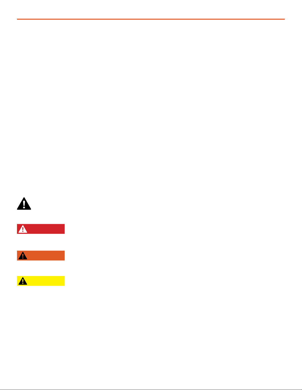
This is the safety alert symbol. This symbol is an alert to potential hazards that can cause
death or injury. All safety messages will follow the safety alert symbol and the word
“DANGER”, “WARNING”, or “CAUTION”. These words are dened as:
DANGER Indicates a hazardous situation which, if not avoided, will result in death or
serious injury.
WARNING Indicates a hazardous situation which, if not avoided, could result in death or
serious injury.
CAUTION Indicates a hazardous situation which, if not avoided, could result in minor or
moderate injury.
All safety messages will describe what the potential hazard is, how to reduce the chance of injury,
and what can happen if the instructions are not followed.
January 202010 |
System Setup and Operation Manual for HPS 500
Fire Hazard
Fire Types
Class A fire - Fires in ordinary combustibles such as wood, paper, cloth, trash, and plastics.
Class B fire - Fires in ammable liquids such as gasoline, petroleum, oil, and paint.
Class C fire - Fires involving energized electrical equipment such as motors, transformers, and
appliances. Remove the power source and the class C re becomes a class A or B re.
Recommended Fire Extinguisher
NSN 4210-00-288-7219 Fire Extinguisher, Carbon Dioxide, 10 lb
Carbon dioxide is a liqueed gas, which is highly effective ghting class B and C res. These
extinguishers are ideal for areas where contamination and/or cleanup are a concern, such as data
processing centers, labs, and telecommunication rooms.
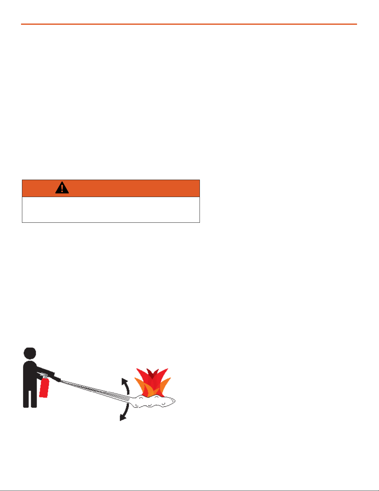
Using the Fire Extinguisher
When using the extinguisher on a re, remember PASS:
Pull the pin.
Aim the nozzle or hose at the base of the re from a safe distance.
Squeeze the operating lever to discharge the re extinguishing agent.
Sweep the nozzle or hose from side to side until the re is out. Move forward or around the re as
the re diminishes.
Watch the area for reignition until the cause has been xed.
Use Sweeping Motion
WARNING
Only CO2(carbon dioxide) re extinguishers should
be used with this equipment.
These additional cautionary steps will ensure
your safety:
• System components should not be operated in
standing water.
• Close and latch the component lids if it is
precipitating.
• System cables should not be routed through
standing water.
• Cable connections should remain dry.
• Unused ports on System components should
be covered when not in use to reduce the
possibility of water intrusion.

|11January 2020
System Setup and Operation Manual for HPS 500
PRO-Verter Grounding Lug
Figure 1. PRO-Verter grounding lug
Grounding the PRO-Verter at the grounding lug is an important
safety measure. The PRO-Verter and the generator (if included)
should be bonded to an earth grounding rod. When the
generator is running, the AC neutral and equipment ground
automatically are bonded internally at the generator. When
running off battery, the AC neutral and equipment ground are
automatically bonded internally at the PRO-Verter.
If the System is ever connected to grid power, the AC neutral
must be bonded to the earth ground at the main breaker panel
of the grid power. Any generator connected to the System must
have a neutral-to-ground bond.
Grounding the System
Electric Shock Hazard
WARNING
Standing water around the electrical equipment and/or intrusion of water into the System
components can increase the risk of electrical shock.
DON’T LET THIS BE YOU!
HIGH VOLTAGE: System components, PV
arrays, and generators may produce lethal
line voltages. Extreme care should be taken
to protect against electrocution. Always work
with another person in case an emergency
occurs. Disconnect power before performing
maintenance. Wear safety glasses whenever
working on any part of a system that requires
exposure to mechanical or direct electrical
contacts.
WARNING
The System is NOT GFCI protected.

January 202012 |
System Setup and Operation Manual for HPS 500
Environmental and Handling Precautions
All of the System components are ruggedized, yet there are a few things the operator can do to
prevent failures and prolong the operational life of the System.
Water
If outdoor operation is necessary, the lids
of all components should be closed and
latched. During operation, cases should be
placed upright, especially during inclement
weather. Lids should be open only to access
operator controls and closed at all other
times.
Impact
Equipment should not be dropped onto hard
surfaces at a height greater than one foot
when transporting or during operation.
Dust/Foreign Object Intrusion
Air intake lters should be cleaned once per
month, or more frequently when conditions
warrant. As a general rule, minimize exposure
to high levels of particulates and foreign
object debris by exercising common-sense
placement and protection during both
operation and storage.
Heat
Heat and solar loading reduces efciency and
life expectancy. Shade components (except
PV panels) to prevent the negative effects of
heat.

|13January 2020
System Setup and Operation Manual for HPS 500
THEORY OF OPERATION
The HPS 500 Architecture, Function and Operation
The HPS 500 System is designed as a fully independent power station, using renewable solar power
as its primary means of power generation.
The Power Hub, PRO-Verter and Expander Paks are designed to operate in concert, providing
uninterrupted pure sine wave 230V AC and 24V DC power to the loads. It is a powerful solution for
the following conditions:
1. Grid or Generator AC power sources are not present or only intermittently available.
2. Power requirements for the load may exceed an existing power source’s daily power output,
requiring multiple power sources to operate in concert to meet the demand.
3. The reduction of fuel-driven generator “run-time” is necessary, due to logistics concerns or to
simply to reduce the cost burdens of operating a generator.
It is important to follow two rules when conguring generation and storage technologies to serve in
an application:
1. The power generated over 24 hours must be greater than or equal to the power consumed
2. The energy storage capacity must be able to power the load over 24 hours (with no recharging)
The HPS 500 has a 12 kWh battery bank and ~2.1 kW photovoltaic (PV) array that operate in
concert to meet the daily power requirements.
Energy Storage – The Foundation of the HPS 500
Operating a generator has signicant cost burdens (logistics, support, etc). The HPS alleviates
those cost burdens by redirecting the nancial investment into a battery-based platform.
In the HPS 500, the energy storage modules (Expander Paks) serve as the “enabler” for the entire
HPS network. They enable all of the connected devices to operate in concert, with the PV array as
the primary means of power generation for the HPS.
Batteries in a hybrid system are designed to “cycle”. A full cycle is dened as one complete
discharge and recharge over a specic period of time. With every cycle that occurs, the HPS is
providing a return on the nancial investment.
Batteries have a cycle-life, and therefore should be considered the “consumable” part of the HPS.
The health of the battery can directly affect the function of the HPS over time, so proper cycling and
cell-health management practices are strongly encouraged. In any properly-sized Hybrid Power
System, the battery should cycle 1-2 times per day. See additional information about the Expander
Pak 1000 pages 89-93 of this Manual.

January 202014 |
System Setup and Operation Manual for HPS 500
Load Prioritization
When the HPS is fully functioning, providing power to the load is always prioritized over other functions.
When the PV arrays are generating in sunlight, that power is immediately directed to the load once it
ows into the HPS. The batteries will ONLY begin to charge once the PV generation exceeds the demand
from the load.
During periods of peak sunshine, PV power is exclusively used to support the load while excess energy
charges the batteries simultaneously. This function reduces the demand on the batteries, prolongs
battery-operation time, and promotes healthy cycling of the battery.
This same function also occurs when the HPS is connected to an AC source. If the HPS is connected to
an active generator or grid-utility, the load is always supported FIRST before any AC is used for charging
the HPS batteries. If the PRO-Verter is controlling a connected generator and the battery bank reaches a
low state-of-charge, the PRO-Verter can be programmed to auto-start the generator to keep AC owing
to the load, only charging the connected batteries once the load is fully supported by the generator.
The PRO-Verter and Power Hub are programmed at the factory for use in the solar-only HPS application.
It is possible to alter the programmed settings for changes in System conditions or application. Contact
your Field Service Representative.
Load Management
In the HPS 500, the PV arrays may be the only source of power generation available, and therefore, the
operator can reliably expect only one battery cycle per day. It is incumbent upon the operator to ensure
the load does not exceed the daily power generation of the PV arrays.
• During periods of inclement weather, HPS batteries may become depleted and fail to support the
load.
• If the load is too great for the PV arrays to fully and regularly recharge the batteries, the HPS may
experience interruptions in service.
Cycling the Expander Paks’ lead acid batteries in this manner will signicantly shorten their useful
lifespan. This situation may be improved by temporarily reducing or disconnecting the load, allowing the
batteries to charge fully.
If either of these conditions persist, the HPS architecture can be adjusted by adding power generation
and/or energy storage.
Scaling and Modifying the HPS 500
Both generation and energy storage can be scaled up or down as the load requirements change.
Additional generation sources should be selected based on availability of resources, logistics and the
environment (fuel-driven generator, wind, fuel cell, etc.)
Other capabilities can also be added or removed over time, including advanced power distribution
and management modules, stacking of generators with PRO-Verters, and more. Consult the
individual product manuals for additional information about scaling and stacking.

|15January 2020
System Setup and Operation Manual for HPS 500
Minimum Battery Capacity Required for Optimal PRO-Verter Operation
A Hybrid Power System will function most efciently when proper balance is achieved within the
System’s architecture (Energy Storage, Power Management, and Power Generation). The central
power management device is the PRO-Verter, so any components that are connected to it need to be
rated for the amount of power that will be processed by it.
For example, PRO-Verters can require extremely high current (amperage) from the batteries when AC
loads require power from the inverter, but it can also push high current into the battery when it is in
charge mode.
Each Expander Pak has a built-in circuit breaker that will trip at a value less than the maximum rated
current to/from the PRO-Verter. For this reason, multiple Expander Paks must be connected to a
PRO-Verter for the system to function at its rated power. The combined values of the Expander
Pak circuit breakers must be greater than the rated inverter/charger current required from the
PRO-Verter.
In the HPS, the PRO-Verter 5000 inverter can require up to 200 A from the batteries, and the charger
has a rated output of 110 A. Four (4) 24VDC Expander Pak 1000s is the MINIMUM number required
to support the inverter’s full inverter output, and be charged effectively and safely when the PRO-
Verter 5000 is in charge mode.
Connecting an insufcient number of Expander Paks (energy storage modules) to a PRO-Verter will
result in a situation where the batteries are charged or discharged too quickly:
• Charging lead-acid Expander Paks too quickly may result in an articially high battery voltage
reading and signal the PRO-Verter to turn off the generator before the batteries are actually
charged sufciently.
• Discharging Li Expander Paks too quickly may cause the battery temperature to rise to a point
that the Battery Management System (BMS) disconnects the batteries from the whole system.
Refer to the “Minimum Battery Capacity Recommendations” on the PRO-Verter I-Plate to ensure
trouble-free operation.

January 202016 |
System Setup and Operation Manual for HPS 500
“Overload” Conditions
Over-loading of the PRO-Verter can occur under the following conditions:
• Load AC power demand is greater than the inverter’s rated output
• Load AC power demand is greater than the connected AC source (generator or grid-utility)
• Load AC power demand is greater than the AC INPUT setting, which may cause the PRO-Verter
to disconnect from the AC source when in pass-through (charging) mode
• Load AC power demand is greater than the output of the connected AC source (generator or
grid utility) causing it to shut down
In each of these scenarios, the solution only requires a reduction in the Load AC demand. Use the
AC METERS to conrm the load is reduced to prescribed levels and proceed with normal operation.
Load Support
Load support (if equipped) is a function of the PRO-Verter that combines power from the external
AC source with the inverter AC output to support high AC loads that require more power than either
the PRO-verter or the AC source can provide individually.
It ONLY engages once the load exceeds the AC INPUT setting in the PRO-Verter, and because it
requires power from the batteries, it should only be used if the high loads are brief in duration and
intermittent.
In order for load support to function, the PRO-Verter must be connected to an active AC source.
Load support is an automatic function which will engage any time the AC load exceeds the AC
input power from a generator or grid source (controlled by the AC INPUT setting).
The PRO-Verter can also be congured to perform load support as a manual intervention method
when conditions warrant. Turning off CHARGE mode at the User Interface control is recommended.
Consult the I-Plate on the PRO-Verter to determine if the PRO-Verter is equipped with the load
support feature, and for the specic instructions on manual engagement of load support functions
for a particular application.
Lag Time and Surge Rates
The PRO-Verter’s inverter function can provide up to 130% of its rated power output for brief
surges that may be required to support a load. Most generators are also rated to support brief
surge loads. A PRO-Verter should be paired with an appropriately-rated generator, but if it is paired
with a smaller generator, the AC INPUT setting must be set to limit the AC power the PRO-Verter
will expect from the AC source. In this scenario, it is possible for the PRO-Verter to put up to 130%
load on the AC source (generator or grid-utility), which can occur when charging mode is engaged
and a sudden AC surge is demanded by the load. Since the PRO-Verter can’t determine in advance
how much power will be demanded at the time of the surge, it can only “react” to the surge
condition. It may take up to 1 full second for the PRO-Verter to react, and this period is known as
“Lag Time”. Lag time results in 130% of the AC INPUT setting being demanded from a generator
for up to 1 second.

|17January 2020
System Setup and Operation Manual for HPS 500
If the generator can’t handle 130% surge, it will likely crash the system in the following ways:
• The generator AC output voltage may drop below the VAC DROPOUT setting in the PRO-Verter
• The generator AC contactor (if present) or circuit breaker may open, causing a loss of AC at the
PRO-Verter
• If the generator has an electronic protection circuit, it may cause the until to shut down entirely.
All of these issues are resolved by dropping the AC INPUT setting so that it is less than 130% of the
output rating of the connected AC source.
Figure 2. Hybrid Power System in Operation

January 202018 |
System Setup and Operation Manual for HPS 500
System Operation Models
DC-only/Inverter
All power generated is from DC generators and AC loads are supported by the PRO-Verter’s Inverter
function using energy stored in batteries.
Hybrid
The “Continuous Load” AC power requirement is LESS than the individual Inverter or Generator/
Grid AC power output ratings.
The PRO-Verter serves as the primary power management device in a System, using either
Inverter AC or Generator/Grid AC power to maintain the load. In the HYBRID model, the batteries
will cycle regularly to mitigate generator run-time and logistical support often associated
with operation in remote locations. Hybrid systems also provide the operator with a exible
architecture that allows for the addition of multiple power sources, such as renewable power
generation.
• Allows critical durations of “silent” operation
• Allows renewable power generation when available
• Reduces generator burdens (fuel consumption, wet-stacking, maintenance, or logistic
support)
Load Support
The “Surge Load” AC requirement is MORE than the Generator/Grid AC power output, but less than
the Inverter AC power output rating.
The LOAD SUPPORT model allows the use of a smaller generator based on total loads operating
over 24-hour period rather than a larger generator required to support “peak” loads, which may
only last for a brief period. The PRO-Verter can be used to provide supplemental “surge” AC
power to a generator/grid AC power source during brief/intermittent periods while allowing the
“continuous” loads to be supported in the Hybrid model.
• Smaller generator = Less total System weight
• Promoted higher generator operating (motor) efciency
Peak Power Delivery
The “Peak Load” AC requirement is MORE than both the individual Inverter or Generator/Grid AC
output ratings.
If the load AC requirement exceeds the AC power output rating of both the individual inverter
and generator/grid, the PRO-Verter can combine the generator/grid AC power with the Inverter
AC power to supply “peak” AC power for brief periods.
• Decreases the need for larger generators supporting “peak” loads
UPS (Automatic Function)
A PRO-Verter connects critical AC loads directly to grid-utility or prime AC power when it is
available, and provides backup power for the load by supplying Inverter AC (using energy from a
connected battery bank) when the Grid-Utility or Prime AC source is interrupted.
• In the UPS model, “peak shaving” and the use of renewable power sources are also possible
by connecting a Power Hub.
|19January 2020
System Setup and Operation Manual for HPS 500
Component Stacking
When expanding or modifying the HPS architecture, stacking may be used to provide additional
capabilities that may exceed the ability of any one component to handle.
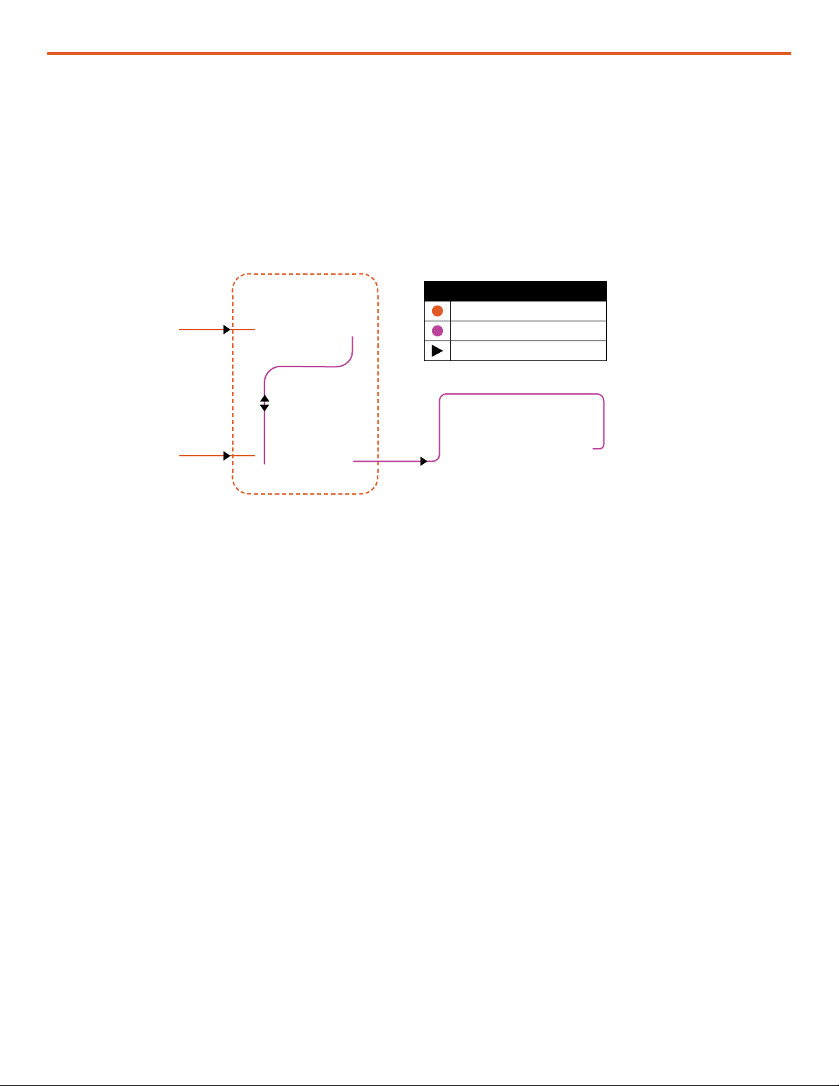
Power Hub Stacking
Stacking Power Hubs provides a mechanism to expand the capacity of a system, in a modular way,
to collect and store DC energy. The dashed-line box surrounds the stacked components in the gure
below.
PV Array (x6)
Power Hub 2500 Legend
DC Solar Circuit
Inter-Connect
direction of flow energy or comm
Figure 3. Example-Stacking Power Hubs
PV Array (x6) PRO-Verter
5000-220

January 202020 |
System Setup and Operation Manual for HPS 500
PRO-Verter Stacking
Stacking PRO-Verters, of the same or different types, provides a mechanism to power a wide variety
of AC loads from the same system. The dashed-line box surrounds the stacked PRO-Verters.
Figure 4. Example-Stacking PRO-Verters
PRO-Verter
7000-120 AGS
Inter-Connect Strip
Inter-Connect Strip
Communication Cable
Generator AC Power Cable
Li Expander Pak 2400
(x5)
Li Expander Pak 2400
(x5)
Legend
DC Solar Circuit
Inter-Connect
AC Load Circuit
AC Supply Power Cord
Communication Cable
direction of flow energy or comm
PRO-Verter
5000-220
120 VAC
Loads
220 VAC
Loads
Table of contents
Other Solar Stik Inverter manuals

Solar Stik
Solar Stik PSS-G Quick reference guide

Solar Stik
Solar Stik 16-0503201 User manual

Solar Stik
Solar Stik PRO-VERTER S 3000 User manual

Solar Stik
Solar Stik 24VDC POWER HUB 3500 Installation instructions

Solar Stik
Solar Stik 24VDC PRO-VERTER 7000-120 AGS Installation instructions

Solar Stik
Solar Stik PRO-VERTER 7000-120 User manual

Solar Stik
Solar Stik 11-1000020 Installation instructions

Solar Stik
Solar Stik ATSC MS3 L0 Manual instruction


