Heatit Controls Z-HAN B User guide
1. INTRODUCTION
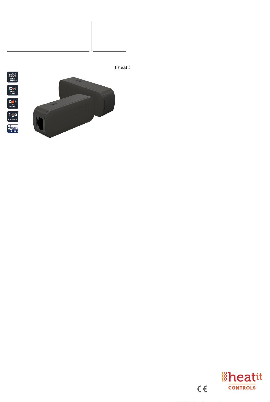
Heatit Z-HAN B is a Z-Wave™ HAN sensor for AMS meters (Smart
meters). The Heatit Z-HAN B works with Norwegian AMS meters.
Heatit Z-HAN B is equipped with an RJ45 port for connection to the
AMS meter. The Heatit Z-HAN B can be powered through the RJ45 port
by most AMS meters, but it also has a 5V micro USB port for external
power supply.
2. STATEMENT REGARDING PRODUCTS FROM MULTIPLE
MANUFACTURERS
Please read this before installation
This device may be used with all devices certified with the Z-Wave
Plus™ certificate and should be compatible with such devices
produced by any manufacturer. Every primary controller is different
depending on the manufacturer, their target audience and intended
use/application. Please review the functionalities implemented
by the primary controller you intend to use with our Z-Wave Plus
certified device to ensure that it provides the necessary controls to
take full advantage of our product’s capabilities.
3. BEHAVIOUR WITHIN THE ZWAVE™ NETWORK
This device may be operated within any Z-Wave network with
Z-Wave-certified devices from other manufacturers. All non-battery-
operated nodes within the network will act as repeaters regardless of
manufacturer to increase the reliability of the network. On delivery,
the device does not belong to any Z-Wave network. The device needs
to be added to an existing network to communicate with the other
devices within it. Devices may also be removed from a network. The
add/remove processes are initiated by the primary controller of the
Z-Wave network.
4. QUICK START
1. Contact your energy company to activate your HAN-port.
2. Connect power to the Z-HAN sensor with a micro USB cable.
3. Set the primary controller to add mode (security/non-security).
4. Press the reset button on the HAN sensor 3 times in a rapid
sequence. Heatit Z-HAN is now included in your Z-Wave network.
5. Open your main fuse box.
6. Plug the RJ45 cable into the Energy meter and the Z-HAN sensor.
HEATIT
ZHAN B Ver 2022-A
Firmware 1.0
01.11.2022
Installers manual
TABLE OF CONTENTS
1. Introduction
2. Statement regarding products from multiple manufacturers
3. Behaviour within the Z-Wave™ network
4. Quick Start
5. Add/Remove
5.1 Method 1: Standard (Manual)
5.2 Method 2: SmartStart (Automatic)
6. Factory Reset
7. Startup
8. LED blinking patterns description
9. QR-Code Placement (DSK)
10. Security
11. Node Information Frame
12. Associations
12.1 Setting and Removing Associations
13. Association Groups
14. Configuration Parameters
15. Command Classes
15.1 Meter Command Class
15.2 Indicator Command Class
16. Supported Command Classes
Product info
Art.no. 45 124 96

5. ADD/REMOVE
Please read this before installation
The primary controller/gateway has a mode for adding or removing
devices. Please refer to your primary controller manual on how to set
the primary controller in add/remove mode. The device may only be
added or removed from the network if the primary controller is in add/
remove mode. When the device is removed from the network, it will
NOT revert to factory settings.
An always listening node must be powered continuously and reside on
a fixed position in the installation to secure the routing table. Adding the
device within a 2m range from the gateway can minimize faults during
the Interview process.
There are two ways to add the device to a Z-Wave network.
5.1 Method 1: Standard (Manual)
Add/remove mode is indicated on the device by a blinking green LED.
It indicates this for 90 seconds until a timeout occurs, or until the
module has been added to/removed from the network.
To start the configuration process, press the reset button 3 times in
rapid succession. The LED will light up in green for 3 seconds if adding/
removing is successful. The device is now ready for use with default
settings.
NB! When the device is removed from the gateway, the parameters are
not reset. To reset the parameters, see Chapter 6 ”Factory reset”.
If inclusion fails, please perform a ”remove device” process and try
again. If inclusion fails again, please see Chapter 6 “Factory reset”.
5.2 Method 2: SmartStart (Automatic)
SmartStart enabled products may be added to a Z-Wave network
by scanning the Z-Wave QR-Code on the product if your primary
controller supports SmartStart inclusion. No further action is required
and the SmartStart product will be added automatically after being
powered on within range of the primary controller.
6. FACTORY RESET
Press and hold the reset button. After 3 seconds the LED will start to
blink in green. After 20 seconds the LED will shine solid green for 3
seconds. You may now release the button.
Please use this procedure only when the network primary controller is
missing or otherwise inoperable.
7. STARTUP
After powering up the device for the first time, all the parameters will
have default settings.
8. LED BLINKING PATTERNS DESCRIPTION
The device supports numerous LED blinking patterns to make it as
easy as possible to identify what the device is doing.
Device Not in Network
The LED will flash in red when the
device is not added to a Z-Wave
network
Add/Remove
When device enters add/remove
mode the LED will flash green.
If successful, the LED will light up in
green for 3 seconds.
If unsuccessful, the LED will light up in
red for 3 seconds.
Communication
The device should blink green every
time it sends data over Z-Wave
Factory Reset
If the button is pressed for more than
3 seconds, the GREEN LED will start
flashing.
When the button has been pressed
for 20 seconds, the GREEN LED will
light up for 3 seconds.
Figure 1 (success)
Within the 3 second period the but-
ton must be released. If the button is
released within this period, the device
will reset and start flashing because it
is not included in a gateway.
Figure 2 (fail)
If the button is released before the
3 second period, the device will
indicate fail by turning RED LED on for
3 seconds.
Figure 3 (fail)
The button MUST be released
between 20 and 23 seconds for local
reset to take place. If held longer, the
device will ignore the command.
9. QRCODE PLACEMENT DSK
The QR-Code is needed when including a device using S2 security or
SmartStart. The DSK can be found in the QR-Code and is located;
• On the product.
• On the Quick Guide.
• On the gift box.
0s 1s 2s 3s
Z-Wave Data transmission indication
4s 5s
Figure 1
Figure 2
Figure 3

14. CONFIGURATION PARAMETERS
Z-Wave products are supposed to work out of the box after inclusion.
Some device configuration may, however, alter the functionality to better
serve user needs or unlock further enhanced features. All the parameters
except 9 and 10 do not feature altering capabilities, advances or read
only flag. Parameter 9 and 10 are only read parameters.
PARA NO
PARA SIZE
NAME
SHORT
DESCRIPTION /
COMMENT
MINIMUM
MAXIMUM
DEFAULT
DESCRIPTION
OF VALUE
1 4 Meter report
hysteresis
for W.
Set the Meter
Report hysteresis
for Watts.
0 100 000 200 0 = Disabled.
1 - 100 000W.
Default 200W.
2 2 Meter report
hysteresis
for V.
Set the Meter
Report hysteresis
for Volts.
0 420 5 0 = Disabled.
1 - 420V.
Default 5V.
3 2 Meter report
hysteresis
for A.
Set the Meter
Report hysteresis
for Amps.
0 65 535 20 0 = Disabled
1 - 65 535A
(0.1 - 6553.5A)
Default 20 (2A).
4 2 Meter report
interval
for W.
Time Interval
between
consecutive W
reports.
10 65 535 10 10 - 65 535 seconds.
Default 10 seconds.
5 2 Meter report
interval for
V and A.
Time interval
between
consecutive
meter reports.
This parameter
will issue: V and A.
10 65 535 300 10 - 65 535 seconds.
Default 300 seconds
(5 minutes).
6 2 Temperature
report
interval.
Time interval
between
consecutive
temperature
reports.
30 65 535 300 30 - 65 535 seconds.
Default 300 seconds
(5 minutes).
7 1 Temperature
report
hysteresis.
Temperature
reports based
on change in
temperature from
last report.
NB!
0.5°C increments.
0 100 10 0 = Disabled.
1-100
(0.1-10.0°C).
Default 10 (1°C).
NB! This para-
meter has 0.5°C
increments.
8 1 Sensor
calibration.
Manually
calibrates the
sensor ±6°C.
-60 60 0 -6.0°C to 6.0°C.
Calibrates the
sensor by ±6°C.
NB! To set a
negative value,
use 256 and
subtract the
desired value.
9 4 Serial First half of the
meter point serial
number.
Read only
0 4 294.9
67 295
1 718
972 025
Shows the first half
of the meter point
serial number.
NB! This para-
meter is read only.
10 4 Number Last half of the
meter point serial
number.
Read only
0 4 294.9
67 295
1 835
363 685
Shows the last half
of the meter point
serial number.
NB! This para-
meter is read only.
15. COMMAND CLASSES
Besides the mandatory command classes, the device has support for
the following command classes:
15.1 Meter Command Class
The device supports Meter Command Class Get, and the Z-HAN sensor
will only respond on supported electric meter scales:
kWh (accumulated), W (power), V (voltage) and A (current).
The device will report when asked:
Rate import: Import (0x01)
Meter type: Electric meter (0x01)
Precision: 1 decimal (0x01)
10. SECURITY
S2 security enhances Z-Wave Plus with an additional layer of AES
128-bit encryption of the wireless Z-Wave communication to prevent
hacking and man-in-middle attacks on the home network. This device
supports S2 and has a Z-Wave DSK QR-Code label that may be used
when the module is added to the Z-Wave home network. The primary
controller will ask for a 5-digit code, which can be found underneath
the QR-Code.
11. NODE INFORMATION FRAME
The node information frame is the ”business card”of a Z-Wave device.
It contains information about the device type and its technical features.
The add and remove procedure of the device is confirmed by sending
out a node information frame. Besides this, it may be necessary for
certain network operations to send out a node information frame.
12. ASSOCIATIONS
Z-Wave devices interact with other Z-Wave devices. The relationship
between one device controlling another device is called an association.
In order to control a subordinate device, the controlling device needs
to maintain a list of devices that will receive controlling commands.
These lists are called ”Association Groups”. They are always related to
the specific event triggered (e.g., sensor reports). In case the event is
triggered, all devices stored in the respective association group will
receive a joint wireless command.
12.1 Setting and Removing Associations
Associations may be assigned and removed via Z-Wave commands.
Please refer to your primary controller/Z-Wave gateway for more
information.
13. ASSOCIATION GROUPS
MULTI LEVEL SWITCH DEVICE DESCRIPTION
Group 1
Lifeline
Lifeline. (Normally used by the Z-Wave Controller) Sends:
- Device Reset Notification
- Indicator Report
- Meter Report
- Multilevel Sensor
Max nodes in group: 5
Group 2
Meter report
- Meter report (kWh)
- Meter report (W)
Max nodes in group: 5
PRODUCT INFO Heatit Z-HAN B
FEATURES
• Z-Wave HAN sensor
• RJ45 and Micro-USB
• Power metering
• SmartStart
• Firmware update (OTA)
• Temperature sensor
• Supports encryption mode S0, S2 Authenticated Class,
S2 Unauthenticated Class
The product must be used with a security-enabled Z-Wave
Controller in order to fully utilize security/encryption.
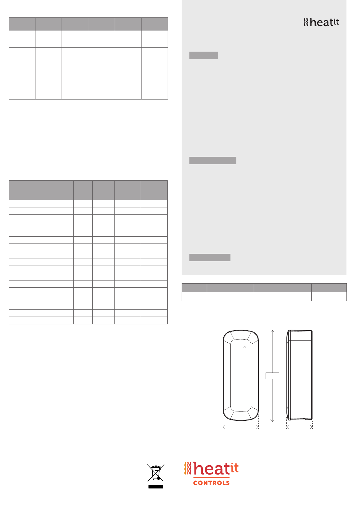
TECHNICAL DATA
Protocol Z-Wave, 868.4MHz
Chip Z-Wave 700 chip
Rated voltage 5V DC
Ambient temperature 5°C to 40°C
Humidity 10% to 85% RH
Range RF Min. 40 meter
IP Code IP 20
Size (LxWxH) 80 x 31 x 22mm
Approvals Z-Wave Plus v2, CE
MAINTENANCE
The device is maintenance-free. Only for indoor installation.
ART. NO. PRODUCT COLOR FREQUENCY
45 124 96 Heatit Z-HAN B Black Olive RAL 6015 EU 868.4MHz
TYPE SCALE VALUE SIZE PRECISION
REPORT
HYSTERESIS
Electric kWh 0x00 4 2 On change
from AMS
meter.
Electric W 0x02 4 0 200W / 10s,
configurable
by parameter.
Electric V 0x04 2 1 5V / 300s,
configurable
by parameter.
Electric A 0x05 2 1 2A / 300s,
configurable
by parameter.
15.2 Indicator Command Class
The device supports Indicator Command Class.
The indicator Command Class will turn ON/OFF internal LED.
16. SUPPORTED COMMAND CLASSES
The following table lists all Command Classes supported by the Z-Wave
device. The device supports S0, S2 Authenticated security and
S2 Unauthenticated security.
ASSOCIATION VERSION
INSECURE
INCLUSION
INSECURE ON
SECURE
INCLUSION
SECURE ON
SECURE
INCLUSION
Association Group Information V3 Yes Yes
Device Reset Locally V1 Yes Yes
Firmware Update Meta Data V5 Yes Yes
Indicator V3 Yes Yes
Manufacturer Specific V2 Yes Yes
Multi Channel Association V3 Yes Yes
Powerlevel V1 Yes Yes
Security V1 Yes Yes
Security 2 V1 Yes Yes
Supervision V1 Yes Yes
Transport Service V2 Yes Yes
Version V3 Yes Yes
Z-Wave Plus Info V2 Yes Yes
Meter V5 Yes Yes
Configuration V4 Yes Yes
Multilevel Sensor V11 Yes Yes
Association V2 Yes Yes
80mm
31mm 22mm
Heatit Controls AB l Läkarvägen 4, 454 31 BRASTAD, SWEDEN
Heatit Controls AB can not be held liable for typographical errors, other errors or omittances in our information.
Product specifications may change without further notice. All electrical installations must be carried out by a licensed
electrician. The product must be installed in accordance with national building codes and our installers manual.
DISPOSAL GUIDELINES
Do not dispose of electrical appliances as unsorted municipal waste, use separate collection
facilities. Contact your local government for information regarding the collection systems
available. If electrical appliances are disposed of in landfills or dumps, hazardous substances
can leak into the groundwater and get into the food chain, damaging health and well-being.
This manual suits for next models
1
Other Heatit Controls Accessories manuals


