Heatit Controls Z-TRM6 User manual

1. INTRODUCTION
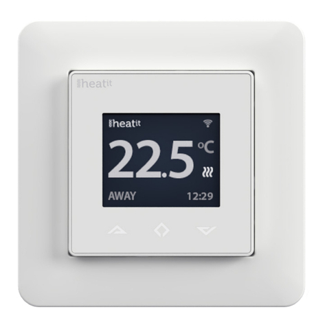
Heatit Z-TRM6 is an electronic thermostat designed for
electrical heating. The thermostat can be controlled through
your Z-Wave™ network or via the buttons on the front. The
thermostat has a user friendly interface.
Heatit Z-TRM6 has 3 modes; Heat - Cool and Eco.
The thermostat fits in standard European junction boxes and
may be used with most System 55 frames. It has a sturdy metal
frame for secure fastening on the junction box. The thermostat
has one built-in room temperature sensor. Two additional
external temperature sensors may also be connected.
Heatit Z-TRM6 has active power metering and it gives you
real time information about your power consumption. It also
allows you to set the power metering value manually in case
of connection with a contactor.
The device has implemented ZeroX technology. This
technology makes sure the relay switches at 0V when turning
on and o. With this technology the thermostat will have a
much longer lifetime.
The thermostat can be set up with multiple associations and
can be used as a master thermostat. It can control up to 10
thermostats and 10 external relays E.g wall plugs.
The thermostat can withstand a load of max 16A/3600W at
230VAC. We recommend a contactor for loads above 13A.
2. STATEMENT REGARDING PRODUCTS FROM MULTIPLE
MANUFACTURERS
Please read this before installation
This device may be used with all devices certified with the
Z-Wave Plus™ certificate and should be compatible with
such devices produced by any manufacturer. Every primary
controller is dierent depending on the manufacturer, their
target audience and intended use/application. Please review
the functionalities implemented by the primary controller you
intend to use with our Z-Wave Plus certified device to ensure
that it provides the necessary controls to take full advantage of
our product’s capabilities.
3. BEHAVIOR WITHIN THE Z-WAVE NETWORK
This device may be operated within any Z-Wave™ network
with Z-Wave-certified devices from other manufacturers. All
non-battery-operated nodes within the network will act as
repeaters regardless of manufacturer to increase the reliability
of the network. On delivery, the device does not belong to any
Z-Wave network. The device needs to be added to an existing
network to communicate with the other devices within it.
Devices may also be removed from a network. The add/
remove processes are initiated by the primary controller of the
Z-Wave network.
PRODUCT
DOCUMENTS
HEATIT
Z-TRM6
Installers manual
Firmware version Document version
FW 1.0 2023-B
Article no. Document date
54 305 66
54 305 67
54 305 68
01.09.2023
Org. doc. date 01.07.2023
White RAL 9003 White RAL 9010
54 305 66 54 305 67
TABLE OF CONTENTS
1. Introduction
2. Statement regarding
products from multiple
manufacturers
3. Behavior within the
Z-Wave network
4. Quick Start
5. Installation
6. Connections
7. Add/Remove
8. Factory reset
9. Startup
10. Principles of regulation
11. Local settings menu
12. Display menu structure
13. Temperature shown in
display
14. Standby and main screen
15. KWh value in menu
16. Size of load
17. Choice of sensor
18. Selecting sensor value
19. Calibration
20. Brightness
21. Display on/o
22. Display icons
23. Child lock
24. Open window detection
25. Error codes
26. Safety features
27. QR-Code placement (DSK)
28. Security
29. Node Information Frame
30. Associations
31. Association Groups
32. Configuration Parameters
33. Command Classes
34. Supported Command
Classes
35. Controlled Command
Classes
36. Thermostat dimensions
37. Chart - Display menu
structure
Product info
Black matt
54 305 68

4. QUICK START
1. Switch o the mains voltage (disable the fuse).
2. Open the junction box.
3. Connect the wires according to the description in
Chapter 6; ”Connections”. Optional: Connect external wired
sensors.
4. After verifying the connections, switch on the mains voltage.
5. Set the primary controller in add mode (security/non-
security).
6. Hold the Center button until “OFF” is shown in the display
(approx. 5 seconds).
7. Press the ”+” button once to reach “CON”, and hold until the
display shows a rotating light pattern.
8. The thermostat will display “INCL” when the thermostat is
successfully added. NB! If adding/removing fails, Err (error)
will appear.
5. INSTALLATION
Installation must be done by a qualified electrician in
accordance with national building codes. Before installation,
disconnect the power to the device from the mains. During
installation of the device, power to the device must be
disconnected AT ALL TIMES!
The product allows for wiring of cables with a cross section of
up to 1x2.5mm.
6. CONNECTIONS
Max tightening torque for terminal screws: 2Nm.
If the cable used has multiple strands using a end sleeve is
advised.
To access the terminal screws, hold the sides of the display
and gently pull outwards to detach the front piece.
Floor sensor NTC type 6.8, 10, 12, 15, 22, 33, 47 or 100kΩ.
Default 10kΩ.
External sensor NTC type 6.8, 10, 12, 15, 22, 33, 47 or 100kΩ.
Default 10kΩ.
NPower connection (Neutral) 230VAC.
Heating N Heating cable N connection.
LPower connection (Live) 230VAC.
Heating L Heating cable L connection.
Next, position the thermostat and mount it into the junction
box using 2 screws. Position the thermostat front over the part
mounted in the junction box, then carefully press the front
until it clicks into place. In order to get power metering values,
the load needs to be connected to both heating L + N.
7. ADD/REMOVE
Please read this before installation
The primary controller/gateway has a mode for adding or
removing devices. Please refer to your primary controller
manual on how to set the primary controller in add/remove
mode. The device may only be added or removed from the
network if the primary controller is in add/remove mode.
When the device is removed from the network, it will NOT
revert to factory settings.
An always listening node must be powered continuously
and reside in a fixed position in the installation to secure the
routing table. Adding the device within a 2 meter range from
the gateway can minimize faults during the Interview process.
There are two ways to add the device to a Z-Wave network.
7.1 Method 1: Standard (Manual)
Add/remove mode is indicated on the device by rotating
LED segments on the display. It indicates this for 90 seconds
until a timeout occurs, or until the device has been added to/
removed from the network. Configuration mode can also be
cancelled by performing the same procedure used for starting
Configuration mode.
1. Hold the Center button for 5 seconds.
The display will show “OFF”.
2. Press the ”+” button once to see “CON” in the display.
3. Start the add/remove device process in your primary
controller.
4. Start the configuration mode on the thermostat by holding
the Center button for approximately 2 seconds.
The device is now ready for use with default settings.
NB! When the device is removed from the gateway, the
parameters are not reset. To reset the parameters, see Chapter
”Factory reset”.
If inclusion fails, please perform a ”remove device” process and
try again. If inclusion fails again, please see “Factory reset”.
7.2 Method 2: SmartStart (Automatic)
SmartStart enabled products may be added to a Z-Wave
network by scanning the Z-Wave QR-Code on the product
if your primary controller supports SmartStart inclusion. No
further action is required and the SmartStart product will be
added automatically after being powered on within range of
the primary controller.
8. FACTORY RESET
Enter the menu by holding the Center button for about 5
seconds, navigate in the menu with the ”+” button til you see
FACT. Press the Center button until you see “-- --” blinking in
the display, then hold for about 5 seconds to perform a reset.
You may also initiate a reset by holding the Right and Center
buttons for 60 seconds.
When either of these procedures has been performed, the
thermostat will perform a complete factory reset. The device
will display “RES” for 5 seconds while performing a factory
reset. When “RES” is no longer displayed, the thermostat has
been reset.
Please use this procedure only when the primary controller is
missing or otherwise inoperable.

By pressing any button once, you will see the measured
temperature. By pressing the Left or Right button multiple
times, you will change the setpoint.
15. KWH VALUE IN MENU
The device supports power metering to give insight into the
power consumption of the heating. The total consumption of
the device can be seen in the system from the “kWh” menu
option. The total consumption data can be reset by holding
the Center button while in the kWh menu.
16. SIZE OF LOAD
In the “load” menu or from Parameter 29 (size of load), the
load value can be set manually if the load is not directly
connected to the thermostat. The size of load can be adjusted
in 100W increments up to 9900W.
17. CHOICE OF SENSOR
The thermostat has multiple sensors and sensor modes. This
lets you configure the thermostat to work correctly in most
installations. The sensors and modes may be selected from
either the local settings menu or via Parameter 2; ”Sensor
mode (“OPER”)”.
Available sensor modes:
FFloor sensor
AInternal room sensor
AF Internal room sensor + Floor sensor
A2 External room sensor
A2F External room sensor + Floor sensor
PWER Power regulator mode (no sensor used)
NOTE: Some types of floor require that a floor sensor
is connected in order to limit the floor temperature to
a maximum of 27°C (check the manual from the floor
manufacturer). When the thermostat is used in (AF or A2F) the
floor limiter FHI is automatically set to 27°C. When using any
other sensor type (A, F or A2) the minimum and maximum
limits are 5°C and 40°C respectively.
18. SELECTING SENSOR VALUE
The thermostat allows the selection of multiple dierent
resistance values of an NTC sensor and can be selected using
either the local settings menu or via Parameter 3: ”Sensor value
“SEN”. The supported sensor values are as follows:
6.8, 10, 12, 15, 22, 33, 47 or 100KΩ.
The factory default value is 10kΩ. When connecting both the
floor sensor and the external sensor, make sure to use sensors
with the same Ohm value.
19. CALIBRATION
If the temperature sensor readout is not correct, you can make
minor changes to the temperature readout. The temperature
readings can be calibrated by ±6°C using Parameter 10, 11
and 12. The calibration can also be performed from the menu
using CAR, CAE and CAF. The adjusted value will be displayed
in the controller/gateway indicating what the thermostat uses
for regulation.
9. STARTUP
After powering up the device for the first time, all parameters
will have default settings and the thermostat will start by asking
which sensor mode should be used.
10.PRINCIPLES OF REGULATION
The thermostat uses temperature readings retrieved from the
internal sensor and/or from external wired sensors to regulate
the temperature. The thermostat will regulate the temperature
using hysteresis or PWM, based on the setpoint temperature.
To select either “HYST” or “PWM” you can find the “REG” menu
option or use Parameter 13 “Regulation mode (“OPER”)”.
10.1 Hysteresis
Hysteresis will turn on and o the load based on the hysteresis
value in comparison to the setpoint. You can make changes
to the thermostat hysteresis. You may choose hysteresis
values between 0.3°C and 3.0°C using Parameter 14. The
default setting is 0.5°C. When using waterbased heating we
recommend a hysteresis of 1.0°C.
You may also change the hysteresis by entering the local
settings menu and holding the Center button for 2 seconds
when “REG” is displayed. Here you can choose values
between 0.3 and 3.0.
10.2 Pulse-width modulation PWM
With PWM regulation enabled, the thermostat will regulate
based on duty cycles. The thermostat is turned on and o in
percentage intervals of the cycle. The amount of time the relay
will be on is based on how far the measured temperature is
from the setpoint.
11. LOCAL SETTINGS MENU
To enter the settings menu, hold the Center button for 5
seconds. The display will display “OFF”. You are now in the
settings menu. While in the settings menu, “SET” will be
displayed in the bottom right of the display. You can now scroll
up and down using the Left and Right buttons. Some options
have submenus. To navigate the submenus, press the Center
button once to enter or exit the submenu. Press the Left and
Right buttons to find your desired value and hold the Center
button for 2 seconds to confirm your selection. “STOR” will
appear to indicate settings are stored.
12. DISPLAY MENU STRUCTURE
See flowchart at the end of this manual.
13. TEMPERATURE SHOWN IN DISPLAY
By default, the temperature shown on the display while
in standby state is the setpoint. This may be altered with
Parameter 15:”Temperature display”. It may also be changed
by entering the local settings menu and holding the Center
button for 2 seconds when “MODE” is displayed. You can
choose between “SETT” and “RELT”. “SETT” is the Setpoint
temperature and “RELT” is the real-time temperature.
14.STANDBY AND MAIN SCREEN
When the thermostat remains untouched for a while, it will
automatically go to the standby screen. The standby will by
default show the setpoint temperature.

SENSOR TYPE IN MENU STRUCTURE PARAMETER
Internal sensor CAR 10
External sensor CAE 11
Floor sensor CAF 12
20.BRIGHTNESS
Using the menu choices “BR1” and “BR2”, the brightness
of the display in Active and Standby state can be changed
respectively. “BR1” and “BR2” are also included in the device as
Parameter 16 (BR1) and Parameter 17 (BR2).
21. DISPLAY ON/OFF (DON/DOFF)
The thermostat has a display ON/OFF function which decides
whether the display should turn completely o when in
Standby. To enable/disable this function, hold the Left and
Center buttons for 10 seconds. The display will show “DOFF”
when the function is activated and “DON” when the function is
disabled. When operating any button, the display will light up.
22.DISPLAY ICONS
ICON DESCRIPTION
This icon will be displayed while the relay is on and the
thermostat is in either Heating or Eco mode.
This icon will be displayed while the relay is on and the
thermostat is in Cooling mode.
This icon shows the current signal strength.
23. CHILD LOCK
Child lock is a function for disabling the buttons from the
display locally. It will show “LOCK” when attempting to
operate it while the function is enabled. To enable or disable
the function, hold the Left and Right buttons for 10 seconds.
Enabling the function will show “LOCK” in the display, disabling
the function will show “OPEN”.
24.OPEN WINDOW DETECTION OWD
Open Window Detection (OWD) is a function which will
reduce the thermostat setpoint on detection of an open
window. This happens when the temperature sensor registers
a rapid temperature drop.
When OWD is active, the setpoint is reduced to 5°C in order
not to waste energy. OWD will automatically be cancelled
if OWD has been active for more than 1 hour, or if the
temperature increases by 3°C. OWD can also be cancelled
manually by increasing/decreasing the setpoint with the Left
and Right buttons.
By default, OWD is not enabled. The feature may be enabled
by selecting “OWD” from the menu. Choose between options
“OFF” and “ON”. It can also be enabled by setting parameter 26
(open window detection) to 1.
25. ERROR CODES
Err Adding fail. See Chapter 7 “Add/remove”.
Err1 Internal error. Most probably a faulty unit. Replace unit.
Err2 Z-Wave error. Most probably a faulty unit. Replace unit.
Err3 Internal error. Most probably a faulty unit. Replace unit.
Err4 Floor sensor error. You have chosen F, AF or A2F sensor
mode without having a floor sensor connected, or the
sensor may be damaged.
Err5 External sensor error. You have chosen A2 or A2F sensor
mode without having an external sensor connected, or
the sensor may be damaged.
Err6 Overheating. Contact your electrician.
Err7 Overload. Contact your electrician.
26.SAFETY FEATURES
The device has safety features to ensure safe operation and
warn the user of any faults/unexpected behavior. The device
has an Overheat and Overload function. If the thermostat
registers an Overheat or Overload incident, the thermostat will
switch o and an error will appear in the display.
26.1 Overheating
The device features internal temperature sensors that
detect overheating. It warns the user and turns o the relay to
prevent any damage.
When overheating is detected, the device will:
• Turn o the relay.
• Display Err6 in the display.
• Send a notification to the gateway.
26.2 Overload
The device features a 16A overload protection. The overload is
triggered if there is a current draw of more than 16A.
When overload is detected, the device will:
• Turn o the relay.
• Display Err7 in the display.
• Send a notification to the gateway.
26.3 Sensor failure
The device has the ability to detect when there is no sensor
connected or the sensor is broken or otherwise defective,
causing an open circuit.
When the device detects the sensor error, the device will:
• Turn o the relay.
• Display an error in the display, changes based on which
sensor is not connected/faulty.
To clear the “Sensor not connected” error the device has to
be disconnected from the mains, and the wiring and sensor(s)
need to be checked. When the fault is resolved the mains can
be reconnected and the device will function normally again.
27. QR-CODE PLACEMENT (DSK)
The QR-Code is needed when including a device using S2
security or SmartStart. The DSK can be found in the QR-Code
and is located;
• On the product.
• In the Quick Guide.
• On the packaging box/gift box.
28.SECURITY
S2 security enhances Z-Wave Plus with an additional layer of
AES 128-bit encryption of the wireless Z-Wave communication
to prevent hacking and man-in-middle attacks on the home
network.

This device supports S2 and has a Z-Wave DSK QR-Code label
that may be used when the device is added to the Z-Wave
home network. The primary controller will ask for a 5-digit
code. They are the first underlined 5 digits located on the
QR code sticker. The primary controller will then ask you to
confirm the rest of the code that is contained in the QR-Code.
29.NODE INFORMATION FRAME
The node information frame is the ”business card” of a Z-Wave
device. It contains information about the device type and
its technical features. The add and remove procedure of
the device is confirmed by sending out a node information
frame. Besides this, it may be necessary for certain network
operations to send out a node information frame.
30.ASSOCIATIONS
Z-Wave devices interact with other Z-Wave devices. The
relationship between one device controlling another device is
called an association. In order to control a subordinate device,
the controlling device needs to maintain a list of devices that
will receive controlling commands. These lists are called
”Association Groups”. They are always related to the specific
event triggered (e.g., sensor reports). In case the event is
triggered, all devices stored in the respective association group
will receive a joint wireless command.
30.1 Setting and Removing Associations
Associations may be assigned and removed via Z-Wave
commands. Please refer to your primary controller/Z-Wave
gateway for more information.
30.2 Multi Channel support
Heatit Z-TRM6 has support for the Multi Channel Command
Class. This allows the thermostat to be perceived as multiple
devices by the primary controller, which enables the reporting
of multiple temperature sensors and the ability to distinguish
between the reports coming from the device.
30.3 No Multi Channel support
If the primary controller or the Z-Wave devices to be
associated with Heatit Z-TRM6 do not support the Multi
Channel Association Command Class (Multi Channel
encapsulation), only the association groups in the root device
are accessible. This device contains 3 association groups in
addition to the Lifeline Group.
31. ASSOCIATION GROUPS
Without Multi Channel support:
MULTI LEVEL SWITCH DEVICE DESCRIPTION
Group 1
Lifeline.
Lifeline Group to be used by primary controller, sends:
-Thermostat Mode Report
-Thermostat Setpoint Report
-Thermostat Operating State Report
-Protection Report
-Notification Report
-Meter Report
-Sensor Multilevel Report
-Device Reset Locally Notification
-Indicator Report
-Configuration Report
Max nodes in group: 1
Group 2
Binary Switch Set.
Send Binary Switch set commands based on the internal relay state, sends:
-Binary Switch Set
Max nodes in group: 10
MULTI LEVEL SWITCH DEVICE DESCRIPTION
Group 3
Thermostat Setpoint set.
Sends Thermostat Setpoint set commands based on own setpoint to allow for
use as master thermostat, sends:
-Thermostat Setpoint Set
Max nodes in group: 10
Group 4
Thermostat Mode set.
Sends Thermostat Mode set commands based on own mode to allow for use as
master thermostat, sends:
-Thermostat Mode Set
Max nodes in group: 10
With Multi Channel support:
1: THERMOSTAT DEVICE THE MAIN THERMOSTAT DEVICE
Group 1
Lifeline.
Lifeline Group to be used by primary controller, sends:
-Thermostat Mode Report
-Thermostat Setpoint Report
-Thermostat Operating State Report
-Protection Report
-Notification Report
-Meter Report
-Sensor Multilevel Report
-Device Reset Locally Notification
-Indicator Report
-Configuration Report
Max nodes in group: 1
Group 2
Binary Switch Set
Send Binary Switch set commands based on the internal relay state, sends:
-Binary Switch Set
Max. nodes in group: 10
Group 3
Thermostat Setpoint Set
Sends Thermostat Setpoint set commands based on own setpoint to allow for
use as master thermostat, sends:
-Thermostat Setpoint Set
Max. nodes in group: 10
Group 4
Thermostat Mode Set.
Sends Thermostat Mode set commands based on own mode to allow for use as
master thermostat, sends:
-Thermostat Mode Set
Max. nodes in group: 10
2: MULTILEVEL SENSOR DEVICE INTERNAL SENSOR
Group 1
Lifeline.
Lifeline Group for internal sensor, sends:
-Sensor Multilevel Report
Max. nodes in group: 0
3: MULTILEVEL SENSOR DEVICE EXTERNAL SENSOR
Group 1
Lifeline.
Lifeline Group for external sensor, sends:
-Sensor Multilevel Report
Max. nodes in group: 0
4: MULTILEVEL SENSOR DEVICE FLOOR SENSOR
Group 1
Lifeline.
Lifeline Group for floor sensor, sends:
-Sensor Multilevel Report
Max. nodes in group: 0
32. CONFIGURATION PARAMETERS
Z-Wave products are supposed to work out of the box after
inclusion. Some device configuration may, however, alter
the functionality to better serve user needs or unlock further
enhanced features. All the parameters below do not feature
altering capabilities, advanced or read only flags.
PARA NO#
PARA SIZE
(BYTE)
NAME
SHORT
DESCRIPTION / COMMENT
MIN
MAX
DEFAULT
DESCRIPTION
OF VALUE
1 1 Disable
buttons
Disable buttons, must be en-
abled through the parameter,
or turned back on locally by
holding the center and right
button for 30 seconds until the
display shows “UNLK”.
0
0
Enabled, buttons on the
front of the device work.
(Default)
1
Disabled, buttons on the
front of the device are
disabled.
2 1
Sensor
mode
(OPER)
Choose which sensors the
thermostat should use for
regulation.
0
1
F, Floor sensor
1 A, Internal sensor (Default)
2AF, Internal sensor with
floor sensor limitations
3 A2, External sensor
4A2F, External sensor with
floor sensor limitations
5PWER, Power regulator
mode

PARA NO#
PARA SIZE
(BYTE)
NAME
SHORT
DESCRIPTION / COMMENT
MIN
MAX
DEFAULT
DESCRIPTION
OF VALUE
3 1 Sensor
value (SEN)
Select the resistance value of
the connected NTC.
0
0
10KΩ(Default)
1 12KΩ
2 15KΩ
3 22KΩ
4 33KΩ
5 47KΩ
6 6.8KΩ
7 100KΩ
4 2
Internal
sensor min
temp limit
Decides the lowest tempera-
ture allowed by the thermostat
when using sensor mode A.
50 400 50 5°C to 40°C (Default is 5°C)
5 2
Floor
sensor min
temp limit
Devices the lowest tempera-
ture allowed by the thermostat
when using sensor mode
AF, F, A2F.
50 400 50 5°C to 40°C (Default is 5°C)
6 2
External
sensor min
temp limit
Decides the lowest tempera-
ture allowed by the thermostat
when using sensor mode
A2, A2F.
50 400 50 5°C to 40°C (Default is 5°C)
7 2
Internal
sensor max
temp limit
Decide the highest tempera-
ture allowed by the thermostat
when using sensor mode A.
50 400 400 5°C to 40°C
(Default is 40°C)
8 2
Floor
sensor max
temp limit
Decide the highest tempera-
ture allowed by the thermostat
when using sensor mode
AF, F, A2F.
50 400 400 5°C to 40°C
(Default is 40°C)
9 2
External
sensor max
temp limit
Decide the highest tempera-
ture allowed by the thermostat
when using sensor mode
A2, A2F.
50 400 400 5°C to 40°C
(Default is 40°C)
10 1
Internal
sensor
calibration
(CAR)
Manually calibrate sensor
A ±6°C. -60 60 0
-6.0°C to 6.0°C
Calibrates the sensor by
±6°C. (Default is 0°C)
NB! To set a negative value,
use 256 and subtract the
desired value.
11 1
Floor
sensor
calibration
(CAF)
Manually calibrate sensor
F ±6°C. -60 60 0
-6.0°C to 6.0°C
Calibrates the sensor by
±6°C. (Default is 0°C)
NB! To set a negative value,
use 256 and subtract the
desired value.
12 1
External
sensor
calibration
(CAE)
Manually calibrate sensor
A2 ±6°C. -60 60 0
-6.0°C to 6.0°C.
Calibrates the sensor by
±6°C. (Default is 0°C)
NB! To set a negative value,
use 256 and subtract the
desired value.
13 1
Regulation
mode
(REG)
Choose between regulation
modes PWM and Hysteresis.
0
0
Hysteresis
1 PWM regulation
14 1
Tempera-
ture control
hysteresis
(HYST)
Choose the hysteresis used
when regulation mode is set
to HYST.
3 30 5 0.3°C to 3.0°C.
Default is 5 (0.5°C)
15 1 Tempera-
ture display
Select what is shown on the
display during Standby state.
0
0
Display setpoint tempera-
ture. (Default)
1Display measured
temperature.
16 1
Active
display
brightness
(BR1)
Configure the brightness of the
display during active state. 1 10 10 10 to 100% (Default 100%)
17 1
Standby
display
brightness
(BR2)
Configure the brightness of the
display during standby state. 1 10 5 10 to 100% (Default 50%)
18 2
Tempera-
ture report
interval
Set the time interval between
consecutive temperature
reports.
30 65535 840 30 to 65535 seconds.
840s (14 min) (Default)
19 1
Tempera-
ture report
hysteresis
Set the change in temperature
required to send a temperature
report based on change.
1 100 10 0.1°C to 10°C
10 (1°C) (Default)
20 2
Meter
report
interval
Set the time interval between
consecutive meter reports. 30 65535 840 30 to 65535 seconds.
840s (14 min) (Default)
21 2 Action after
error
Decide how the device should
react when the overload /
overheating features has
turned OFF relay.
0
0
0, device will turn o
and show an error in the
display. (Default)
10 65535
10 to 65535 seconds, de-
vice will attempt to turn on
again after an error based
on the delay specified.
22 2 Heating
setpoint Set setpoint for Heating mode. 50 400 210 5°C to 40°C.
21°C (Default)
23 2 Cooling
setpoint Set setpoint for Cooling mode. 50 400 180 5°C to 40°C.
18°C (Default)
24 2ECO
setpoint Set setpoint for ECO mode. 50 400 180 5°C to 40°C.
18°C (Default)
25 1
Power
regulator
active time
Set the % of time the relay
should be active when using
PWER mode. (30-minute
duty cycle).
1 10 2
1 - 10
10 to 100%.
20% (Default)
PARA NO#
PARA SIZE
(BYTE)
NAME
SHORT
DESCRIPTION / COMMENT
MIN
MAX
DEFAULT
DESCRIPTION
OF VALUE
26 2
Thermostat
state
update
interval
Set the time interval of how
often the device updates
Thermostat Setpoint set, Ther-
mostat Mode set and Binary set
to associated devices.
0
43200
Sends only when changed.
30 65535
30 to 65535 seconds.
43200 seconds + when
changed. (Default)
27 1
Operating
Mode
(MODE)
Set the thermostat mode.
0
1
OFF
Thermostat will not operate
1 Heating mode (Default)
2 Cooling mode
3 ECO mode
28 1
Open
window
detection
Choose to enable or disable
the Open windows detection.
0
0
Open window detection
disabled. (Default)
1Open windows detection
enabled.
29 2 Size of load
Allows the user to decide
the power consumption of
the connected load in 100W
increments.
0Uses power metering
values. (Default)
1 99
1-99 = 100-9900 Watt
Allows the user to set the
size of the load, used when
connected to a contactor.
33. COMMAND CLASSES
Additional information regarding Command Classes and their
functionality:
33.1 Basic Command Class
A Basic command to the device will change the thermostat
mode. Uses the following values:
0x00 = OFF (0x00)
0xFF = HEAT (0x01)
If the thermostat is in ECO or COOL mode, 0x00 will still
change the mode to OFF. ECO or COOL cannot be enabled
with a Basic Set command.
33.2 Meter Command Class
The device supports Meter Command Class Get, and the
thermostat will only respond on supported electric meter
scales: kWh (accumulated) and Watt (instant).
The device will report when asked:
Rate type: Import (0x01)
Meter type: Electric meter (0x01)
TYPE SCALE VALUE SIZE PRECISION REPORT HYSTERESIS
Electric kWh 0x01 4 1 840s, configurable
Electric W 0x01 4 1 75W (not configurable),
840s, configurable
33.3 Protection Command Class
Protection Command Class allows you to disable local control
of the thermostat, this is separately from the Child Lock
function.
To enable the Protection Command Class, either set
Parameter 1 (disable buttons) to value 1, enabling Local
Protection State 0x02, or send a Protection Set with Local
Protection State 0x01 or 0x02.
During Protection State 0x01, the device is protected by a
button sequence and allows for no local operation until it is
unlocked. To unlock the thermostat while in Protection state
0x01, first press twice on the Left button, then press twice on
the Right button and then finally twice on the Center button.
This will unlock the thermostat until it goes back to standby,
requiring you to unlock it again.

Protection State to 0x02 means that no operation is possible
and the thermostat can only be unlocked by setting Parameter
1 to 0, or by holding the Center and Right buttons for 30
seconds.
33.4 Thermostat Setpoint Command Class
Thermostat Setpoint is implemented with 3 setpoints, Heating,
Cooling and ECO. Supported setpoints are from 5°C - 40°C
with 0.5°C increments.
33.5 Thermostat Mode Command Class
It is possible to change the operating mode of the thermostat
by sending a Thermostat Mode set command. The accessible
operating modes are:
0x00: OFF (Thermostat regulation and display are
deactivated).
0x01: Heating Mode (Thermostat regulation is active).
0x02: Cooling Mode (Thermostat regulation is inverted).
0x0B: ECO Mode (Thermostat regulation is active with a
separate setpoint from Heating Mode).
33.6 Thermostat Operating State Command Class
The thermostat reports the operating state of the interal relay
using this Command Class.
0x00 = Idle
0x01 = Heating (used for Heating and ECO mode)
0x02 = Cooling
33.7 Indicator Command Class
The device supports the Indicator Command Class. The
indicator Command Class will flash the display.
33.8 Notification Command Class
The product features security features that announce any
action using the Notification Command Class.
The following commands are implemented:
NAME VALUE
EVEN/
STAT
STATE
VARIABLE
STATE
VARIABLE
AFTER
NOTIFICATION
NAME VALUE
Heat alarm 0x04 State Heat sensor status Idle Overheating
detected 0x02
Power
management 0x08 State Overload status Idle Overload
detected 0x08
33.9 Binary Switch Command Class
Binary Switch commands are used to control external relays
associated with group 2.
Uses the following values:
0x00 = OFF
0xFF = ON
This Command Class is based on the operating state of the
thermostat (relay on or o).
34.SUPPORTED COMMAND CLASSES
The following table lists all Command Classes supported by
the Z-Wave device. The device supports S0, S2 Authenticated
security and S2 Unauthenticated security.
ASSOCIATION VERSION INSECURE ON
SECURE INCLUSION
SECURE ON
SECURE INCLUSION
Association v2 Yes
Association Group Information v3 Yes
Device Reset Locally Notification v1 Yes
Firmware Update MD v5 Yes
Indicator v3 Yes
Manufacturer Specific v2 Yes
Multi channel Association v3 Yes
Multi channel v4 Yes
Power level v1 Yes
Security v1 Yes
Security v2 v1 Yes
Supervision v1 Yes
Transport Service v2 Yes
Version v3 Yes
Z-Wave Plus Information v2 Yes
Configuration v4 Yes
Basic v2 Yes
Notification v11 Yes
Meter v5 Yes
Sensor Multilevel v11 Yes
Protection v1 Yes
Thermostat Mode v3 Yes
Thermostat Operating State v1 Yes
Thermostat Setpoint v3 Yes
35. CONTROLLED COMMAND CLASSES
ASSOCIATION VERSION INSECURE ON
SECURE INCLUSION
SECURE ON
SECURE INCLUSION
Binary Switch 2 Yes
36.THERMOSTAT DIMENSIONS
37. THERMOSTAT CONTROLS
ICON DESCRIPTION
Previous.
Decrease set temperature.
Menu confirm.
Menu enable.
Next.
Increase set temperature.
45.5mm
22mm 23.5mm
84mm
50mm
50mm

38.CHART - DISPLAY MENU STRUCTURE
Hold the middle button for 5 seconds to enter menu.
Fail
Success
Hold button
for 2 seconds
TDS: Temperature displayed
in standby mode
SETT: Setpoint temperature
RELT: Real time temperature

Only shows
available options
Only shows
available options

Short hold to
change the mode
Hold the middle button to
set HYST value, from 0.3-3.0
Default
Default
Hold to reset the Kwh.
Only shows
available options
Load value from 100-9900W,
by increments of 100.

Heatit Controls AB · Läkarvägen 4, 454 31 BRASTAD, SWEDEN
PRODUCT INFO
38.1 Error messages in display
38.2 General display messages
PRODUCT INFO Heatit Z-TRM6
FEATURES
• Z-Wave thermostat
• Internal room sensor
• External room sensor (wired)
• Floor sensor
• Power regulator
• Temperature limiter
• 3 modes; Heat, Cool og Eco
• SmartStart
• Temperature shown in
gateway
• Weekly schedule in gateway
• Firmware update (OTA)
• Active power metering
• Hysteresis/PWM
• Relay status icon
• Adjustable display
brightness
• Single pole switch
• Lock mode/child lock
• Temperature calibration
• Open window detection
• ZeroX detection
• Supports encryption mode: S0, S2 Authenticated Class,
S2 Unauthenticated Class
The product must be used with a security-enabled Z-Wave
controller in order to fully utilize security/encryption.
TECHNICAL DATA
Protocol Z-Wave, 868.4MHz
Chip Z-Wave 800 chip
Rated voltage 230VAC 50Hz
Max load 3600W (resistive load)
Contactor recommended for
loads above 13A
Max current 16A
Power consumption <2W
Power regulator Time cycle 0 to 30 min.
Ambient temperature 5°C to 40°C
Temperature range 5°C to 40°C
Storage temperature -30°C to 70°C
Hysteresis 0.3°C to 3.0°C (default 0.5°C)
Humidity 10% to 85% RH
Compatible with NTC-
sensor with values 6.8, 10, 12, 15, 22, 33, 47 or
100kΩ@ 25°C
Range RF Min. 40 meter
Screw terminals Max. 2.5mm 2Nm
IP Code IP21
Size (LxWxH) 84 x 84 x 45mm
Approvals Z-Wave Plus v2, CE, Nemko
MAINTENANCE
The device is maintenance-free. Indoor use only.
Failed to include
Internal error:
MCU and Z-Wave chip
communication failed
Z-Wave error
Internal sensor error
Floor sensor error
External sensor error
Overheat
Overload
Childlock activated
Childlock disabled
Backlight on when
device in standby
Backlight o when
device in standby
Open window detected
Settings stored
We have designed this product in accordance with our strict quality requirements (ISO 9001) and
environmental requirements (ISO 14001). All electrical installations must be carried out by an authorized
electrical installer. The product must be installed in accordance with our installers manual and national
building codes. Any wrongful installation, misuse or damage to the product is not covered under warranty.
Heatit Controls AB can not be held liable for any type of errors or omittances in our product information.
Product specifications may change without further notice.
DISPOSAL GUIDELINES
Do not dispose of electrical appliances as unsorted municipal waste, use separate collection
facilities. Contact your local government for information regarding the collection systems
available. If electrical appliances are disposed of in landfills or dumps, hazardous substances
can leak into the groundwater and get into the food chain, damaging health and well-being.
This manual suits for next models
3
Table of contents
Other Heatit Controls Thermostat manuals
Popular Thermostat manuals by other brands

Micropelt
Micropelt MVA008 User manual and device specification

Braeburn
Braeburn Economy Series user manual
MyPlace
MyPlace ADVANTAGE AIR user manual
Computime
Computime Salus Controls iT500 Full user manual
Theben
Theben RAM 785 operating instructions

Honeywell Home
Honeywell Home PRO 1000 Series operating manual
HotWire
HotWire T888 instructions
IEC
IEC E055-71520325 Owner's Manual & Installation Instructions
Viessmann
Viessmann VITOTROL 100 installation instructions
White Rodgers
White Rodgers 1F92-71 Operation guide

Elnur Gabarron
Elnur Gabarron CTM21 Installation and use manual

RS PRO
RS PRO 124-1054 instruction manual
