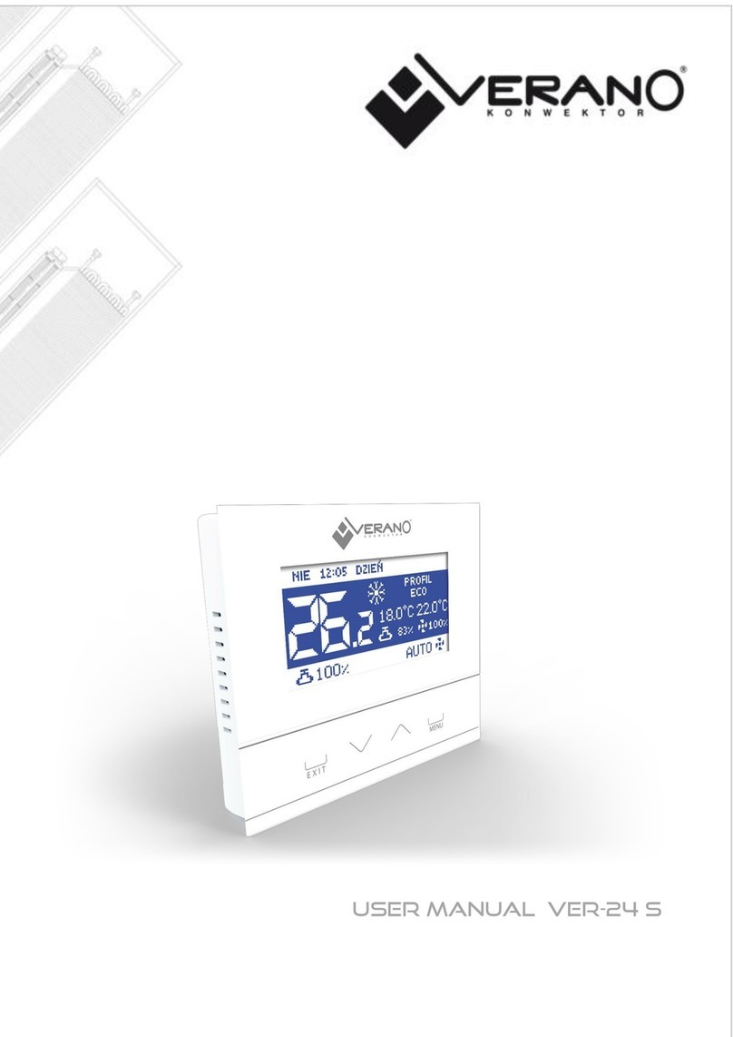
Verano VER-24 User manual

User’s manual VER-24

1

2
I. Safety ............................................................................................................................. 3
II. Device description.......................................................................................................... 4
III. Installing the controller................................................................................................... 4
IV. Operating the controller.................................................................................................. 7
IVa) Principle of operation..................................................................................................... 7
IVb) Description of main screen............................................................................................. 7
IVb) Controller operation modes ............................................................................................ 8
V. Controller functions – main menu options ............................................................................ 9
V.a) Selecting the profile..................................................................................................... 10
V.b) Temperatures settings ................................................................................................. 12
V.c) Time settings .............................................................................................................. 12
V.d) Schedule settings ........................................................................................................ 13
V.e) Screen settings ........................................................................................................... 13
V.f) Alarm clock settings ..................................................................................................... 13
V.g) Controller settings....................................................................................................... 14
V.h) Protections ................................................................................................................. 15
V.i) Language selection....................................................................................................... 15
V.j) Information about software ........................................................................................... 15
V.k) Stand-by mode ........................................................................................................... 16
V.1) Service settings .......................................................................................................... 16
VI. Controller functions – service menu options .................................................................... 16
VI.a) Temperature settings ................................................................................................. 17
VI.b) Selecting the system.................................................................................................. 17
VI.c) Selecting the mode .................................................................................................... 17
VI.d) Output configuration .................................................................................................. 18
VI.e) Fan advanced settings ................................................................................................ 19
VII. Alarms ...................................................................................................................... 20

3
I. Safety
Before using the device for the first time the user should read the following regulations carefully. Not
obeying the rules included in this manual may lead to personal injuries and device damage. The user's
manual should be stored in a safe place for further reference.
In order to avoid accidents and errors it should be ensured that every person using the device has
familiarized themselves with the principle of operation as well as security functions of the device. If the
device is to be sold or put in a different place, make sure that the user's manual is there with the device
so that any potential user has access to essential information about the device. The manufacturer does
not accept responsibility for any injuries or damage resulting from negligence; therefore, users are
obliged to take the necessary safety measures listed in this manual to protect their lives and property.
WARNING
The device should be installed by a qualified electrician.
The regulator should not be operated by children.
NOTE
Any other use than specified by the manufacturer is forbidden.
The technical condition of cables should be checked regularly. The user should also check if the
controller is properly mounted and clean it if dusty or dirty.

4
II. Device description
The application of the VER-24 regulator ensures convenient control over the Verano fan coil.
The VER-24 regulator has the following functions:
Controlling the room temperature
Smooth adjustment of the fan's revolutions
Smooth adjustment of the valve's opening degree
Controlling the valve ON/OFF
Daily schedule
Alarm clock
Parental lock
The controller's equipment:
a large, legible, color touch screen
a built-in room sensor
III. Installing the controller
The controller should be installed by a qualified person.
WARNING
Risk of fatal electric shock from touching live connections. Before working on the regulator, switch off
the power supply and prevent it from being switched on again.
The VER-24 regulator may be installed as a panel mountable on a wall.

5
First, the user should mount the rear installation cover to the wall where the room regulator will be
connected in the electrical junction box. Then, the user should connect the power supply cables.
The room regulator should be installed on catches
25

6
BLOCK CONNECTION SCHEME
CONNECTION SCHEME

7
IV. Operating the controller
IVa) Principle of operation
The VER-24 regulator controls the fan as well as the valves in order to maintain the set temperature in
the room. Depending on the selected mode, it increases the temperature in the room (heating mode)
or decreases it (cooling mode). The controller smoothly controls the fan's operation (depending on the
need, it gradually increases or decreases its revolutions) and the valve's operation (depending on the
need, it gradually increases or decreases the degree of its opening). Additionally, the controller may
adjust the operation of the second valve – opening or closing it, depending on the need.
IVb) Description of main screen
The controller is equipped with a large graphic display with a touch panel. The main screen displays
the current status of the controller's basic parameters.
Description of the main screen:
1. Information on the day of the week, hour and time of day
2. Icon for changing the operation mode:
- Heating –Sun icon
- Cooling –Snowflake icon
CAUTION
Function active when the option Manual heating /cooling is marked in the submenu
Mode selection in the service menu. When another mode is selected, the icon for
changing the operation mode is invisible and an icon informing on the enabled active
mode appears in the top right-hand corner.
3. Degree of valve opening with smooth adjustment.
4. Valid set temperature (depending on the selected profile and operation mode).
1
14
2
4
3
13
5
7
6
9
12
11
10
8

8
5. Information on the controller's active operation profile.
6. Entering the controller's main menu.
7. Fan revolution speed
8. Icons informing on the current fan speed:
- all three icons displayed – the fan operates with full speed
- two icons displayed – the fan operates with medium speed
- one icon displayed – the fan operates with minimum speed
- no icon – fan does not operate
9. Icon for changing the fan's operation mode. The fan may operate in the following modes:
- automatic – the fan's speed is adjusted by the controller's operation algorithm
- manual – three speeds
- disabled
CAUTION
Information on the current fan operation mode is saved in the controller's memory after
6 seconds from the last change of parameter.
10. Button used for increasing the set temperature –option active only in the profile Comfort. The
set temperature changed in this place is valid only until the user enters the controller's menu or
an automatic change of the operation profile (e.g. according to the schedule settings).
11. Strip for changing the set temperature settings –option active only in the profile Comfort. The
set temperature changed in this place is valid only until the user enters the controller's menu or
an automatic change of the operation profile (e.g. according to the schedule settings).
12. Button used for reducing the set temperature –option active only in the profile Comfort. The
set temperature changed in this place is valid only until the user enters the controller's menu or
an automatic change of the operation profile (e.g. according to the schedule settings).
13. Valve icon
- red –valve configured as heating,
- blue –valve configured as cooling
- crossed out valve icon –valve disabled
14. Current room temperature.
IVb) Controller operation modes
The controller may operate in two modes, regardless of the selected profile: heating or cooling. The
user selects the possibility to adjust particular modes in the submenu Service menu / Mode
selection. It is possible to adjust only one valid operation mode – marking the option Heating or
Cooling, or allow the manual switching of modes from the main screen position – marking the option
Manual heating / cooling
Operation mode Heating
After the user selects this mode, the controller activates the fan and opens the valves in order to
increase the temperature when it detects that the temperature in the room is lower than the set
temperature (setting in the submenu Temperature settings ). After the room temperature is
increased to the set value reduced by the value determined by the user (setting in the service menu in
the submenu Temperature settings ), the controller switches into gradual reduction of the fan's
revolutions and closing the valve.
After the set temperature is reached in the room, the fan is disabled and the valves are closed (the
fan's automatic mode is enabled).
Operation mode Cooling
After the user selects this mode, the controller activates the fan and opens the valves in order to reduce
the temperature when it detects that the temperature in the room is higher than the set temperature
(setting in the submenu Temperature settings ). After the temperature in the room is decreased to
the set value increased by the value determined by the user (setting in the service menu in the submenu
Temperature settings ), the controller switches into gradual reduction of the fan's revolutions and
closing the valve.
After the set temperature is reached in the room, the fan is disabled and the valves are closed (the
fan's automatic mode is enabled).

9
V. Controller functions – main menu options
During the regulator's normal operation the graphic display displays the main screen.. After the user
presses the menu button, it is possible to edit the controller's functions.
Due to the controller's complexity (great number of parameters to be edited), the menu was
divided into the main menu and the service menu – protected with a four-digit code. The main menu
contains the controller's basic operation parameters, e.g. mode selection, settings of set temperatures,
appearance of the main screen etc.
Main menu
Profile selection
ECO profile
Comfort profile
Profile protection
Profile schedule 1
Profile schedule 2
Profile schedule 3
Temperature settings
Comfort temperature
ECO min temperature
ECO max temperature
Protection min temperature
Protection max temperature
Time settings
Day from
Night from
Timer settings
Date settings
Schedule settings
Schedule 1
Schedule 2
Schedule 3
Screen settings
Screen brightness during the day
Screen brightness during the
night
Alarm clock settings
Disabled
Active on selected days
Active once
Waking hour
Waking day
Controller settings
Room temperature sensor
Fan revolution settings
Minimum revolutions
Medium revolutions
Maximum revolutions
Protections
Auto-lock enabled
Auto-lock disabled
Auto-lock PIN codeLanguage selection
Information about software
Stand-by mode
Service settings

10
V.a) Selecting the profile
The parameters in this submenu are used to select the
controller's operation profile.
Profiles available in the controller are used to maintain the
temperature in the room at the set level. The user may
select 3 various profiles (comfort, eco, protection) as well
as three different schedules (1, 2, 3).
COMFORT:
In this profile, the user adjusts one set temperature
(Tzad), Fig. 1, 2. If the temperature in the room decreases (heating mode ) or increases (cooling
mode ) by 0.1 °C, the controller will gradually begin to open the valve and will activate the fan. When
the temperature in the room is still decreasing (heating mode ) or increasing ( cooling mode ), the
controller will gradually open the valve. The valve will be completely open below the temperature Tzad
– delta (or above Tzad + delta). Fig. 2 presents the fan's operation.
Figure No 2 Chart of fan operation in the profile Comfort
Figure 1 Chart of valve operation in the profile Comfort

11
ECO, PROTECTION:
The profile PROTECTION operates similarly to the ECO profile. The only difference are the default values
of set temperatures settings:
Minimum temperature PROTECTION < minimum temperature ECO
Maximum temperature PROTECTION > Maximum temperature ECO
The profile PROTECTION is used to maintain optimum values in the room protecting the system against
freezing or overheating.
In this profile, the user adjusts two temperatures (Tzad_min, Tzad_max), Fig. 3.4. If the temperature
in the room decreases (heating mode ) below the temperature Tzad_min by 0.1 °C, the controller will
update the valve's and the fan's settings (according to the settings) in order to achieve the set
temperature in the room. If the temperature increases (cooling mode ), the adjustment takes place
similarly to the previous case.
Figure No 3 Chart of valve operation in the profile ECO, PROTECTION
Figure No 4 Chart of fan operation in the profile ECO, PROTECTION

12
•Profile schedule 1, 2, 3
Enabling one of the three schedules will cause the controller to operate according to the previously
defined program – the parameter Schedule settings
The schedules allows the user to adjust the requested profile (comfort, eco, protection) in a given hour
of the day (Menu / Schedule settings ).
V.b) Temperature settings
The parameters in this submenu allow the user to adjust
the set temperatures for the controller's particular profiles
(see the previous chapter). The user may change the
following temperatures:
•Comfort temperature - changing (editing) the
room's set temperature in the profile Comfort.
•ECO min temperature - changing (editing) the
room's minimum set temperature in the profile ECO.
•ECO max temperature - changing (editing) the
room's maximum set temperature in the profile ECO.
•Protection min temperature - changing (editing)
the room's minimum set temperature in the profile
PROTECTION.
•Protection max temperature - changing (editing)
the room's maximum set temperature in the profile
PROTECTION.
V.c) Time settings
After the user presses the Time icon in the main menu, a
screen allowing the user to change the timer settings, the
current date as well as to determine the time frames for
day and night appears.
•Day from / Night from
This option allows the user to change the hours in which
the controller switches to the night mode (Night from) as
well as will return to the day mode (Day from).
•Timer settings
This function allows the user to change the currently
displayed time.
•Date settings
This function allows the user to change the currently
displayed date.

13
V.d) Schedule settings
The parameters in this submenu are used for
programming particular schedules.
After the user selects the schedule the settings of which
the user wishes to edit, the display will show the following
settings screen. Using the icons or the user changes
the time interval (settings with accuracy to one hour). The
icons and allow the user to change the profile
assigned to a given hour. If the user wishes to copy a
setting to neighboring hours, the user should just press
the icon and then the icon or .
V.e) Screen settings
•Screen brightness during the day / screen
brightness during the night
After the user presses the icon, the user may adjust the
percentage value of screen brightness during the day and
during the night.
V.f) Alarm clock settings
In this function, the user adjusts the alarm clock. It is
possible for the alarm clock to be activated only on
selected days of the week (active on selected days) or to
be activated once.

14
- The user adjusts the waking hour with the use of the
"up" and "down" arrows.
- When the alarm clock is to be active only on selected
days of the week, the user should mark the days on which
the alarm clock is to be activated.
Controller screen view when the alarm clock is activated.
V.g) Controller settings
•Room temperature sensor
In this submenu, the user may calibrate the room
temperature sensor.
The calibration is performed during the installation or
after a longer period of using the regulator if the room
temperature measured by the internal sensor differs from
the actual temperature. Adjustment range: -10 to + 10ºC
with accuracy to 0.1⁰C.

15
•Fan revolution settings
This function allows the user to adjust the value of the
fan's revolutions in the manual operation mode (see
chapter Description of main screen) for particular speeds.
V.h) Protections
After the user presses the icon Protections in the main
menu, a panel used for changing the parental lock
settings appears. After the autolock is activated (the user
marks the option Auto-lock enabled) changes of the
controller's settings will be protected with a four-digit PIN
code - after the screensaver is activated after a period of
inactivity, it is not possible to browse the menu options
without entering the code.
In order to adjust the PIN code necessary to operate the
regulator (when the lock is active), the user should press
the icon Auto-lock PIN code.
CAUTION
The factory set PIN code is "0000".
V.i) Language selection
After the user presses the icon Language selection in the
main menu, a panel used for changing the language
appears.
V.j) Information about software
After the user presses this icon, the display will show the manufacturer's logo along with the software
version.

16
V.k) Stand-by mode
This function is used to activate the stand-by mode – the controller proceeds to the stand-by mode. It
will not control the operation of the fans or valves. This is an energy-saving mode. The controller
proceeds into its regular operation mode after the user touches the main panel.
V.1) Service settings
The service settings are used to adjust the advanced parameters of the controller's operation and should
be operated by qualified persons. The detailed description of these parameters may be found in the
next chapter. Access to parameters in the service menu is protected with a four-digit code.
VI. Controller functions – service menu options
The service menu should be operated by appropriately
qualified persons and is used primarily for settings of the
controller's additional functions such as set temperature of
deltas, output configuration etc.
Service menu
Temperature settings
Comfort delta temperature
ECO delta minimum temperature
ECO delta max temperature
Protection delta minimum
temperature
Protection delta max temperature
Selecting the system 2 pipes
Mode selection
Heating
Cooling
Manual heating / cooling
Output configuration
Output Q1
Output 1
Fan advanced settings
Heating activation temperature
Heating adjustment range
Cooling activation temperature
Cooling adjustment range
Minimum revolutions
Maximum revolutions

17
VI.a) Temperature settings
The parameters in this submenu are used to adjust the
deltas temperature values for particular operation
profiles. The delta value determines the moment in which
the controller switches into smooth control over the valve
and the fan – this is described in detail in the chapter
Profile selection.
The delta parameters may be adjusted for each set
temperature:
•Comfort delta temperature - applies to the
profile Comfort.
•ECO delta minimum temperature - applies to the profile ECO, the minimum set
temperature
•ECO delta max temperature - applies to the profile ECO, the maximum set temperature
•PROTECTION delta minimum temperature - applies to the profile PROTECTION, the
minimum set temperature
•PROTECTION delta max temperature - applies to the profile PROTECTION, the maximum
set temperature
VI.b) Selecting the system
This option is used to select the type of system for which
the controller is intended.
VI.c) Selecting the mode
The parameters in this submenu are used to determine the
controller's valid operation mode:
•Heating - no possibility to switch to Cooling mode from the level of the main screen. The user
marks this option if the system is planned for heating.
•Cooling - no possibility to switch to Heating mode from the level of the main screen. The user
marks this option if the system is planned for cooling.
If the user selects the Heating or Cooling function, the icon
for changing the operation mode disappears from the
controller's main screen. An icon signaling which mode is
valid is displayed in the right-hand top corner instead, this
may be seen on screenshot below – the valid mode in this
case is Cooling.

18
•Manual heating / cooling - the user may change the operation mode from the level of the
main screen – by pressing the icon for changing the operation mode
VI.d) Output configuration
The parameters in this submenu are used to configure the
operation of outputs:
•Output Q1
These settings apply to the operation of the valve
controlled with the use of the output ON/OFF.
The user determines the valve's role in the submenu
Type of output:
- Heating – after the user marks this option, the valve
controlled from the output ON/OFF will operate in the
heating mode.
- Cooling – after the user marks this option, the valve
controlled from the output ON/OFF will operate in the
cooling mode
- Disabled – after the user marks this option, the valve's
operation will be disabled.
Additionally, the user may change the settings of the following parameters:
- Heating hysteresis - This option is used to adjust the heating hysteresis used in the heating mode.
This is the difference between the set temperature and the temperature of return to operation
for example: when the set temperature has the value of 20°C and the hysteresis is 2°C. After
the set temperature is reached, namely 20°C, the valve is closed. The valve will open again after
the temperature decreases to 18°C.
- Cooling hysteresis - This option is used to adjust the cooling hysteresis used in the cooling mode.
This is the difference between the set temperature and the temperature of return to operation.
for example: when the set temperature has the value of 22°C and the hysteresis is 2°C. After
the set temperature is reached, namely 22°C, the valve is closed. The valve will open again after
the temperature increases to 24°C
•Output 1
These settings apply to the operation of the valve controlled with the signal 0-10V:
- Heating – after the user marks this option, the valve controlled with the signal 0-10V will operate
in the heating mode.
- Cooling – after the user marks this option, the valve controlled with the signal 0-10V will operate in
the cooling mode
- Disabled – after the user marks this option, the valve's operation will be disabled.

19
VI.e) Fan advanced settings
The parameters in this submenu are used to adjust the
fan's operation.
•Heating activation temperature
This parameter determines the shift downwards in the
scope of the fan's adjustment as compared to set
temperature in the heating mode.
•Heating adjustment range
The parameter determines the width of the range of
temperatures in which the controller is to smoothly
change the fan's revolutions in the heating mode.
Example:
The scheme below presents the operation of the valve and the fan with the following settings:
Set temperature: 20⁰C
Comfort delta temperature: 1⁰C
Heating activation temperature: 0.5⁰C
Heating adjustment range: 2⁰C
With the settings above, the valve will be open until the temperature 19⁰C is reached in the room (Tzad
– delta comfort). After this value is reached, the valve will gradually begin to close. When the set
temperature is reached in the room, the valve will close completely.
The fan will operate with full speed until the temperature 17.5⁰C in the room is reached (Tzad – Heating
activation temperature – Heating adjustment range) – after this value is reached, the fan will gradually
begin to reduce the revolutions until it is completely disabled when the temperature 19.5⁰C is reached
Other manuals for VER-24
1
Table of contents
Other Verano Thermostat manuals
Popular Thermostat manuals by other brands

ensto
ensto ECO500 Installation and operating instructions

ICM Controls
ICM Controls SC710LV Installation, operation & application guide

Viconics
Viconics PIR Ready7 VT76x7 Series Integration manual

Orbis
Orbis CHRONOS user manual

TOTALINE
TOTALINE CPE230RF owner's manual

Carrier
Carrier 53DFST2-NP installation instructions

HeatMat
HeatMat Programmable Thermostat user manual

EQ3
EQ3 L operating manual

Secure
Secure SCS317 User instructions

White Rodgers
White Rodgers 1F83-0471 Installation and operating instructions

Pego
Pego Expert nano 200NANO4CK1 Series Use and maintenance manual

Doepke
Doepke Dupline DRT 1 operating instructions