Heatit Z-PUSH BUTTON 2 User guide

IMPORTANT
PLEASE READ THIS BEFORE INSTALLATION
SAFETY & WARNINGS
• This device contains a button lithium battery that shall be
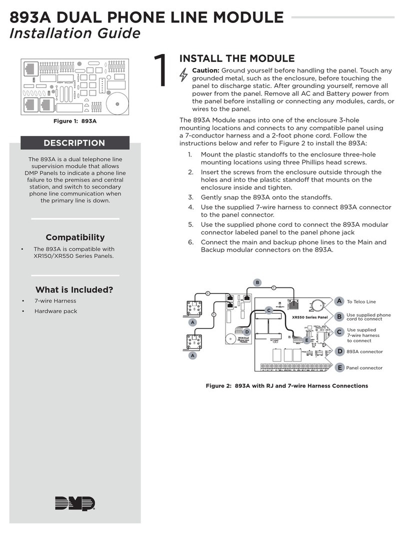
stored and disposed properly.
• DO NOT expose the device to moisture.
QUICK START
• Step 1: Turn on your remote control.
• Step 2: Activate inclusion mode on your Z-Wave controller.
• Step 3: Activate inclusion mode of your remote control by
pressing and holding down both Iand Obuttons together
over 3 seconds.
PRODUCT DESCRIPTION
The remote control is a Z-Wave device that can both control
other Z-Wave devices and activate scenes in Gateways.
Although it is controlling other devices, the device cannot act
as Z-Wave network controller (primary or secondary) and will
always need a Z-Wave network controller to be added into a
Z-Wave network.
The remote control has following functions:
1. Control of groups of other Z-Wave devices using ON, OFF and
Dim commands.
2. Activation of scenes in Gateway mode.
The encryption modes that the remote control supports are S0,
S2 Authenticated and S2 Unauthenticated. When the remote
control is being included into a Z-Wave network, you can use
your primary controller/gateway to enable one encryption
mode or disable encryption. (The primary controller/gateway
shall support encryption mode configuration).
INSTALLATION GUIDE
Please read carefully the enclosed user manual before
installation of remote control, in order to ensure an error-free
functioning.
The remote control unit supplied as complete set for flush
mounting in the standard circular European wall boxes with
60mm diameter.
ADDING TO A Z-WAVE NETWORK
Step 1. Make sure the remote control does not belong to
any Z-Wave network, short press any button, if LED indicator
does not turn on, the remote control does not belong to any
network, then continue step 2, if LED indicator turns on, it
means the remote control has already been added to a network,
please first set the remote control to removing mode (refer to
the part ”Remowing” of this manual), then continue to step 2.
Step 2. Set primary controller/gateway into adding mode
(Please refer to your primary controllers manual on how to turn
your controller into adding).
Step 3. Press and hold down both buttons Iand Oover 3
seconds, LED indicator turns on, the remote control will be
set to adding mode, and waiting to be added, after 10s LED
indicator blinks 6 times quickly to indicate successful adding.
HEATIT
Z-PUSH
BUTTON 2
Firmware 1.25
01.09.2018
Installers manual
Ver 2018-B
55.57 mm
71.20 mm
14,6m
55.57 mm
71.20 mm
m
Battery: CR 2450
Before the first use, please
remove the protective film
Back side
Press and hold down both keys together for 3s to be
added to or removed from Z-Wave network by Z-Wave
master (primary) controller.
Group 2:
Click to turn on,
Press and hold
down to increase
light intensity
Group 2:
Click to turn
off, Press and
hold down to
decrease light
intensity
Front side
The remote
control can be
fixed on the
wall with 3M
glue or screw.
55.57 mm
71.20 mm
14,6m
55.57 mm
71.20 mm
m

The remote control is a sleepy device, after adding it will
not enter into sleepy mode immediately, and will continue
activation status for 30s and wait data interaction from the
gateway, the LED indicator will stay solid on, please be patient
to wait LED indicator to turn off.
REMOVING FROM A Z-WAVE NETWORK
There are two removing methods:
Method 1: Removing from the primary controller/gateway as
follows:
1. Set the primary controller/gateway into removing mode
(Please refer to your primary controllers manual on how to set
your controller into removing).
2. Press and hold down both buttons Iand O over 3 seconds,
LED indicator turns on, the remote control will be set to
removing mode, and waiting to be removed, after 7s LED
indicator blinks 4 times quickly to indicate successful removing.
Method 2: Factory reset the remote control will force the
remote control to be removed from a network. (Please refer to
the part “Factory Reset”of this manual)
Note: Factory reset is not recommended for removing, please
use this procedure only if the primary controller/gateway is
missing or otherwise inoperable.
HOW TO CHECK WHETHER THE REMOTE CONTROL ALREADY
ADDED TO A NETWORK
Short press any button, if LED indicator does not turn on, the
remote control does not belong to any network, if LED indicator
turns on, it means the remote control has already been added
to a network.
If the remote control already belongs to a network, follow the
removing process before adding it in your network. Otherwise
adding of this device will fail.
FACTORY RESET
Press and hold down both I and O buttons together for over 10
seconds, LED indicator turns on and then blinks 4 times quickly
to indicate successful factory reset.
ASSOCIATION
Z-Wave devices control other Z-Wave devices. The relationship
betweenonedevicecontrollinganotherdeviceiscalledassociation.
In order to control a subordinate device, the controlling device
needs to maintain a list of devices that will receive controlling
commands. These lists are called ”Association Groups” and
they are always related to certain event is triggered (e.g. sensor
reports). In case the event happens all devices stored in the
respective association group will receive a common wireless
command.
ASSOCIATION GROUPS
Each group supports maximum 5 nodes for association, the
same device can be associated with multiple groups on
the remote control simultaneously, to ensure better control
experience, the remote control shall remove the associated
devices that are not under working status from association
groups in time.
ASSO-
CIATION
GROUPS
GROUP
NAME
MAX
NODES
DESCRIPTION
Group 1 Lifeline. 5 1. Send Command Class ”Device Reset
Locally Notification V1” to associated
devices of this group to report factory
reset information when factory reset the
remote control.
2. When remote control battery power
value changes, send Command Class
”Battery Report V1”to associated devices
of this group to report power value
information.
3. Short press/press and hold any but-
ton to send scene activation command
to the associated devices of this group
using Command Class“Central Scene
Notification V3”
Group 2 Launch 1 5 Short press I /O button of Group 2 to
send ON/OFF command to associated
devices of this group using Command
Class ”Basic Set V2”.
Press and hold down I / O button of
Group 2 to send light intensity increase/
decrease command to associated devices
of this group using Command Class
”Multilevel V4”.
SET AND UNSET ASSOCIATIONS
NOTE: ALL ASSOCIATION INFORMATION WILL BE CLEARED
AUTOMATICALLY ONCE THE REMOTE CONTROL IS EXCLUDED FROM
A NETWORK.
There are two methods to set associations:
1. Set association by operating primary controller/gateway to
send association command to the remote control:
When set association from primary controller/gateway, the
remote control shall be activated first, if it is not activated, you
should activate it manually.
The primary controller/gateway sends association command
to the remote control using“Command Class ASSOCIATION”or
“Command Class Multi Channel Association”
2. Set association by operating the remote control and devices
to be controlled:
To control a Z-Wave device from the remote control the node
ID of this device needs to be assigned to one of the two
association groups. This is a three-step process:
1. Press and hold down both buttons Iand O over 3 seconds,
LED indicator turns on.
2. Short press Ibutton of any group within 7s to associate the
device to this group, short press O button of any group within
7s to remove association of the device from this group.
3. Operate the device to be controlled to send Node
Information Frame (please refer to the device manual) within 10
seconds, or set the device to exclusion mode within 10 seconds,
since it will send Node Information Frame in exclusion mode,
LED indications are as follows:
- LED blinks twice to indicate that the remote control failed to
add the associated device (the association group has already

added maximum quantity associated devices that it supports ).
- LED blinks 5 times to indicate that the remote control added
the associated device successfully.
- LED blinks 8 times to indicate that the remote control removed
the associated device successfully.
TO REMOVE ALL ASSOCIATED DEVICES IN AN ASSOCIATION
GROUP ON THE REMOTE CONTROL DIRECTLY:
1. Press and hold down both buttons I and O over 3 seconds,
LED indicator turns on.
2. Click O button of any group on the remote control 5 times
continuously within 7 seconds to remove all associated devices
of this group, LED indicator blinks 8 times to indicate that the
associated devices are removed successfully.
- Short press or press and hold down any button to send scene
activation command to association Group 1 using Command
Class ”Central Scene Notification V3”.
- Short press I / Obutton, send ON/OFF command to all
associated devices of Association Group 2.
- Press and hold down I / Obutton, send light intensity
increase/decrease command to all associated devices of
Association Group 2.
How to communicate with the device
The remote control is under sleepy mode for most of the time to
save battery power. It can not receive wireless command under
sleepy mode. Before the gateway interacts data with the remote,
the remote control shall be activated manually first. Short press
any button to activate the remote control for 3s, and press and
hold down I and O buttons together over 1 second to activate
the remote control for 7s.
55.57 mm
71.20 mm
14,6m
55.57 mm
71.20 mm
m
Press and hold down both keys together for 3s to be
added to or removed from Z-Wave network by Z-Wave
master (primary) controller.
Group 2:
Click to turn on,
Press and hold
down to increase
light intensity
Group 2:
Click to turn
off, Press and
hold down to
decrease light
intensity
Front side
OPERATING THE DEVICE
Node Information Frame
The Node Information Frame is the business card of a Z-Wave device.
It contains information about the device type and the technical
capabilities.The add and remove procedure of the device is confirmed
by sending out a Node Information Frame. Besides this, it may be
necessary for certain network operations to send out a Node
Information Frame.
How to send out Node Information Frame:
Set the wall controller into adding/removing mode: Press and
hold down both I and O buttons over 3 seconds, LED indicator
turns on to indicate the wall controller has already sent out
Node Information Frame, the user can repeat the operation to
set the wall controller to quit“adding/removing mode”.

PRODUCT INFO Heatit Z-Push Button 2
• Battery operated wall switch with 2 push buttons
• Fits Gira System 55, Elko RS-16 and Schneider
Exxact frames
• Controls 1 group and up to 5 units
• Controls 4 scenarios via your gateway
• LED-diode
• Easy to install with screws and double-sided tape
• Supports encryption mode: S0, S2 Authenticated Class,
S2 Unauthenticated Class
TECHNICAL DATA
Protocol Z-Wave, 868,4 MHz
SDK 6.71.01
Chip Z-Wave 500 chip
Rated voltage 1 x CR 2450 battery
Push Button 2
Min/max installation temp.0 - 40°C
Relative humidity 8% - 80%
Nettwork range Up to 20 meters
(depending on surroundings)
IP Class IP 20
Size LxWxD 71,2 x 71,2 x 13,6mm
Explorer Frame Support Yes
Device Type Wall controller
Generic Device Class Switch Remote
Specific Device Class Switch Remote Multilevel
Routing No
Flirs No
Approvals CE
RoHS 2011/65/EU
COMMAND CLASSES
Supported Command Classes
• COMMAND_CLASS_ZWAVEPLUS_INFO_V2
• COMMAND_CLASS_ASSOCIATION_V2
• COMMAND_CLASS_MULTI_CHANNEL_ASSOCIATION_V3
• COMMAND_CLASS_CENTRAL_SCENE_V3
• COMMAND_CLASS_ASSOCIATION_GRP_INFO_V1
• COMMAND_CLASS_TRANSPORT_SERVICE_V2
• COMMAND_CLASS_VERSION_V2
• COMMAND_CLASS_MANUFACTURER_SPECIFIC_V2
• COMMAND_CLASS_DEVICE_RESET_LOCALLY_V1
• COMMAND_CLASS_POWERLEVEL_V1
• COMMAND_CLASS_BATTERY_V1
• COMMAND_CLASS_SECURITY_V1
• COMMAND_CLASS_SECURITY_2_V1
• COMMAND_CLASS_WAKE_UP_V2
• COMMAND_CLASS_SUPERVISION_V1
Controlled Command Classes
• COMMAND_CLASS_CENTRAL_SCENE_V3
• COMMAND_CLASS_BASIC_V2
• COMMAND_CLASS_SWITCH_MULTILEVEL_V4
• Multi Channel V3
• Security_V1
• Security_2_V1
Heatit Controls AB can
not be held liable for
typographical errors, other
errors or omittances in
our information.
Product specifications
may change without
further notice.
All electrical installations
must be carried out by a
licensed electrician.
The product must be installed
in accordance with national
building codes and our
installers manual.
Heatit Controls AB l Läkarvägen 4, 454 31 BRASTAD, SWEDEN
ART.NO. PRODUCT Z-WAVE
FREQUENCY
45 125 80 Heatit Z-Push Button 2
- battery operated wall switch
EU 868,4MHz

VIKTIG: LES INSTALLASJONSVEILEDNINGEN FØR
INSTALLASJONEN
SIKKERHET OG ADVARSLER
• Denne enheten inneholder et litiumbatteri som skal lagres
og kastes på forsvarlig vis.
• NB! Enheten må ikke installeres i våtrom eller på steder der
den kan utsettes for direkte fukt.
HURTIGGUIDE
Installasjon
• Trinn 1: Skru på veggbryteren.
• Trinn 2: Aktiver inkluderingsmodus på gatewayen.
• Trinn 3: Aktiver inkluderingsmodus på veggbryteren ved å
holde nede Iog Oknappene samtidig i 3 sekunder.
PRODUKTBESKRIVELSE
Heatit Z-Push Button 8 er en veggbryter som både kan
kontrollere Z-Wave-enheter gjennom assosiasjoner og aktivere
scener i gatewayen. Selv om bryteren kontrollerer enheter
gjennom assosiasjoner, kan ikke Heatit Z-Push Button 8
konfigureres uten en gateway.
Produktet kan brukes med to forskjellige konfigurasjons-
parametre:
1. Kontrollere grupper av Z-Wave enheter ved hjelp av ”PÅ”,
”AV”og dimme kommandoer.
2. Aktivering av scener fra gateway.
Krypteringsmoduser som støttes er S0, S2 Authenticated og
S2 Unauthenticated Class. Når veggbryteren skal inkluderes
i gatewayen kan du velge å inkludere veggbryteren i
sikkerhetsmodus. (Gateway må støtte krypteringsmodus for å
kunne bruke denne funksjonen).
INSTALLASJONSGUIDE
Les installasjonsveiledningen nøye før installasjon av
veggbryteren for å sikre feilfri funksjonalitet.
Veggbryteren leveres som et fullt sett for montering i
standardrammer i europeiske veggbokser med 55mm diameter,
f.eks. System 55, Elko RS16 og Schneider Exxact.
INKLUDERING (LEGGTIL I ET Z-WAVE-NETTVERK)
Trinn 1.
Hvis LED-indikatoren ikke lyser når du trykker på en knapp, kan du
gå videre til trinn 2.
Hvis LED-indikatoren lyser når du trykker på en knapp, må
enheten nullstilles etter å ha vært inkludert i et tidligere nettverk.
Se «Ekskludering» i installasjonsveiledningen. Fortsett deretter til
trinn 2.
Trinn 2. Sett gatewayen i inkluderingsmodus (Sjekk
brukerveiledningen på din gateway).
Trinn 3. Press og hold både Iog Oknappen i 3 sekunder.
LED-indikatoren vil skrus på, og veggbryteren vil bli satt i
inkluderingsmodus. Vent (ca. 10 sekunder) til den blir lagt til av
gatewayen. Vellykket inkludering vil bli indikert med 6 raske blink.
HEATIT
Z-PUSH
BUTTON 2
Firmware 1.25
01.09.2018
Installasjonsveiledning
Ver 2018-B
55.57 mm
71.20 mm
14,6m
55.57 mm
71.20 mm
m
Batteri: CR 2450
Fjern beskyttelsesfilmen før
første gangs bruk.
Bakside
Trykk og hold begge knappene i 3 sekunder
for å legge til/ erne fra gatewayen.
Gruppe 2:
Klikk for å skru på.
Trykk og hold for å
øke lysintensiteten.
Gruppe 2:
Klikk for å skru
av. Trykk og
hold for å senke
lysintensiteten.
Front
Den trådløse
bryteren kan
festes på
veggen med
dobbeltsidig
tape eller
skruer.
55.57 mm
71.20 mm
14,6m
55.57 mm
71.20 mm
m

Selv om veggbryteren er en batteridrevet enhet, vil den i 30
sekunder etter inkludering fullføre aktiveringsprosessen. Den vil
ikke kunne motta informasjon fra gatewayen. Mens den fullfører
aktiveringsprosessen vil LED-indikatoren lyse. Vær tålmodig og
vent til LED-indikatoren slutter å lyse.
EKSKLUDERING (FJERN ENHETEN FRA Z-WAVE-NETTVERKET)
Det er to typer ekskluderingsmetoder:
Metode 1: Ekskludering fra gateway.
1. Sett gatewayen i ekskluderingsmodus (se gatewayens
brukermanual).
2. Trykk og hold nede både I og O knappen i 3 sekunder.
LED-indikatoren vil skrus på, og veggbryteren vil bli satt i
ekskluderingsmodus. Vent til enheten ekskluderes. Etter ca.
7 sekunder vil LED-indikatoren blinke raskt 4 ganger i for å
indikere vellykket ekskludering.
Metode 2: Nullstill til fabrikkinnstillinger.
Dette vil tvinge veggbryteren til å bli ernet fra Z-Wave nett-
verket (se «Fabrikkinnstillingerl» i denne manualen).
NB! Nullstilling til fabrikkinnstillinger anbefales ikke som
fremgangsmåte for ekskludering. Denne metoden bør kun
brukes hvis gatewayen ikke er tilgjengelig.
SJEKK OM VEGGBRYTEREN ER INKLUDERT I ET Z-WAVE-
NETTVERK
Trykk på hvilken som helst knapp. Hvis LED-indikatoren ikke
lyser, er bryteren ikke inkludert i et nettverk. Hvis LED-indikator
skrus på, betyr det at veggbryteren er inkludert i et Z-Wave
nettverk.
Hvis veggbryteren allerede er inkludert i et Z-Wave nettverk må
den ekskluderes fra dette før den kan inkluderes i et nytt. Følg
instruksene for «Ekskludering».
FABRIKKINNSTILLINGER
For å sette enheten tilbake til fabrikkinnstillinger, trykk og hold
både Iog Oknappen samtidig. Etter ca. 10 sekunder vil LED-
indikatoren lyse, etterfulgt av 4 raske blink. Dette signaliserer
vellykket nullstilling.
ASSOSIASJONER
Heatit Z-Push Button2 kan kontrollere andre Z-Wave-enheter.
Forholdet mellom en kontrollerende enhet og enhetene som
kontrolleres av den kalles en assosiasjon.
For å kunne kontrollere en annen enhet, må veggbryteren
lagre en liste av enheter som mottar Controlling Commands.
Disse listene kalles assosiasjonsgrupper, og er alltid tilkoblet en
hendelse, enten manuell (for eksempel at brukeren trykker på en
knapp) eller automatisk (for eksempel ved et bestemt klokkeslett
eller en bestemt temperatur). Hvis hendelsen inntreffer, vil alle
enheter i den assosierte gruppen motta et felles trådløst signal.
ASSOSIASJONSGRUPPER
Hver gruppe støtter maksimum 5 noder for assosiasjon.
Den samme enheten kan være inkludert i mange grupper
samtidig. Enheter som ikke er konfigurert ernes automatisk fra
assosiasjonsgrupper.
LAGE OG FJERNE ASSOSIASJONER
NB! ALLE ASSOSIASJONER VIL BLI FJERNET NÅR ENHETEN FJERNES
FRA ZWAVENETTVERKET
Det er to måter å sette assosiasjoner på:
1. Lag assosiasjoner ved hjelp av gateway:
Når du skal lage assosiasjoner fra gatewayen, må veggbryteren
være lagt til i gatewayen. Hvis den ikke er inkludert i gatewayen
se «Inkludering» i denne installasjonsveiledningen.
Gatewayen sender assosiasjonskommandoer til veggbryteren
ved hjelp av «Command Class Association» eller «Command
Class Multi Channel Association».
2. Lag assosiasjoner ved hjelp av veggbryteren og enheter
som skal assosieres. For å kunne styre en Z-Wave-enhet fra
veggbryteren, må Node-ID fra denne enheten bli lagt til i en av
assosiasjonsgruppene.
Dette er en tre-stegs prosess:
1. Trykk og hold både Iog Oknappen i 3 sekunder. LED-
indikator vil lyse.
2. Trykk på Iknappen innen 7 sekunder for å assosiere enheten
i gruppen. Trykk på O knappen for å erne assosiasjonen fra
denne gruppen.
3. Send Node Information Frame fra enheten du vil legge til i
assosiasjonen. (Se enhetens installasjonsveiledning). Sett eventuelt
enheten i ekskluderings-/inkluderingsmodus innen 10 sekunder.
LED vil indikere på denne måten:
- LED blinker 2 ganger i en hurtig frekvens for å indikere at
assosiasjonen mislyktes (for eksempel fordi assosiasjonen
allerede har et maksimum med enheter inkludert).
- LED blinker 5 ganger for å indikere at veggbryteren la til
enheten i assosiasjonsgruppen.
- LED blinker 8 ganger for å indikere at veggbryteren ernet
enheten fra assosiasjonsgruppen.
ASSO-
CIATION
GROUPS
GROUP
NAME
MAX
NODES
DESCRIPTION
Group 1 Lifeline. 5 1. Send Command Class ”Device Reset
Locally Notification V1” to associated
devices of this group to report factory
reset information when factory reset the
remote control.
2. When remote control battery power
value changes, send Command Class
”Battery Report V1”to associated devices
of this group to report power value
information.
3. Short press/press and hold any but-
ton to send scene activation command
to the associated devices of this group
using Command Class“Central Scene
Notification V3”
Group 2 Launch 1 5 Short press I /O button of Group 2 to
send ON/OFF command to associated
devices of this group using Command
Class ”Basic Set V2”.
Press and hold down I / O button of
Group 2 to send light intensity increase/
decrease command to associated devices
of this group using Command Class
”Multilevel V4”.

FOR Å FJERNE ALLE ASSOSIERTE ENHETER I EN ASSOSIASJONS-
GRUPPE PÅ VEGGBRYTEREN DIREKTE:
1. Trykk og hold ned Iog Oknappen i 3 sekunder. LED-indikator
vil lyse.
2. Trykk O knappen 5 ganger innen 7 sekunder for å erne
alle assosierte enheter. LED-indikator vil blinke 8 ganger for å
indikere at enheter ble ernet.
HVORDAN BRUKE ENHETEN
- Kort trykk eller trykk og hold inne en knapp for å sende en
scene aktiveringskommando til Association Group 1 ved bruk av
Command Class ”Central Scene Notification V3”.
- Kort trykk på I/ O knappene, sender PÅ/AV signal til alle
enheter assosiert i Association Group 2.
- Trykk og hold I/ O knappene, sender signal for å øke/senke
lysintensiteten til alle enheter assosiert i Association Group 2.
Sleeping Unit
Veggbryteren er en Sleepy Unit og vil mesteparten av tiden
være i dvale. Den kan ikke motta trådløse signaler når den
er i dvale. Før gatewayen samhandler med veggbryteren, må
veggbryteren først bli aktivert. Kort trykk på en knapp for å
aktivere veggbryteren i 3 sekunder, deretter trykk og hold I
og Osammen over ett sekund for å aktivere veggbryteren i 7
sekunder.
Node Information Frame
Node Information Frame er visittkortet til en Z-Wave enhet. Den
inneholder informasjon om enheten som type og tekniske data.
Inkludering og ekskludering bekreftes ved at enheten sender ut
Node Information Frame. Utenom dette kan informasjonen også
trengs for andre spesiell oppgaver i Z-Wave nettverket.
How to send out Node Information Frame:
Hvordan sende ut Node Information Frame:
Sett veggbryteren i inkluderings-/ekskluderingsmodus:
Trykk og hold ned både Iog Oknappen i 3 sekunder. LED-
indikatoren vil skrus på for å indikere at veggbryteren har
sendt ut Node Information Frame. Brukeren kan gjenta denne
prosessen for å avbryte «Inkluderings-/ekskluderingsmodus».
55.57 mm
71.20 mm
14,6m
55.57 mm
71.20 mm
m
Trykk og hold begge knappene i 3 sekunder
for å legge til/ erne fra gatewayen.
Gruppe 2:
Klikk for å skru på.
Trykk og hold for å
øke lysintensiteten.
Gruppe 2:
Klikk for å skru
av. Trykk og
hold for å senke
lysintensiteten.
Front
PRODUKTINFO Heatit Z-Push Button 2
• Batteridrevet veggbryter
• Passer i Gira System 55, Elko RS-16 og Schneider Exxact
• Styrer 1 gruppe og inntil 5 enheter
• Styrer 4 scenarier via gateway
• LED-diode
• Enkel å installere med skruer eller dobbeltsidig tape
• Støtter krypteringsmodus S0, S2 Authenticated Class,
S2 Unauthenticated Class
TEKNISKE DATA
Protokoll Z-Wave, 868,4 MHz
SDK 6.71.01
Chip Z-Wave 500 chip
Spenning 1 x CR 2450 batteri
Trykknapp 2
Omgivelsestemperatur 0 - 40°C
Luftfuktighet 8% - 80%
Rekkevidde Inntil 20 meter,
(avhengig av bygningsmasse)
IP-klasse IP 20
Størrelse (LxBxH 71,2 x 71,2 x 13,6mm
Explorer Frame Support Ja
Device Type Wall controller
Generic Device Class Switch Remote
Specific Device Class Switch Remote Multilevel
Routing Nei
Flirs Nei
Sertifisering CE
RoHS 2011/65/EU
EL-NR. PRODUKT
45 125 80 Heatit Z-Push Button 2 - batteridrevet veggbryter

COMMAND CLASSES
Supported Command Classes
• COMMAND_CLASS_ZWAVEPLUS_INFO_V2
• COMMAND_CLASS_ASSOCIATION_V2
• COMMAND_CLASS_MULTI_CHANNEL_ASSOCIATION_V3
• COMMAND_CLASS_CENTRAL_SCENE_V3
• COMMAND_CLASS_ASSOCIATION_GRP_INFO_V1
• COMMAND_CLASS_TRANSPORT_SERVICE_V2
• COMMAND_CLASS_VERSION_V2
• COMMAND_CLASS_MANUFACTURER_SPECIFIC_V2
• COMMAND_CLASS_DEVICE_RESET_LOCALLY_V1
• COMMAND_CLASS_POWERLEVEL_V1
• COMMAND_CLASS_BATTERY_V1
• COMMAND_CLASS_SECURITY_V1
• COMMAND_CLASS_SECURITY_2_V1
• COMMAND_CLASS_WAKE_UP_V2
• COMMAND_CLASS_SUPERVISION_V1
•
Controlled Command Classes
• COMMAND_CLASS_CENTRAL_SCENE_V3
• COMMAND_CLASS_BASIC_V2
• COMMAND_CLASS_SWITCH_MULTILEVEL_V4
• Multi Channel V3
• Security_V1
• Security_2_V1
Heatit Controls AB tar
forbehold om typografiske feil,
andre feil eller mangler
i vår informasjon.
Produktspesifikasjoner
kan bli endret uten
ytterligere varsel.
Alle elektriske installasjoner
skal utføres av
autorisert installatør.
Produktet skal installeres
i henhold til gjeldende NEK 400
og installasjonsveiledning.
Heatit Controls AB l Läkarvägen 4, 454 31 BRASTAD, SWEDEN
Table of contents
Languages:
