HEATIZON SYSTEMS Gutter Melt SR User manual

www.heatizon.com
© 2017 Heatizon Systems
HEATIZON SYSTEMS
RADIANT HEATING AND SNOW MELTING SYSTEMS
GutterMelt® SR is a registered trademark of Heatizon Systems.
®
07-17

2

3
Table Of Contents:
Product Overview………………………………………………………………..…………………….………….4
Cable Specifications…………………………………………………………..……………….………………...5
Warnings and Reminders………………………………………………………………….…………………….6
GutterMelt®SR Cable Layout Design Guidelines …………………………………………………………..7
GutterMelt®Accessories………………………………………………………………………………………...9
GutterMelt®Activation ...……………………………………………………………………………………….11
Design and Installation………………………………………..……………………………….....……………13
Resistance Recording Page ..……………………………………………………….………………………..18
Warranty…………………………………………………………………..……………………………..………..19
Note: Before proceeding with the installation of GutterMelt SR Cable, be sure to read the entire manual.

4
Heatizon Systems GutterMelt®SR rain gutter, eaves trough, downspout, and eave
deicing systems provide heat to maintain water flow paths on eaves, and in gutters,
downspouts and drains. This heating cable is placed directly on top of the roofing
material and/or in the rain gutter, downspouts and drains of a building. Heatizon
Systems products can be activated by a large variety of activation alternatives ranging
from a simple switch to an automatic temperature moisture sensor.
ADVANTAGES
•Prevents costly damage to roofs, gutters and downspout drains by providing a path for water to exit
•May be applied anywhere snow or ice can accumulate
•May be used on all types of standard roof covering material
•May be installed in rain gutters and downspouts made of metal, plastic, etc
•Industry leading warranty - designed for reliability
•GutterMelt®SR is available in 5, 9, and 12 Watts/ft. Special orders deliver up to 24 Watts per foot at 32°F in iced water
•Field cut to length
• Many activation options including temperature/moisture sensors
• Finest quality SR cable available
FAST & EASY INSTALLATION
Heatizon Systems GutterMelt®SR system utilizes easy to install
SR cable to provide reliable freeze protection of roofs, gutters,
downspouts and roof drains. Simply run the cable in gutters
using foil tape with pressure sensitive adhesive to secure cable
placement, or Heatizon roof clips (Heatizon Part #HT386530 or
#HT386530R). Roof clips attach the cable to standard roof
covering material. The cable can also be inserted in downspouts
using downspout hangers or brackets (Heatizon Part #HT38411
or #HT386412) to support the heating cable. GutterMelt® SR
cable may be cut to length in the field making installation easy
and convenient.
VALUE
Winter has many freeze thaw cycles that can cause millions of dollars
of damage to roofs, gutters, downspouts, and drains every year. As
winter progresses buildings experience ice buildup which can lead to
roof damage, or damage caused by snow and ice falling from the roof.
These cycles can cause ice to accumulate and back up under
shingles, resulting in ice dams. In some cases, damage appears in the
form of soaked insulation, stained, cracked and damaged sheet rock,
damp, smelly, rotting wall cavities and stained, blistered and peeling
paint. Heatizon Systems has the products and expertise to effectively
solve potential winter issues and protect your investment by
managing ice dams, minimizing icicles, and keeping ice from
accumulating in gutters and downspouts.
What GutterMelt won’t do?
• Prevent snow movement on/off the roof
• Remove accumulated snow and ice from roofs, gutters and
downspouts
•
••
•Gutters •
••
•Downspouts •
••
•Roof Eaves
ENERGY EFFICIENT AND COST EFFECTIVE
GutterMelt®SR is 100% efficient and automatically adjusts its heat output and energy consumption as the temperature conditions
change. When precipitation is expected, simply energize the cable. The cable provides maximum melting power when snow or
ice is present, but will automatically regulate its output and save energy when the roof and gutters are clear of snow and ice.

5
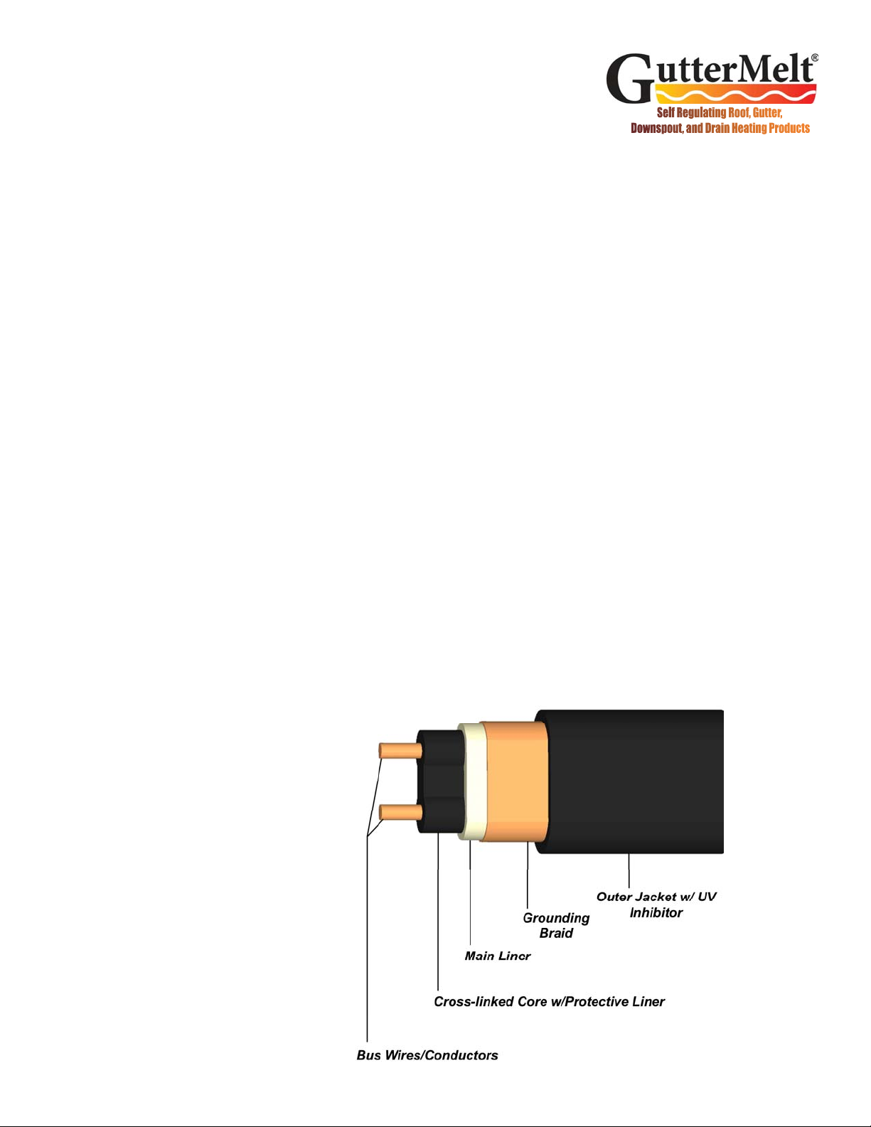
Self-Regulating Cable
Phase Conductor
Neutral Conductor
Ground Shield
120VAC, 277VAC
Connection
Phase Conductor
Phase Conductor
Ground Shield
208VAC, 240VAC
Connection
Electrical Connection Wiring
Note: GutterMelt®SR should be stored in a cool,
dry location.
Note: It is important that GutterMelt®SR be
installed only by qualified persons who are familiar
with the proper sizing, installation, construction and
operation of snow melting systems and the hazards
involved. GutterMelt®SR products are designed for
on roof, in rain gutter, and in downspout drain
applications.
Note: GutterMelt®SR must be installed in
accordance with the manufacturer’s installation
instructions, as well as with the National Electric
Code (NEC) and Canadian Electrical Code (CEC),
part 1, and local codes and regulations.
Note: Ground fault protection must be used when
installing all GutterMelt®SR products. Refer to the
NEC or CEC for specific requirements.
Note: Do not bend GutterMelt® SR Cable within
1.6” (40mm) of a termination or connection
between the GutterMelt®SR Heating Element and
the cold lead or power connection.
Required Tools:
2500VDC Megohmmeter
Digital Multimeter (DMM)
Screwdrivers
Wire Stripper
Crimping Tool
Utility Knife
Heatshrink Heating Device
GutterMelt® SR Cable Specifications
Watts per linear foot at
32°in iced water 5 9 12
Cable type Self Regulating (SR)
Copper bus wire 22 AWG Min
Maximum maintenance
temperature 185ºF (85ºC)
Maximum intermittent
exposure temperature
212ºF (100ºC)
T rating: T5
Voltage AC 120, 208, 240, 277
Maximum length Refer to product label
Approximate thickness/
width 0.25” x 0.50”
Bending radius 1”
Minimum spacing 2”
Standard spacing along
eave 18” to 24”
6
Warnings
•Failure to follow this Design and Installation Manual and/or
incorrect design, installation, handling or maintenance of
product may cause electrical shock, injury, damage or fire
•Disconnect all power to GutterMelt®SR and its activators prior
to handling, replacing or servicing
•Read this entire Design and Installation Manual prior to installing
GutterMelt®SR
•Do not twist, kink, or spiral GutterMelt®SR
•Always test GutterMelt®SR with a Megohmmeter Tester prior
to installing, once installation is complete, and prior to
energizing. All Megohmmeter tests must be performed at the
power termination of the GutterMelt®SR cable, between the
braided shield and the core wire(s)
•The minimum installation temperature is 40°F (5ºC)
•Use only copper wire from the distribution panel to the
GutterMelt®SR cable
•Do not allow the GutterMelt®SR Heating Element to touch or
cross other electrical conductors or gas lines
•GutterMelt®SR’s braid shield must be grounded to a suitable
earth ground
•Do not exceed the maximum circuit lengths listed in this Design
and Installation Manual
Always remember to test the insulation
resitance using a 2500 VDC Megohmmeter,
verify and record the actual results at specific
points throughout the installation process. A
resistance recording page is included in this
manual for this purpose. If the taken readings
are at anytime less than 20 megohms
replace or repair the damaged cable. Do not
energize the damaged GutterMelt®SR, and
call Heatizon Systems.
Roll the GutterMelt®SR spool to unreel the
heating element. Do not pull GutterMelt® SR
from the spool.
Verify that the supply voltage matches the
design voltage of the GutterMelt®SR product
you have purchased.
To avoid the hazard of electric shock,
disconnect all power prior to beginning
installation of GutterMelt®SR. Effectively
ground all installations prior to installing the
GutterMelt®SR Heating Element in
accordance with CSA Standard C22.1,
Section 10, and with the NEC.
Contact Heatizon Systems at 888-239-1232
with any additional questions you may have.
Reminders
Heatizon
GutterMelt®SR Cable
Available in 5W/ft, 9W/ft, & 12W/ft
7
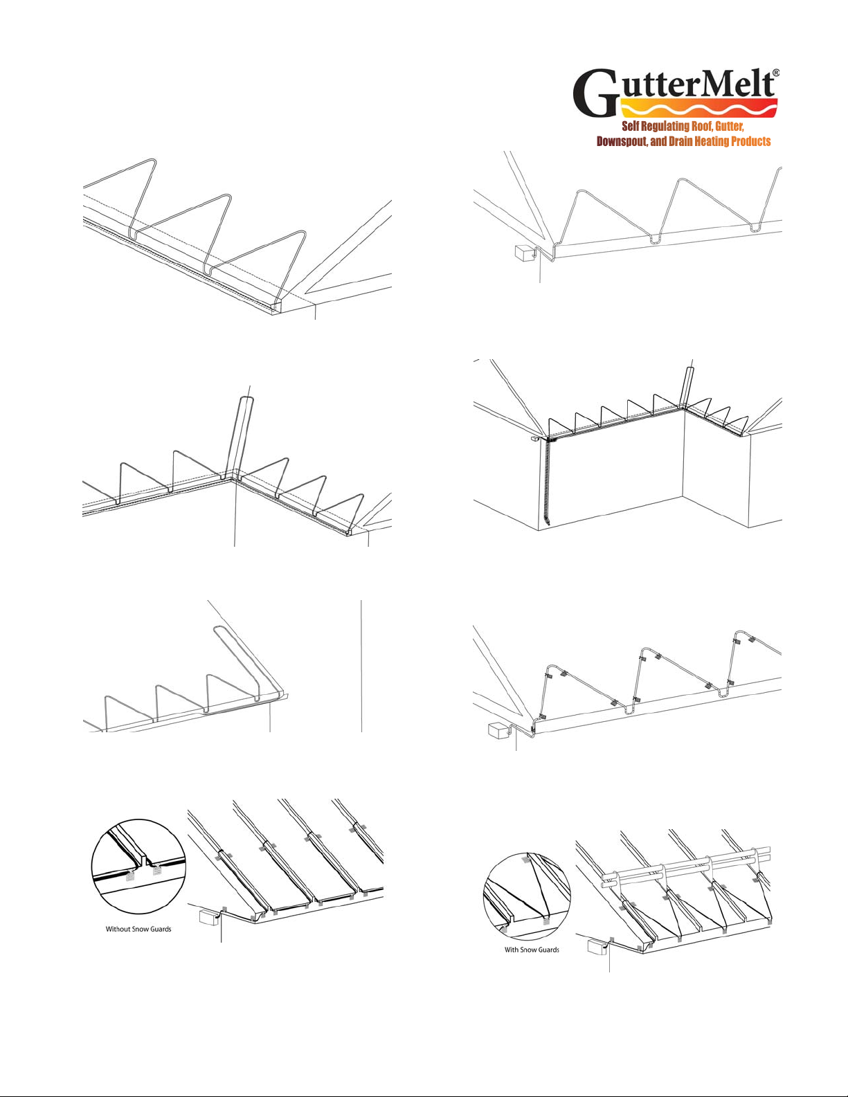
GutterMelt®SR Cable Layout Design Guidelines
Sloped Roof with Gutter. Run GutterMelt®up the roof until it extends
6” to 12” inside the exterior (cold) wall. Extend at least 2 to 3 inches into
the gutter with each loop.
Valleys. Extend GutterMelt®a minimum of two-thirds of the way up each
valley with a double run of GutterMelt®, as shown above.
Roof Intersection. Extend a loop of GutterMelt®a minimum of two-
thirds of the way up the slope, positioning the cable not more than 2 to 3
inches away from the adjacent wall.
Sloped Roof without Gutters. Heatizon recommends heated gutters
and downspouts to provide a continuous path for water. If a gutter is not
used, extend a drip loop of GutterMelt®cable past the shingle overhang
to allow water to drip free of the roof edge.
Roof Clips on a Sloped Roof with Asphalt Shingles. (Heatizon Part #
HT386530 or HT386530R)are attached with a screw or nail, GutterMelt®
cable is installed, then a water-sealing caulking is applied around the
clips, screws, and nails to prevent leaks.
Sloped Roof with Gutter and a Valley. Extend GutterMelt®a minimum
of two-thirds of the way up each valley. Extend the GutterMelt®into the
gutter. If there is no gutter, the GutterMelt®cable should extend past the
shingle overhang to allow water to drip free of the roof edge.
Standing Seam Roof without Gutters. Heatizon recommends heated
gutters and downspouts to provide a continuous path for water. The
cable is installed up and down each seam traveling to the next seam
along the roof face to protect it from sliding snow.
Standing Seam Roof without Gutters but with Snow Guards.
Heatizon recommends heated gutters and downspouts to provide a con-
tinuous path for water. If snow guards are used a zig zag pattern can be
used below the snow guards since the snow guards provide protection
for the cable. Install roof clips along the front face of the roof eave from
water to drain from the roof.
8
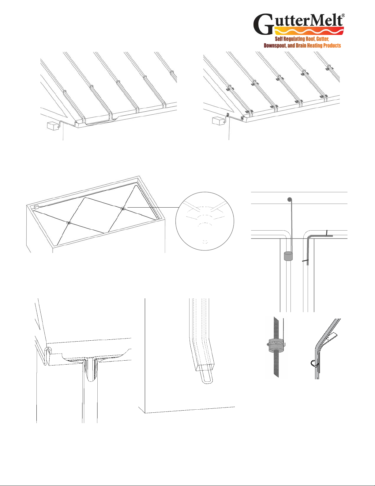
Roof Clips on Standing Seam Roof with Gutter. Roof Clips
are attached using Roof Clip Adhesive (Heatizon Part #
HT386530AD). Attach the clips to the roof and allow adhesive
to cure before threading cable through the clips.
Standing Seam Roof with Gutter. Run GutterMelt®up the
seam until it extends 6” to 12” inside of the exterior (cold) wall.
Extend at least 2 to 3 inches into the gutter with each loop.
Downspout Attachments and Sharp Edge
Protection. Use Downspout Hanger Kit
(Heatizon Part # HT386411) or Downspout
Hanger Bracket Kit (Heatizon Part #
HT386412) to attach GutterMelt®in down-
spout or drain to prevent damage to cable.
Downspouts. A continuous path for melt water can be maintained by running the Gut-
terMelt®inside the downspout to the bottom, and extend a small drip loop at the bottom
of the downspout. If the downspout drain extends below grade, GutterMelt®Cable
should extend into a heated area or below the frost line to effectively protect downspouts
and drains.
Downspout
Hanger Kit
Downspout Hanger
Bracket Kit
GutterMelt®SR Cable Layout Design Guidelines
Flat Roof. Position GutterMelt®heating cable around the perimeter of a flat roof. Run
GutterMelt®in valleys from the perimeter to the drain and extend the GutterMelt®
cable into drains and downspouts so that cable extends at least 12 inches into interior/
heated space.

9
GUTTERMELT® ACCESSORIES
Part Number Product Usage/Description
HT386530 Roof Clips,
Steel
•Use to attach GutterMelt® heating cable to roof surface
•Five (5) Double or ten (10) Single Clips per package
•Accommodate approximately 7 linear feet of GutterMelt®
cable
•Attached with a mechanical fastener or approved adhesive
sealant
HT386530R Roof Clips,
Aluminum
•Use to attach GutterMelt® heating cable to roof surface.
•HT386530R includes 10 clips—enough for approximately
7 eave feet of GutterMelt® cable
•Attached with a mechanical fastener or approved adhesive
sealant
HT386411
Downspout
Hanger Kit
•Use to suspend GutterMelt® heating cable in a gutter,
downspout or drain
•Attached with a mechanical fastener
•Includes three (3) downspout hanger assemblies
•Prevents heating cable from being damaged at gutter-to-
downspout and other transition points
HT386412
Downspout
Hanger Bracket
Kit
•Used to suspend GutterMelt® in downspout or drain
•GutterMelt® is secured to angled bracket; no fasteners
required
•Includes UV resistant plastic wire ties
•Includes two (2) downspout hanger bracket assemblies
•Prevents heating cable from being damaged at gutter-to-
downspout and other transition points
HT386521M End Seal Kit
•Use to terminate and seal the non-powered ends of
GutterMelt® heating cable
•Materials for three (3) end seals
•Provides water resistant seal
HT386505M Power
Connect Kit
• Use to terminate one powered end of GutterMelt® heating
cable into a junction box and to seal off one non-powered
end of cable
• Used for a hard-wired connection to supply power
• Includes materials for one (1) power connection assembly
• Includes one (1) end seal for non-powered cable end
HT386513 Splice Kit
• Connect two heating cables together
• Creates a water-resistant connection
• Spice Kit contains materials for two (2) splice connections
HT386513T Tee Kit
• Connect heating cables together to make a tee connection
• Creates a water-resistant connection
• Tee Kit contains materials for four (1) Tee connection
• Includes one (1) end seal for non-powered cable end
• Includes sealant and wire ties
10
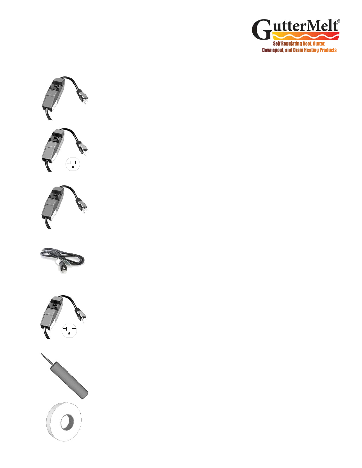
GUTTERMELT® ACCESSORIES
Part Number Product Usage Description
HT393473
10 Amp,
120VAC Plug in
Cord Set with
GFCI
•Used to terminate one GutterMelt® cable
•Includes one (1) connection assembly, one (1) end seal assembly,
and 1200 Watt three (3) foot cord
•Will work with up to 75 feet of 12W 120VAC, 100 feet of 9W
120VAC, or 190 feet 5W 120VAC GutterMelt® SR Cable
•Contains GFCI with 30mA test and reset
•Power “ON” indicator light
HT393473-120
20 Amp,
120VAC Plug in
Cord Set Kit
with GFCI
•Used to terminate one GutterMelt® cable
•Includes one (1) connection assembly, one (1) end seal assembly,
and 2400 Watt eight (8) foot cord
•Will work with up to 150 feet of 12W 120VAC, 200 feet of 9W
120VAC, or 300 feet 5W 120VAC GutterMelt® SR Cable
•Contains GFCI with 30mA test and reset
•Power “ON” indicator light
•Requires NEMA5 20 Amp Outlet Receptacle
HT393473-120-15
15 Amp,
120VAC Plug in
Cord Set Kit
with GFCI
•Used to terminate one GutterMelt® cable
•Includes one (1) connection assembly, one (1) end seal assembly,
and 2400 Watt eight (8) foot cord
•Will work with up to 115 feet of 12W 120VAC, 150 feet of 9W
120VAC, or 300 feet 5W 120VAC GutterMelt® SR Cable
•Contains GFCI with 30mA test and reset
•Power “ON” indicator light
•Requires NEMA5 20 Amp Outlet Receptacle
HT393473-PT
15 Amp,
120VAC Plug-
in Pig Tail Set
•Used to terminate one GutterMelt® cable
•Includes one (1) connection assembly, one (1) end seal assembly,
and eight (8) foot cord
•Will work with up to 115 feet of 12W 120VAC, 150 feet of 9W
120VAC, or 300 feet 5W 120VAC GutterMelt® SR Cable
•Standard Nema5 plug on one end, stripped wires on other end
HT393473-240
20 Amp,
240VAC Plug in
Cord Set with
GFCI
•Used to terminate one GutterMelt® cable
•Includes one (1) connection assembly, one (1) end seal assembly,
and 4800 Watt eight (8) foot cord
•Will work with up to 305 feet of 12W 240VAC, 390 feet of 9W
240VAC, or 660 feet of 5W 240VAC GutterMelt® SR Cable
•Contains GFCI with 30mA test and reset
•Power “ON” indicator light
•Requires NEMA6 20 Amp Outlet Receptacle
HT386530AD Roof Clip
Adhesive
•A 10.3 oz cartridge adhesive that is versatile, high strength, one
part, hard setting, pick proof, with superb tensile strength
•2000 psi tensile strength, tack free 18-24 hours, 50°F min install
•One cartridge covers about 30-40 roof clips
HT376548 Application
Tape •Used to secure GutterMelt® cable inside gutters or around pipes.
•Aluminum Application Tape, 150 ft. Roll

11
GUTTERMELT® ACTIVATION
Part Number Product Usage Description
M307
Plug In
Thermostatically
Controlled Device
Plugs into a 120VAC outlet and turns on
when temperature drops to 38ºF or less.
M325 Timer—12-hour
12 hour timer that can operate system from
0 to 12 hours. Features “hold” position; No
power required.
M326A
Temperature Moisture
Sensor - One 30A
Contact
Activates System when moisture is detected
and temperature is below set point. Leaves
system on for up to 6 hours. Requires 100-
277VAC, Switches up to one 30A Loads.
M326A-2Z
Temperature Moisture
Sensor - Two 30A
Contact
Activates System when moisture is detected
and temperature is below set point. Leaves
system on for up to 6 hours. Requires 100-
277VAC, Switches up to two 30A Loads.
M326ARS
Temperature Moisture
Sensor - with Gutter
Mounted Sensor - One
30A Contact
Activates System when moisture is detected
and temperature is below set point. Leaves
system on for up to 6 hours. Requires 100-
277VAC, Switches up to one 30A Loads.
M326CDP
Snow & Ice Sensor/
Controller Display Panel
option
Snow & Ice Sensor/Controller Display Panel
option for M326A Series Sensor line. Can
control, monitor and override the Ice and
Snow Sensor/Controller from remote
locations. Monitor the status, operating
mode and activation state of the sensor.
Requires no batteries or AC power - uses
power from the snow sensor. May be
installed as much as 800 feet away from the
snow sensor.
M336 Series Electronic Temperature
Controller
Electronic Temperature Controller with liquid
crystal display to produce constant readout.
Touch keypad to program wide set point
temperature range (-30°F to 220 °F) and
differential adjustment (1°F to 30°F).
Remote temperature sensing up to 400 feet.
Requires 120VAC or 240VAC to operate.
Also available with 2 Stage Temp Control.

12
GUTTERMELT® ACTIVATION
Part Number Product Usage Description
M330 Relay
Panel Series Heatizon Relay Panel
30A & 50A
Heatizon Relay Panel requires 120V, for
120/208/240/2 /480 VAC; Also accepts
activation devices that switch 12V DC.
Contains four relays, master rocker switch, and
four auto/manual area rocker switches. M330
switches up to four 30AMP loads. M330-50
switches up to four 50AMP loads. M330-G
Model includes GFEP.
M330G Relay
Panel Series Heatizon Relay Panel
30A & 40A with GFEP
Heatizon Relay Panel requires 120V, for
120/208/240/2 /480 VAC; Contains four
relays, master rocker switch, and four auto/
manual area rocker switches. M330-G
switches up to four 30AMP loads. M330G-40
switches up to four 40AMP FLA loads. Both
include GFEP.
M530 Series
Heatizon Contactor
Panel 50A with and
without GFEP
The M530 Contactor Panel Series can control
1-8 circuits at 208/240/480 VAC, or 1-16 circuits
at 120/277/600 VAC and is compatible with
many Heatizon activation devices. The M530
do not include GFEP.
M346 Heatizon Monitor
Station Selector Box
Allows up to 12 zones/panels to be activated
and monitored by one activation device.
Provides two different delay features. Powered
by 12VDC, provides 24VAC for activation
device as well as up to 12 circuits of monitoring.
M332 Gutter Controller
Gutter Controller allows Heatizon Systems Line
Voltage Cables to be turned on and off
whenever a Tuff Cable or ZMesh system is
turned on and off. Designed to fit over a
standard electrical outlet box. Switches
120/208/240/277 VAC.
M435
Roof, Gutter and Pipe
Moisture
Sensor, Outdoor
Temperature Sensor
and Controller.
Gutter/Roof Deicing with Moisture Sensor,
Outdoor Temperature Sensor and Controller.
Designed to lay in gutters or hang in
downspouts and pipes. The moisture sensor
detects moisture while the outdoor temperature
sensor monitors ambient temperature. Included
up to 2 zones and 3 output relays with 16A load
switch capability.
M515/M515G
Temp Control J-Box
120/277VA
Activates System when temperature is below
set point. 0°- 50°F : Temperature Selection
5°F Temperature Differential. Automatic
Activation for reliable system operation.
Switches 120/277 VAC 50/60hz. FLA 20A
@120VAC - FLA 16A @277VAC.
M516/M516G Temp Control J-Box
208/240VAC
Activates System when temperature is below
set point. 0°- 50°F : Temperature Selection
5°F Temperature Differential. Automatic
Activation for reliable system operation.
Switches 208/240 VAC. 30A @208VAC - 30A
@240VAC

13
Design and Installation
Typical Components of a GutterMelt®SR system include:
•GutterMelt SR heating cable
•Activation device, automatic or manual
•Power connect Kit(s) and End Seal Kit(s)
•Roof Attachment Clips with fasteners and/or adhesive
•Downspout Hanger Kits
•Relay Panel or Contactor Panel for larger projects
Necessary Information:
•Length of eaves, gutters, and downspout drains to be heat traced
•Distance from eave edge to inside the outside wall
•Voltage Available
•Type of Roof covering material
Draw a sketch of the area where GutterMelt®SR snow melt will be
installed. The sketch should show all measurements and dimensions
in order to determine the area to be snow melted. Determine the
location for the GutterMelt®SR temperature/moisture sensor or other
activation device.
Note: GutterMelt®SR is designed for snow melt applications
and to provide a path for water to exit the roof, gutter, and
downspout drain.
STEP 1 PLAN THE LAYOUT
Note: Make certain to plan for the movement of the water created
when GutterMelt®SR melts snow and/or ice from the roof, gutters
and/or downspouts to an acceptable refreeze location.
Annual Maintenance
Remove all debris from gutters and downspouts.
Verify the integrity of the GutterMelt®SR by conducting a visual inspection
and checking the insulation between the heating elements and the ground
shield with a Megohmmeter. Record the value if it exceeds 20 megohms
for GutterMelt®SR Cable. If damage to GutterMelt®SR Heating Cable is
discovered, and/or the Megohmmeter test yields a megohms reading less
than 20, then correctly repair or replace the GutterMelt® SR with new cable
prior to energizing.
Warning: Always disconnect power to GutterMelt® SR and its
activators prior to handling, replacing and/or servicing.
MEASURE AND
RECORD
RESISTANCE
14
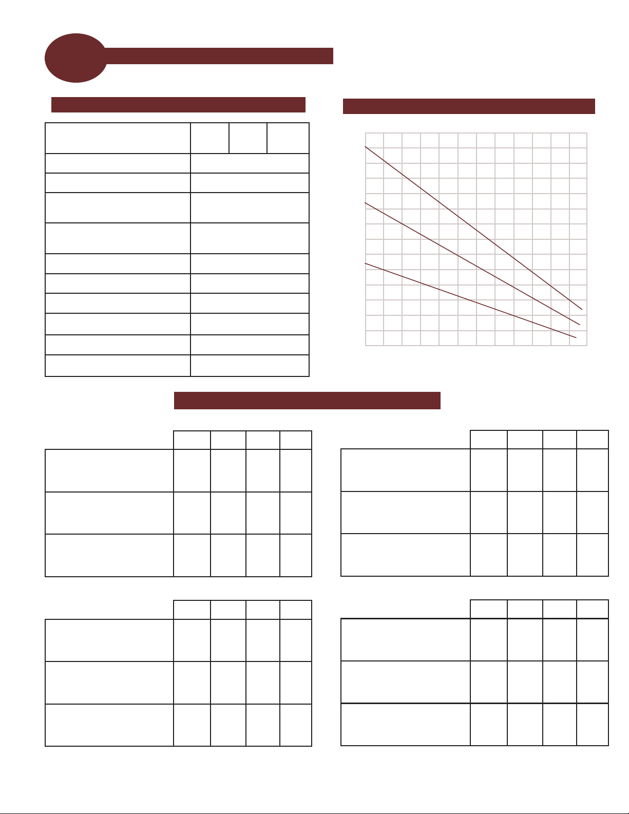
STEP 2 GUTTERMELT®SR SPECIFICATIONS
FIGURE 1
PERFORMANCE RATINGS POWER OUTPUT CURVE
BREAKER SIZING AND MAX CIRCUIT LENGTH
0 50 70 90 110 130 150
2
0
4
6
8
10
12
14
15A 20A 30A 40A
5GM1 If started at 40ºF
0ºF
-20ºF
300
200
180
—
270
230
—
330
330
—
—
—
9GM1 If started at 40ºF
0ºF
-20ºF
150
95
85
200
125
100
210
190
170
—
210
210
12GM1 If started at 40ºF
0ºF
-20ºF
115
70
60
150
95
85
180
145
120
—
180
165
120 Volt Breaker Sizing vs Max Circuit Length (ft)
15A 20A 30A 40A*
5GM2 If started at 40ºF
0ºF
-20ºF
660
410
360
—
560
480
—
660
660
—
—
—
9GM2 If started at 40ºF
0ºF
-20ºF
295
195
170
390
250
225
420
375
340
—
420
420
12GM2 If started at 40ºF
0ºF
-20ºF
230
150
130
305
200
175
360
300
260
—
360
360
240 Volt Breaker Sizing vs Max Circuit Length (ft)
Temperature, ºF
Power Output, Watts/Ft
5GM
9GM
12GM
15A 20A 30A 40A*
5GM1 If started at 40ºF
0ºF
-20ºF
505
475
420
—
650
560
—
765
765
—
—
—
9GM1 If started at 40ºF
0ºF
-20ºF
320
210
185
425
270
245
455
405
370
—
460
460
12GM1 If started at 40ºF
0ºF
-20ºF
240
155
135
315
210
180
375
310
270
—
375
375
208 Volt Breaker Sizing vs Max Circuit Length (ft)
15A 20A 30A 40A*
5GM2 If started at 40ºF
0ºF
-20ºF
570
355
310
—
485
415
—
570
570
—
—
—
9GM2 If started at 40ºF
0ºF
-20ºF
270
180
155
355
230
205
385
345
310
—
385
385
12GM2 If started at 40ºF
0ºF
-20ºF
220
140
125
290
190
165
340
285
245
—
340
340
277 Volt Breaker Sizing vs Max Circuit Length (ft)
* Appropriate sized butt splices may need to be sourced separately
Watts per linear foot at 32°in
iced water 5 9 12
Cable type Self Regulating (SR)
Copper bus wire 22 AWG Min
Maximum maintenance
temperature 185ºF (85ºC)
Maximum intermittent
exposure temperature
212ºF (100ºC)
T rating: T5
Voltage AC 120, 208, 240, 277
Maximum length Refer to product label
Approximate thickness/width 0.25” x 0.50”
Bending radius 1”
Minimum spacing 2”
Standard spacing along eave 18” to 24”

15
STEP 4 PREPARE AREA
Design and Installation
Ensure that the roofing material, gutters and/or downspout drains
have been properly installed, and that drainage has been satisfactorily
addressed.
Eliminate any nails, staples, or any other objects that may damage the
GutterMelt® SR Heating Element prior to installation.
Clean and dry the rain gutters so that the provided foil tape will adhere
to the bottom and hold the GutterMelt® SR cable in place.
Determine the location of the connection points between the power
supply and the GutterMelt®SR Cable.
Next, determine the location of the activation device.
Remember, an automated activator is the “eyes and ears” of the roof,
gutter, and downspout system. It is important that it be installed in a
location that will allow it to turn the roof deicing system “on” when it is
needed and “off” when it is not needed.
Manual activators require human action—as a result they should be
placed in a location that is convenient and easily accessible.
STEP 6 LOCATION SELECTION
STEP 3 CONTACT YOUR GUTTERMELT®SR SUPPLIER
Contact your GutterMelt® SR supplier for assistance in ordering the
material needed. When materials arrive, examine the GutterMelt®
SR roof deicing system design, and compare the list of materials
ordered to those received.
Remove the GutterMelt®SR Heating Element from the box. Using a
2500 Vdc Megohmmeter, check the insulation resistance of the
Heating Element to make certain it is greater than 20MΩ. Confirm the
Megohmmeter result by measuring the resistance with a Digital
Multimeter and record the value measured on Resistance Recording
Table at the back of this manual. Resistance measurement must be
taken several times during the installation process: Immediately upon
removal from the packaging and after installation of the heating
element. GutterMelt®SR should also be checked for electrical
continuity.
STEP 5 MEASURE & RECORD RESISTANCE
MEASURE AND
RECORD
RESISTANCE
16
Design and Installation
STEP 8 INSTALL GUTTERMELT® SR HEATING ELEMENT
Install the selected activator by carefully following the specific set of
instructions that were included in the packaging.
STEP 7 INSTALL THE ACTIVATOR
Warning: Do not allow the sensor conduit to cross the Gutter-
Melt®SR Heating Element. Do not allow any part of the activa-
tor to touch the GutterMelt® SR Heating Element.
Note: Always roll or uncoil the GutterMelt®SR to
unreel the heating element. Do not pull
GutterMelt®SR from the spool or coil. Never
energize GutterMelt®SR Heating Cable while it is
rolled or coiled on the spool.
Using the determined spacing of GutterMelt®SR Heating Element, and
the calculated length of GutterMelt®SR Heating Element, begin the
installation. Heatizon Systems recommends a maximum 2 foot
spacing along the eave edge for roof applications, and two runs of
GutterMelt® SR for gutter and downspout applications. Note that the
minimum distance between the GutterMelt®SR Heating Element runs
should not be less than 2 inches.
Install the GutterMelt®SR Heating Element so that the starting and
ending connection points and any activation sensor are in their desired
locations. Make certain that the power end of GutterMelt®SR Cable
returns back to the GutterMelt®SR Termination Box, Junction Box, or
Heatizon Relay Panel.
Begin laying the GutterMelt®SR Heating Element in and across the
area to be melted in evenly spaced runs.
Use Roof Clips purchased from your Heatizon Systems Distributor to
attach GutterMelt®SR to the roof covering material.
Use Foil Tape purchased from your Heatizon Systems Distributor to
attached GutterMelt® SR to the rain gutter.
Use Downspout Hangers purchased from your Heatizon Systems
Distributor to install GutterMelt® SR into the downspouts or drains.
Warning: Do not damage or subject the
GutterMelt®SR Heating Element to mechanical
or shear stress. Never cut or damage the
insulator on GutterMelt®SR Heating Element.
Do not allow GutterMelt® SR to cross or touch
gas lines or other electrical conductors.
Note: Visually check GutterMelt® SR Heating
Cable for breaks, cuts, nicks, etc. If damage has
been done to GutterMelt®SR Heating Cable or
any of its components, please file a claim with the
delivery service and call Heatizon Systems, 888-
239-1232.
MEASURE AND
RECORD
RESISTANCE
STEP 9 INSTALL GUTTERMELT® END KIT, POWER CONNECTION KITS
Commonly used connection kits and accessories are listed in this manual. See
www.heatizon.com for additional information.
After Installing GutterMelt®SR Heating Element take resistance
measurements. Using a 2500 Vdc Megohmmeter, check the insulation
resistance of the Heating Element to make certain it is greater than
20MΩ. Confirm the Megohmmeter result by measuring the resistance
with a Digital Multimeter and record the value measured on Resistance
Recording Table at the back of this manual. Resistance measurement
must be taken several times during the installation process:
Immediately upon removal from the packaging, after installation of the
heating element. GutterMelt®SR should also be checked for electrical
continuity.

17
Design and Installation
STEP 13 COMPLETE WARRANTY CERTIFICATE
Mail in the warranty certificate immediately after installing the GutterMelt® SR
system. Failure to complete the warranty card could void the manufacturer’s
warranty. The warranty is subject to the guarantee conditions listed on the
warranty certificate, and upon documentation that the required resistance
readings were completed. You may wish to keep a copy of the warranty card
for your reference.
STEP 10 CONNECT POWER SUPPLY & ACTIVATION
The connection of an acceptable ground fault protection device power supply and the activation device must be
done in accordance with the National Electrical Code (NEC) and the Canadian Electrical Code (CEC).
The braided shield from GutterMelt® SR Cable must be wired to Ground for all primary power installations.
Caution: Never energize GutterMelt®SR until:
1. The GutterMelt®SR Cable has been verified to be free of damage.
2. All splices and all power kit and end kit connections have been inspected.
3. A Megohmmeter Test has been used to verify a minimum of 20 MegOhms between the
heating element and the braided shield.
STEP 12 COMPLETE AND ATTACH LABELS
STEP 11 TROUBLESHOOTING
Problem: GutterMelt®SR Cable fails the Megohmmeter Test
Potential Causes:
• Check field installed power/end terminations and connection splices; correct as necessary
• Inspect the GutterMelt®SR Cable for damage to the insulator, exposed braided shield, and/or contact between
the braided shield and the core wire(s). Replace entire length of damaged GutterMelt®SR Cable
Call Heatizon Systems technical support @ 801-293-1232 if additional assistance is required.
Note: In the event the power/end termination or splices are not the cause of the failed Megohmmeter
Test and the GutterMelt®SR Cable has not been damaged in any way, remove and replace the
entire length of GutterMelt® SR. For Warranty claims, please return the entire length of GutterMelt®
SR to Heatizon Systems, with the end termination and power termination connections intact, for
evaluation prior to replacement.
Place the included labels in the following locations:
• Electrical Panel Label — Inside door at electrical service panel. This
label matches the information printed on the GutterMelt® SR Cable
• Stop Sign Warning Label — on or near the area to be heated by
GutterMelt®SR Cable

18
Resistance Recording Page
Use a Digital Multi Meter to measure continuity through the GutterMelt®SR Heating Element, and no
continuity between the heating element and the braided ground shield. GutterMelt®SR Cable should be
tested using a megohmmeter set at 2500 VDC at least twice. The measured value should not be less
than 20 Megohms. Record all test results below.
Prior to Installation (When
removed from Package)
After Installation of
GutteMelt® SR Heating
Element
MΩ@ 2500VDC
MΩ@2500VDC
Date Time
Date Time
Customer Warranty Information
MEASURE AND
RECORD
RESISTANCE
Name
Address
City State
Phone Email
Zip
Purchased Product Details
Watts Volts Ω
Watts &
Volts Ohms
Sq. Ft.
Model Size
Serial Number
(if applicable)
Manufacture
Date
19
Heatizon Systems warrants GutterMelt® SR Heating Element to be free from defects in material and workmanship for a period of ten (10) years and
Activation Device(s) for a period of one (1) year. Such warranty periods shall commence on the date of shipment by Heatizon Systems. If any parts are
found to be defective in manufacture during such time period, Heatizon Systems will, at its sole option, replace or repair defective parts.
This Limited Warranty applies only if articles sold hereunder (a) are selected, designed, and installed according to instruction and operation manuals
furnished by Heatizon Systems and installed in a “workmanlike manner” according to the building association standards adopted by Heatizon Systems,
(b) remain in their originally installed location, (c) are connected to proper power supplies, (d) are not misused or abused, (e) show no evidence of tam-
pering, mishandling, neglect, damage (accidental or otherwise), modifications or repair without the approval of Heatizon Systems, or damage done to
the product by anyone other than Heatizon Systems, and (f) are installed in accordance with applicable code requirements. Any warranty claims must
be made in writing, no later than one (1) month following expiration of the warranty period, and must be accompanied by the warranted part or compo-
nent. Any claim not made in such manner shall not be honored by Heatizon Systems.
This Limited Warranty does not cover:
1. The workmanship of any installer of Heatizon Systems radiant panel heating products.
2, Any Heatizon Systems radiant heating products that have a failure or malfunction resulting from improper or negligent operation, installation, acci-
dent, abuse, misuse, unauthorized alteration or improper repair or maintenance.
3. Any Heatizon Systems radiant heating products that have had components not purchased from Heatizon Systems integrated into or connected to
them.
4. Any labor costs for removal of alleged defective part(s) and/or reinstallation of replacement part(s), transportation to and from Heatizon Systems (if
necessary) and any other material necessary to perform the exchange or repair.
5. Any Heatizon Systems heating products that have not been properly registered by completion and return of the Warranty Registration Card attached
hereto within ninety (90) days of the date of sale..
DISCLAIMER OF WARRANTIES:
This warranty described above is in lieu of all other warranties, express or implied, including but not limited to any implied warranties of
fitness for a particular purpose and merchantability. Heatizon Systems expressly disclaims and excludes any liability for losses, expenses, inconven-
iences, consequential, incidental, indirect, or punitive damages for breach of any express or implied warranty. By installing and/or purchasing Heatizon
Systems products, you accept the terms of this limited warranty.
Some states do not allow the exclusion or limitation of incidental or consequential damages, or limitations on how long an implied warranty
lasts, so the above limitations and exclusions may not apply to you. This Limited Warranty gives you specific legal rights, and you may also have other
rights which may vary from state to state.
Heatizon Systems GutterMelt® SR Warranty
Mail: Heatizon Systems
4137 South 500 West
Murray, UT 84123
USA
Phone: (801) 293-1232
Toll Free: (888) 239-1232
Fax: (801) 293-3077
Email: [email protected]
Website: www.heatizon.com
How to make a Warranty Claim
1. Gather the following information:
•Date of purchase
•Who product was purchased from
•Date of installation, if installed
•Names and phone numbers of electrician/installer
•Completed resistance recording page from installation
•Serial number (if applicable) from product label
2. Contact Heatizon Systems for a Return Materials Authorization number, and information on the next
required steps to complete your warranty claim.

20
Mail: Heatizon Systems
4137 South 500 West
Murray, UT 84123
USA
Phone: (801) 293-1232
Toll Free: (888) 239-1232
Fax: (801) 293-3077
Email: [email protected]
Website: www.heatizon.com
Table of contents
Other HEATIZON SYSTEMS Heating System manuals

Popular Heating System manuals by other brands


International Thermal Research
International Thermal Research Oasis operating manual

CALEFFI
CALEFFI SATK50 Series quick start guide

Warmup
Warmup WHP1 installation manual

Mikrofill
Mikrofill Maxi Single Technical documentation

EngA
EngA ENGINEERED AIR HE Series Installation, operation and maintenance manual

HeatMat
HeatMat Mirror Demister installation instructions

Vectaire
Vectaire EVO220DC Installation, operating and maintenance instructions

BriskHeat
BriskHeat SLCBLSK instruction manual

Vents
Vents DVUT 300 HB user manual

aerauliqa
aerauliqa DWE4120 Installation, use and maintenance manual

Broan
Broan ERV140 ECM installation guide

Toyotomi
Toyotomi FR-700F Installation and operation instructions