Duct and Duct Connections (refer to design drawing)
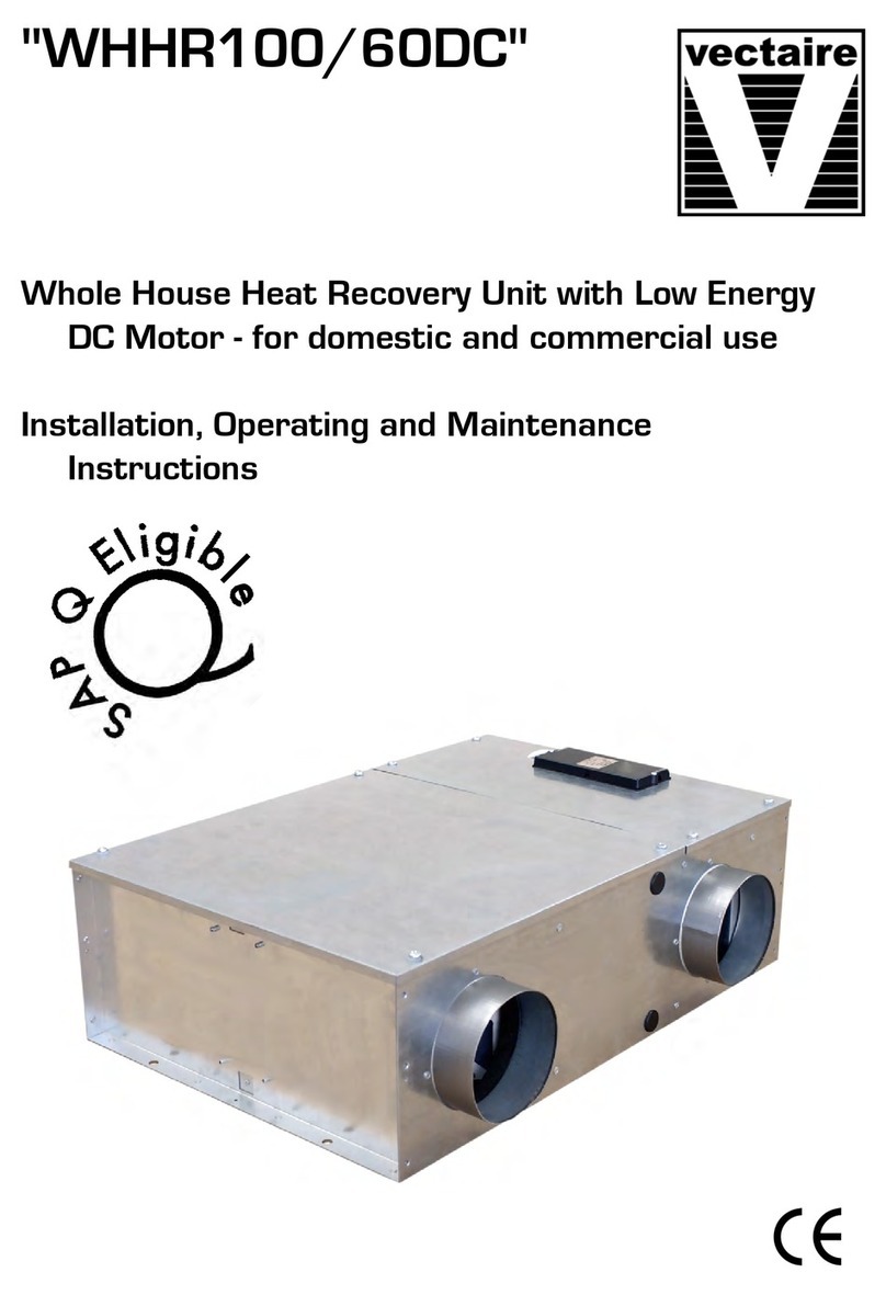
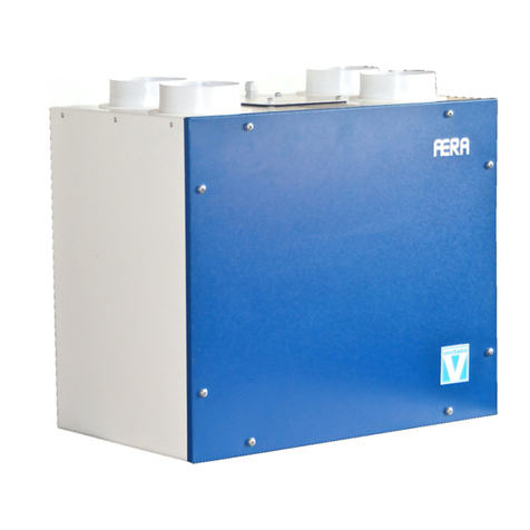
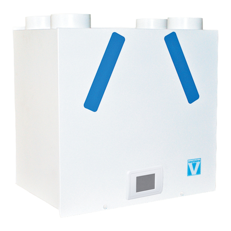
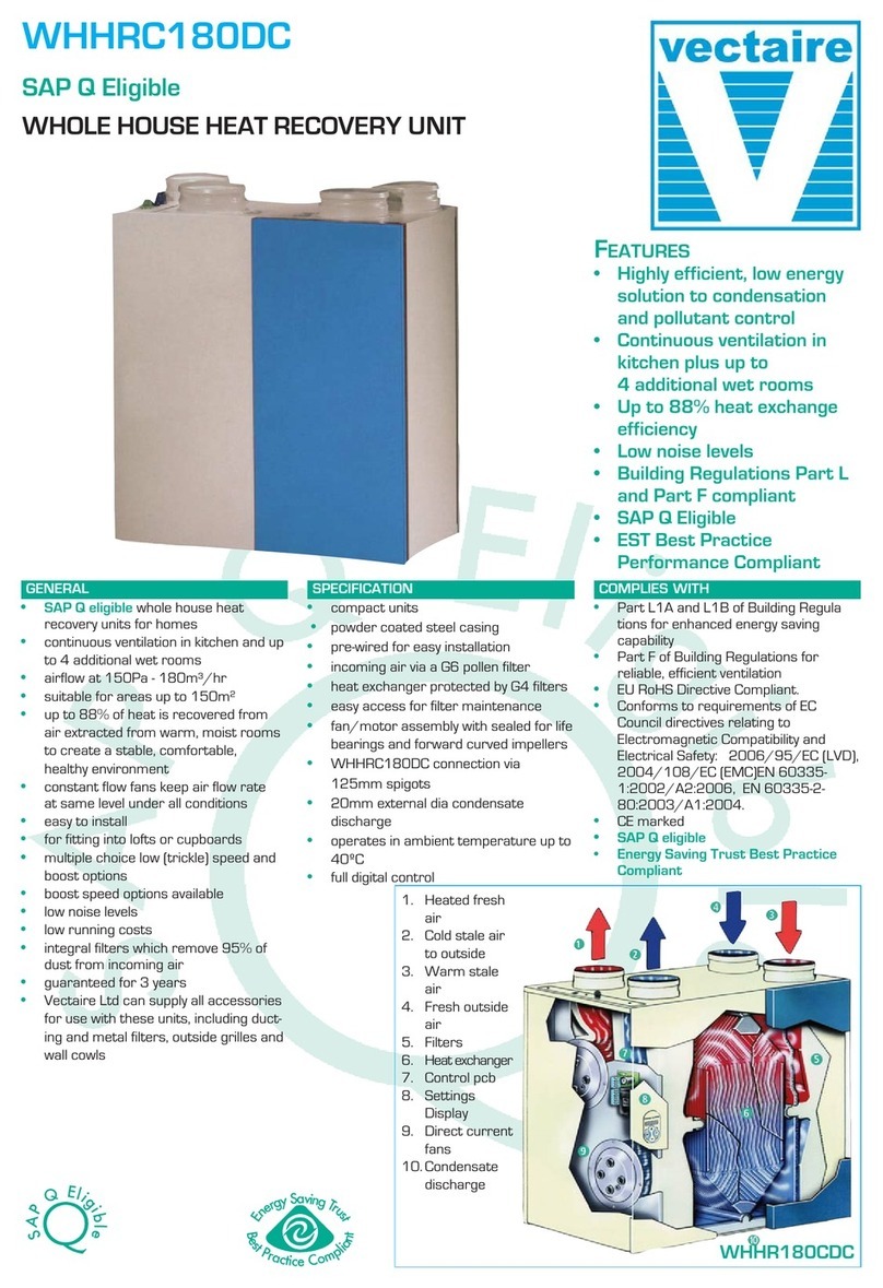
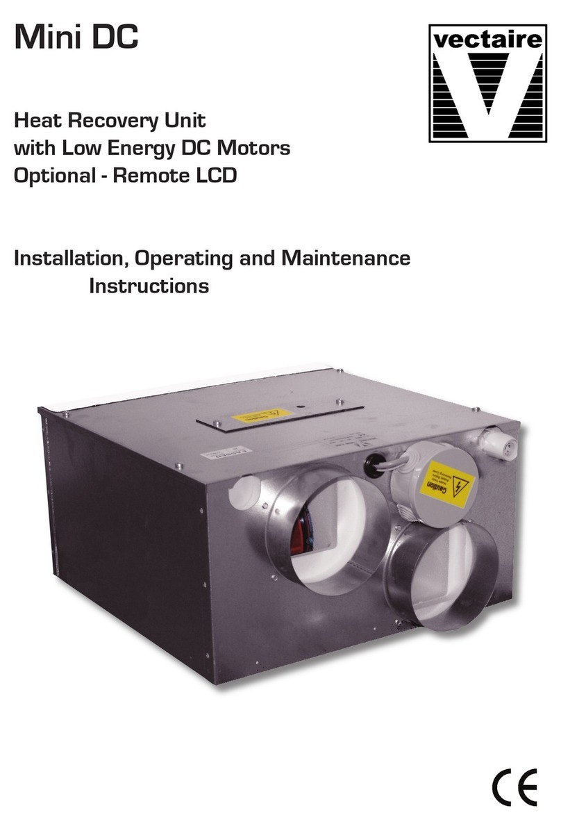
• 4 x 125mm spigots are provided for the connection of ducting. These are c ear y marked for correct connection of the
supp y and exhaust ducts.
• Where ducting is insta ed in an unheated space, a of the ducts shou d be insu ated. Where ducting is in sta ed in a heated
space, on y the co d ducts shou d be insu ated. i.e. the supp y duct from outside and the extract duct from the unit to the
outside.
• The duct ayout must be designed to suit the requirements of the venti ation/recovery system and bui ding ayout. If the
ducting passes through a fire wa /barrier, suitab e fire dampers must be insta ed.
• Where rigid duct is used (preferab e), it shou d be insta ed using the east number of fittings to minimise air f ow resistance.
Where possib e, fina connection to the gri es and unit shou d be made with a f exib e connection.
• Where f exib e ducts are used, ensure that:
- duct runs are kept as short as possib e
- the duct is stretched so that it is smooth and straight
- where bends are necessary, they have arge radii (ie avoid sharp bends)
- the duct is not crushed if in a restricted area
Condensation
(The unit may sometimes produce condensation which must be drained away. A 15mm dia pipe connection is provided on
this unit).
•A 15mm dia pipe must be fitted to the pipe connection. If any part of the condensate drain is in an unheated space it
MUST be insu ated with the equiva ent of at east 25mm of insu ating materia with a therma conductivity of 0.04 W/(mK).
•The pipe must drain into the norma househo d drainage system.
•The drain must incorporate a wet or dry trap to prevent air penetration.
•The unit must be ti ted towards the side carrying the condensation exit point. It shou d be insta ed horizonta y with a
3º ti t towards the condensation drain used (equiva ent of raising the opposite end by approximate y 30mm).
•The drainage pipe must have a continuous fa from the unit to the drainage co ection point.
E ectrica Connection
WARNING: these app iances must be earthed and a wiring must conform to current IEE Regu ations and a app icab e
standards and Bui ding Regu ations.
• The unit is suitab e for 230v-240v, 50Hz: Consumption - 0.92Amps
• The unit is supp ied with:
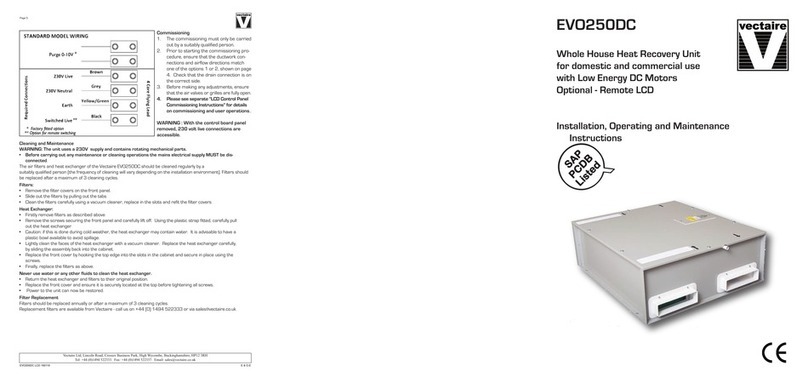
- A mains rated 4 core f exib e cord (b ack, brown, grey, green/ye ow)
- An optiona factory-fitted 2 cord vo t-free f exib e cord for purge switching
• A trip e po e iso ation switch with contact separation of at east 3mm must be used to connect the app iance to the
fixed wiring when using the Switched Live.
• Boost contro s must not be ocated within 1 metre of a cooker or where they may be affected by excessive heat or
moisture
• Boost contro s shou d be c ear y identified and convenient y ocated.
• The boost switch wiring cab e access is via a 12mm cab e g and.
• The boost speed can be activated by a switched ive connection from a variety of externa devices inc uding:
- PIRFF (passive infra red)*
- DRH240 (dynamic remote humidistat)*
- THM (thermostat)*
- a ight switch (if more than one ight switch is used, each one must be a doub e po e switch)
- a remote switch/pu cord
or via LCD contro pane
(*PIRFF, DRH240 and THM may have integra over-run timer which contro s the ength of time that the fan wi continue to
operate at its boost speed after the boost has been switched off.)
Commissioning
•When the unit is set up and running, the minimum setting on the speed contro switch must re ate to the designed vo ume
air f ow. The variab e air f ow from minimum to maximum a ows the unit to extract a greater vo ume to cope with any in
crease in the bui d up of condensation or fou air, ie cooking etc.
•Before starting the commissioning procedure, refer to the design drawing for correct air f ows.
•Insta ation of the app iance MUST be carried out by a qua ified and suitab y competent person and shou d be carried out
in c ean, dry conditions where dust and humidity are at minima eve s. It shou d on y be insta ed after other bui ding works
have been comp eted and the bui ding in which it is insta ed c eaned. Fai ure to comp y with any of the above points wi have
an impact on the va idity of the guarantee.
•Prior to starting the commissioning procedure, ensure that the ductwork connections and airf ow directions are as marked
on the product.
•Before making any adjustments, ensure that the air va ves or gri es are fu y open.
• P ease see separate "LCD Contro Pane Insta er Instructions" for detai s on commissioning and user
operations.
WARNING : With the contro board pane removed, 230 vo t ive connections are accessib e.
Page 4
