GB RKB Series User manual

MIUM0001_REV01_ RKB_20140130 MIUM ENG.docx
1
I
IN
NS
ST
TA
AL
LL
LA
AT
TI
IO
ON
N,
,
O
OP
PE
ER
RA
AT
TI
IO
ON
N
A
AN
ND
D
M
MA
AI
IN
NT
TE
EN
NA
AN
NC
CE
E
M
MA
AN
NU
UA
AL
L
50% EFFICIENCY AIR TO AIR HEAT RECOVERY
UNIT
SERIES RKB
MIUM0001_REV01_ RKB_20140130 MIUM ENG.docx
2
Dear Customer,
Thank you for having purchased an LMF product. It is the result of many years of experience, research and has been
made with top quality materials and highly advanced technologies. The CE mark guarantees that the machine meets the
European Standards regarding safety.
The qualitative level is kept under constant surveillance. LMF products therefore offer SAFETY, QUALITY and
RELIABILITY.
Thank you once again for your preference.
The manufacturer declines all responsibility for any inaccuracies in this manual due to printing or typing errors.
The manufacturer reserves the right to modify the products contents in this catalogue without previous notice.
DECLARATION OF CONFORMITY
The Legal Representative of LMF S.p.A., located in Meledo di Sarego, via Paradiso 33 (Vicenza- ITALY), declares that
the unit belonging to RKBseries complies to the prescriptions of the Machine Directive 2006/42/CE, Low Voltage
Directive 2006/95/CE, EMC Directive 2004/108/CE and Ecodesign Directive 2009/125/CE.
The unit belonging to the above series is designed according to the following main safety prescriptions:
- principals of safety integration;
- used materials free from risk;
- safety while transportation, handling and installation;
- protection against mechanical risks;
- protection against electrical risks;
- protection against fire risks;
- design and construction done so that noise emission is reduced to minimum level;
- protection against the risk to remain trapped inside the machine;
- CE indelible marking complete with the needed indications;
- supply of an “User manual”
DECLARATION OF INCORPORATION
(Directive 2006/42/CE –Annex II paragraph B)
Moreover, the Legal Representative of LMF S.p.A. declares that the above machine shall be correctly installed and used
and the system itself that integrates the machine shall be certified according to the prescriptions of the above Machine
Directive 2006/42/CE.
Finally, he declares that the physical person authorized to the management of the Technical File is Mr. Michele Mattiolo,
c/o LMF S.p.A., via Paradiso 33, Meledo di Sarego (Vicenza - ITALY).
Meledo di Sarego (VI)
01/01/2013 The Legal Representative
Ferraro Mauro
MIUM0001_REV01_ RKB_20140130 MIUM ENG.docx
3
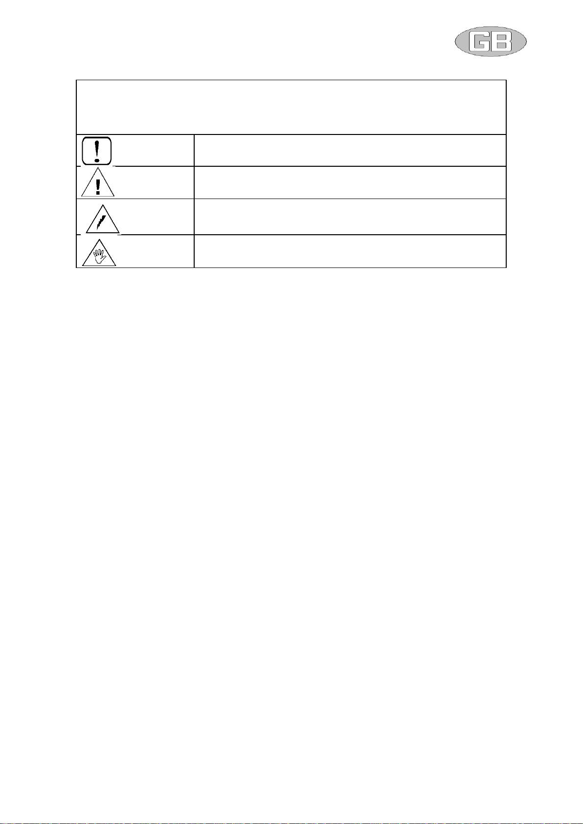
SYMBOLOGY
ATTENTION
DANGER
HIGHRISK OF ELECTRIC SHOCK
ATTENTION: AUTHORIZED PERSONNEL ONLY
1–INTRODUCTION
pag. 4
2-DIMENSIONS AND WEIGHTS
pag. 5
3–INSTALLATION CONFIGURATIONS
pag. 6
4–TRANSPORTATION
pag. 7
5–INSTALLATION &CONNECTION
pag. 8
6–WIRING DIAGRAMS
pag. 10
7–STANDARD MAINTENANCE
pag. 11
8–TROUBLESHOOTING
pag. 12
9–MATERIAL DISPOSAL
pag. 12
MIUM0001_REV01_ RKB_20140130 MIUM ENG.docx
4
1-INTRODUCTION
Dear Customer,
these heat recovery units are designed and developed for residential and commercial applications and allow the room air
renewal with a sure energy saving. Unit must be used only for this purpose, LMF will not respond in case of different use
of the unit.
In fact, where the room air renewal is needed, the unit transfers heat between the exhaust air to the fresh air that
otherwise would be lost.
In their basic working principle, they consist in (see figure 1) :
1 –fans (supply and exhaust air)
2 –counterflow heat recovery
3 –filter sections (on fresh air and return air intakes)
4 –electrical board
These units may be integrated with traditional heating and cooling systems, but they can operate also autonomously if
equipped with the proper accessories.
• This manual and the wiring diagram supplied with the unit must be kept in a dry place and ready to hand for future
consultation when required.
• This manual has been compiled to ensure that the unit is installed in the correct way and to supply comprehensive
information about how to correctly use and service the appliance. Before proceeding with the installation phase,
please carefully read all the information in this manual, which describes the procedures required to correctly
install and use the unit.
• Strictly comply with the instructions in this manual and conform to the current safety standards.
• The appliance must be installed in accordance with the laws in force in the country in which the unit is installed.
• Unauthorized tampering with the electrical and mechanical equipment will VOID THE WARRANTY.
• Check the electrical specifications on the identification plate before making the electrical connections. Read the
instructions in the specific section where the electrical connections are described.
•If the unit must be repaired for any reason, this must only be done by a specialized assistance center recognized by the
manufacturer and using genuine spare parts.
• The manufacturer also declines all liability for any damage to persons or property deriving from failure of the information
in this manual to correspond to the actual machine in your possession.
• Proper uses: this series of air to air heat recovery unit is designed to air renewal/conditioning purposes. Any
use differing from this proper use or beyond the operating limits indicated in this manual is forbidden unless
previously agreed with the manufacturer.
• The prevention of the risk of fire/injury at the installation site is the
responsibility of the end user and/or installer.
Verify, upon acquisition, that the apparatus is complete and supplied as
described.
Any eventual disputes must be presented in writing within 8 days from the
reception of the goods.
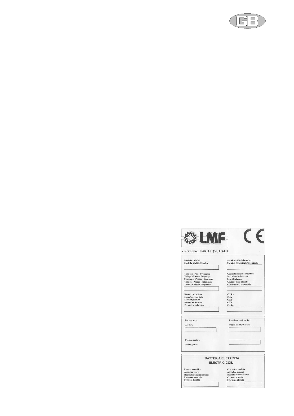
Each unit is provided with identification plate listing the following:
-Address of Manufacturer
-“CE” Mark
-Model
-Serial Number
-Power supply voltage in “V”
-Power supply frequency in “Hz”
-Number of phases indicated with “Ph”
-Maximum current in “A”
-Date of fabrication
-Code
-Motor power “W”
-Absorbed power “kW” of electric coil (if present)
-Absorbed current “A” of electric coil (if present)
MIUM0001_REV01_ RKB_20140130 MIUM ENG.docx
5
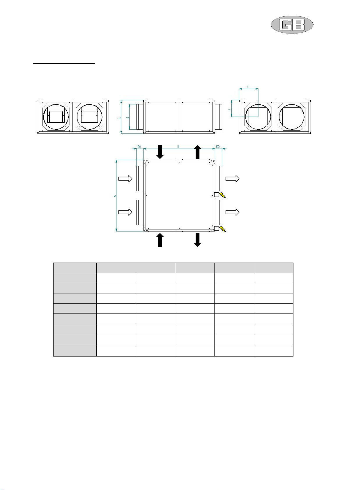
2–DIMENSIONS AND WEIGHTS
Packing dimensions
The following table, referred to the figure, shows the characteristic dimensions of the horizontal series RKB.
M = Supply, E = Exhaust, R = Return A = Fresh air
RKB
500
1000
2000
3000
4000
A (mm)
750
900
1000
1300
1400
B (mm)
750
900
1000
1300
1400
C (mm)
290
410
470
530
705
D Ø (mm)
200
315
355
450
500
E (mm)
145
205
235
265
352
F (mm)
202
240
265
340
365
Ø condensate
(mm)
2 x 1/2" F
2 x 1/2" F
2 x 1/2" F
2 x 1/2" F
2 x 1/2" F
Weight (kg)
41
68
99
155
235
E90
R90
A90
E
M
A
R
M90
MIUM0001_REV01_ RKB_20140130 MIUM ENG.docx
6
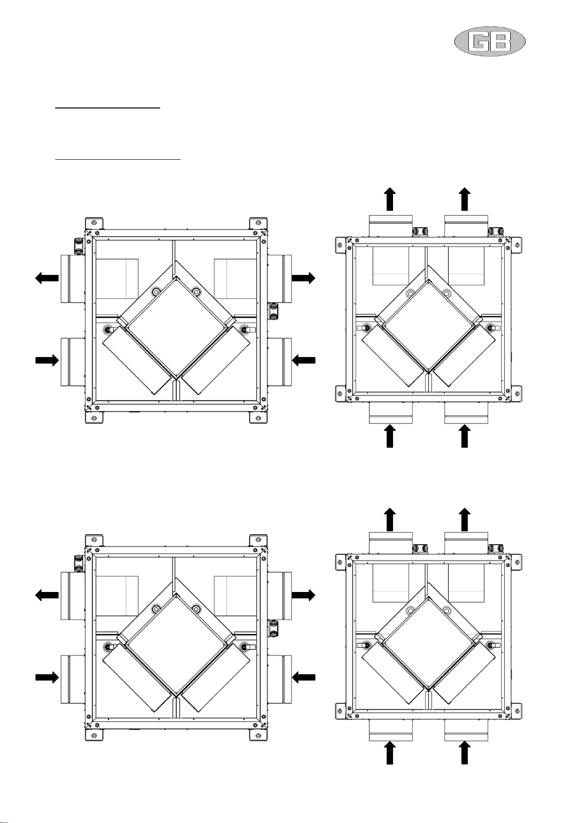
3–INSTALLATION CONFIGURATIONS
Possible positioning
According to the air duct layout, it is possible to rotate adequately the RKB unit air inlets and outlets to give the following
combinations, each of them is a specific unit orientation to be specified when ordering.
Horizontal configuration RKB
Configurations shown on the figure below are possible.
(A = fresh air, R = return air, M = supply air, E = exhaust air)
TYPE “A”
Configurations shown on the figure below are possible.
(A = fresh air, R = return air, M = supply air, E = exhaust air)
TYPE “B”
M90
E
A
M
R
E90
R90
A90
M
R
E
A
A90
R90
E90
M90

MIUM0001_REV01_ RKB_20140130 MIUM ENG.docx
7
Thanks to the double drain pan type “A” and type “B” can easily exchangeable on site, no modification has to be done.
To modify the position of the each inlet/outlet panels (for example from “E” to “E90”you may need to exchange two
panels between each other.
Vertical configuration RKB + vertical kit
Configurations shown on the figure below are possible.
(A = fresh air, R = return air, M = supply air, E = exhaust air)
TYPE “A”
TYPE “B”
To modify the position of the suction inlets it is sufficient to exchange two panels each other.
A
R
E
M
M90
M90
A
R
E
M
E90
E90

MIUM0001_REV01_ RKB_20140130 MIUM ENG.docx
8
4–TRANSPORTATION,HANDLING AND STORAGE
Packaging
Each unit is put on bench and protected with cellophane film; the protection must remain intact until the moment of
installation.
The materials that are not mounted for technical motives are supplied in fitted packing fixed externally or internally to the
unit.
Recycle and dispose of packing material in conformity with local regulations, be extremely careful not to damage the unit.
Handling
Comply with the current safety regulations concerning the equipment to use when handling the unit or the required ways
of operating. Use single protection devices as goggles, gloves, helmets… when handling the unit to avoid risk of injuries.
For the lifting and transportation of the unit, use adequate equipment, according to the 89/391/CEE regulations and
further modifications.
Each individual unit weight is listed in this manual.
While moving, try to avoid rotation without control.
Check the weight of the unit before proceeding with the moving and handling operations. Make sure that the appliance is
handled with care and without jolting as rough treatment could damage the functional parts
of the machine. To safeguard persons and property, read the information on the packing that covers the unit before
handling.
Also make sure to:
• Handle the machine with care
• Do not stack other objects on top of the unit
Before positioning please consider the overall dimensions and the technical space requirements of the system and the
unit, electric and hydraulic connections and any air pipes/ducts or free passages.
Neglecting these aspects may decrease performance and operational life of the unit and therefore increase the operating
costs and maintenance.
Units are designed to be installed INSIDE or PARTIALLY OUTSIDE (roof cover needed) and in fixed positions.
Before placing the unit be sure that:
• the location is in a safe accessible place
• the framework or the floor or ceiling is adequate to support the weight of the unit, please refer to weight paragraph
• support points are leveled and aligned
• the place can not be subject to flooding
• the maximum level of the snow does not obstruct the airflow to the unit
To ensure the best air circulation to the unit and thus ensure a smooth operation it is recommended to:
•avoid obstructions to air flow near or above the unit
• protect the unit from high winds that can favor or not the airflow
• protect the unit from heat sources or pollutants (chimneys, extractors…)
• protect the unit from air stratification or recirculation (avoid bad ducting of the fans, containment structure, high walls or
corners next to the unit)
These advises if not respected can lead to a lower efficiency of the unit and possible failures.
Checklist
Upon reception of the unit, we suggest that a complete control is carried out, to verify that the unit is intact and complete,
and no damage has been sustained during transport. Any eventual damage revealed must be communicated to the
carrier, demonstrating the reserve clause within the transport documents, specifying the type of damage.
Storage
The units must be stored in a dry place, sheltered from the sun, rain, sand and wind.
Comply with the storage conditions given below:

MIUM0001_REV01_ RKB_20140130 MIUM ENG.docx
9
• Do not stack the units
• Maximum temperature = 60°C
• Minimum temperature = -20°C
The Manufacturer declines any responsibility for any damage as a result of negligence or lack of protection from
atmospheric agents.
5–INSTALLATION &CONNECTIONS
Definitions
CUSTOMER –The Customer is the person, activity or the society, that has bought or hired the unit, and intends to utilize
the machinery for its intended use.
USER / OPERATOR –The User or Operator is the actual person that has been authorized by the Customer to utilize the
unit.
QUALIFIED PERSONNEL - Defined as the person who has followed a relevant specific course of study, and so is able
to understand the dangers derived from the use of the machinery, and in turn, due to this, are capable of solving major
dilemmas.
Safety regulations
Qualified personnel must carry out the installation.
During the installation operation, use protective clothing, for example: glasses, gloves, etc. as indicated by
686/89/CEE and successive regulations.
During the installation operate in absolute security, pollution free air and in an area free of obstructions.
Respect the regulations in force in the country in which the apparatus is being installed. Specifically relative to
its use, and to the disposal of packing and products used for the cleaning and maintenance of the unit. Respect
the recommendations given by the producers of such products.
Before placing in function the unit, check the perfect connection of the various components and the internal
parts of the system.
Avoid at all costs human contact with moving parts and contact with the parts themselves.
Do not commence with servicing or cleaning of the unit, before the unit has been disconnected from the
main supply.
The maintenance and the substitution of damaged or consumed parts must be carried out only by specialized
personnel, following the indications found within this manual.
Spare parts must correspond to the requirements specified by Manufacturer.
In case of dismantling of the unit, respect the anti-pollution regulations in force.
N.B. The installer and the user of the apparatus must take into account, and solve problems, connected with any other
type of risk that may occur to the unit. For example, risks derived from the entrance of foreign bodies, or risks due to the
presence of flammable or toxic gas.
Preliminary operations
Check the perfect condition of the various components of the unit.
Control that contained within the packing, there are the installation accessories, and documentation.
Transport the packed section as close as is possible to the intended place of installation.
Do not place tools or weight on top of the packed unit.
The Manufacturer declines any responsibility for failure to respect the Safety Regulations and the prevention
as described below.
Furthermore, the Manufacturer declines any responsibility for damage caused by the improper use of the unit
and/or modifications carried out without proper authorisation.
MIUM0001_REV01_ RKB_20140130 MIUM ENG.docx
10
Choosing place of installation
Position the unit on a solid structure, that will not vibrate, and is capable supporting the weight of the machine.
Position the unit in a point where the condensation discharge may occur easily.
Do not position the unit in an area in which flammable gases, acidic or corrosive substances are present. They
may damage various components in an irreparable manner.
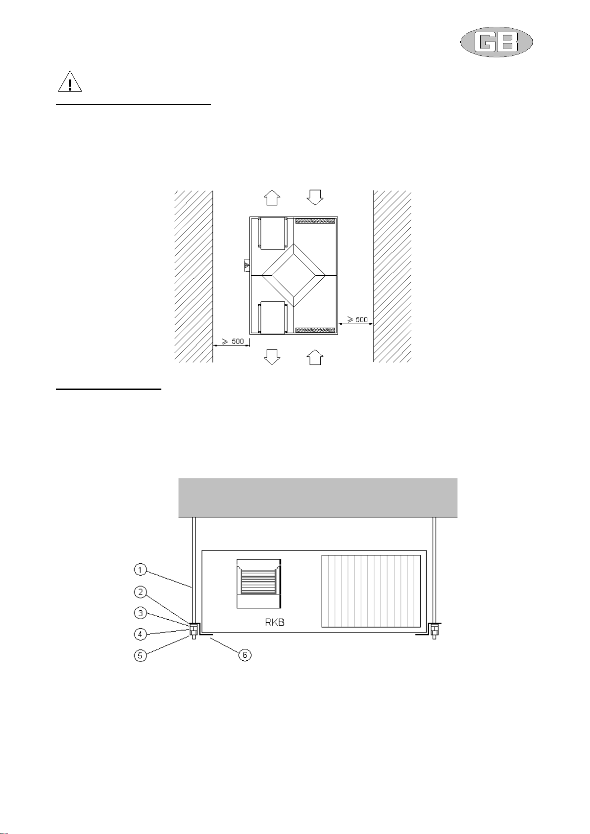
Allow a minimum amount of free space as indicated in the following figure. This permits ease of installation and
maintenance.
Machine positioning
The unit is equipped with anti-vibration support plates.
Referring to the following figure, the following are instructions to fix the unit to its supports :
1. Carry out the drilling of the ceiling, and fit the four M8 threaded bolts (1).
2. Position the unit on the four bolts using the supplied fixing plates (6).
3. Insert antivibrating (2), washer (3) and screw nut (4) and lock nut (5) without blocking.
4. Install the unit with 3 mm inclination towards the condensate outlet to aid the condensation going out.
5. Block the unit tightening the fixing bolts.
MIUM0001_REV01_ RKB_20140130 MIUM ENG.docx
11
Air duct connections
The ducts must be the correct dimension based on the functions of system and the air diffusion characteristics
of the unit fans.
To prevent the formation of condensation and cut down the sound level it is advised to use internally lined
ducts.
To avoid the transmission of unit vibrations into the environment, it is advised to fit an antivibrating joint between
the fans and ducts. The electrical continuity must be guaranteed between the ducts and the apparatus via an
earth cable.
Water connections
The installation and connecting of the piping is an operation that must be done correctly, otherwise it may compromise
the performance of the system. At worst it may cause irreversible damage to the machine. These operations are to be
effectuated by qualified personnel.
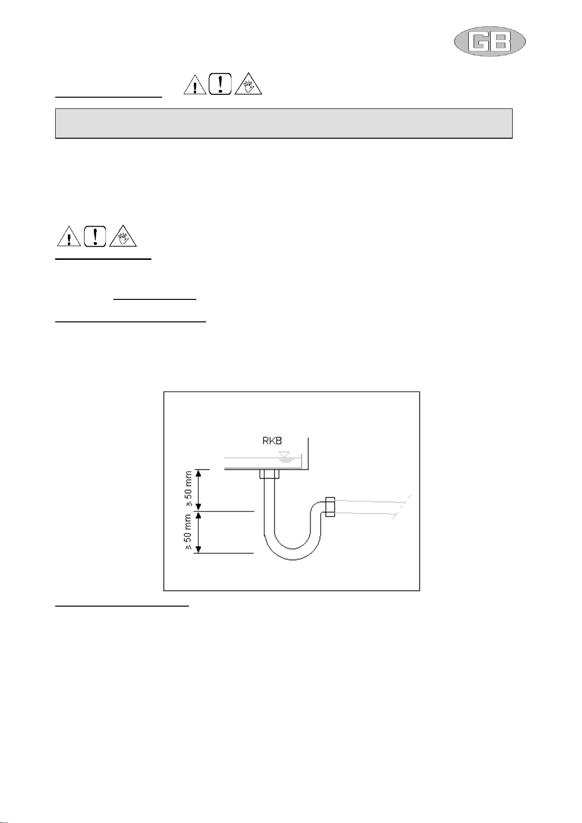
Condensation outlet connection
The system of drainage must provide an adequate trap able to allow the condensation run off on under pressure
conditions.
The trap must be designed as shown on the following figure
The trap must have a tap for correct cleaning of the lower part, and must allow an easy disassembly.
The path of the condensation drainage tube must always have a gradient toward external.
Insure that the condensation run-off tube does not interfere with discharge of the unit.
Water coil connection (SAF)
The water heating or cooling coil (SAF) is supplied with GAS “male” threaded headers.
The tightening must be carried out with extreme care to avoid damage to the copper collectors of the coil.
The path of the tubes must be studied in a way to avoid obstacles should it be necessary to extract the unit coil.
Inlet and outlet water must consent the thermal exchange against the current. Follow instructions found on the
WATER INLET and WATER OUTLET plate.
Provide an air valve at the top of the unit, and a water discharge valve at the bottom.
Reinforce sufficiently the units external tubes to avoid offloading the weight onto the coil.
Once connection has been effectuated, fix the external seal flush against the control panel, in this way avoiding
the passing of air.
The insulation must not rest against the paneling, as this may provoke burning.
For control purposes, organize the interception of the tube side coil when the fan is off, to avoid internal
overheating and possible damage to internal components.
Provide an anti-freeze system.
Provide a cut out switch to isolate the coil from the rest of the circuit in case of extensive maintenance needs.
Should the unit be installed in particularly cold areas, drain completely before plant shut-off long periods.
IMPORTANT: IT IS IMPORTANT NOT TO PLACE IN OPERATION THE UNIT IF THE FAN OUTLETS ARE
NOT DUCTED OR NOT PROTECTED BY A SAFETY NET ACCORDING TO THE ACTAUL REGULATION.
MIUM0001_REV01_ RKB_20140130 MIUM ENG.docx
12
Electrical connections
Qualified personnel according to the supplied schemes must carry out the electrical connections at the control
panel.
Insure that the voltage and the frequency shown on the technical plate correspond to the connecting power
supply.
For the general power supply of the unit, and its accessories, the use of adapters, multiple plugs and extension
leads is to be avoided.
It is the responsibility of the installer to insure that the installation of the unit is as close as possible to
the mains power supply, or sufficiently close to protect the electrical parts.
Connect the unit to an efficient power point, using the correct screws as supplied with the unit.
In the unit with relay board the screws of the connectors must be screwed with torx equal to 0,5 Nm
6–WIRING DIAGRAMS
Follow wiring diagram attached to every unit as a sticker inside the electrical plastic box.
For connection the unit to accessory LVN (relay power box), RCV (3 step fan speed control) and CVU (step fan speed
selector), please see the diagrams attached to the unit.
7–STANDARD MAINTENANCE
It is the responsibility of the User to carry out all types of maintenance operations.
Only personnel previously trained and qualified may carry out maintenance operations.
Should the unit require disassembly, hand protection is required
Maintenance is of extreme importance if the plant is to operate in a regular way and give fade-free service. Have
maintenance work done by qualified and authorized personnel, according to EU Regulation 303/2008 of 2 April 2008
(and later) that requires companies and technicians that perform maintenance / repair, leakage checking and recovery /
recycling gases must be certified as required by local regulations. Comply with the safety precautions given in the
relative section of this manual and take all the necessary precautions. The following information is only a guide for the
end user.
Maintenance keeps unit efficiency, reduce the speed of deterioration over time and collect information and data to
understand the efficiency of the unit and prevent failures. We suggest to prepare a booklet of installation according
European legislation. Provide a machine book that allows you to track of the actions taken on the unit, so it will be easier
to cadence adequately the various interventions and will facilitate a possible troubleshooting.
Please take note of: date, type of action, description of action, measurements performed, anomalies identified, alarms
registered in the alarm history, etc. ...
Before starting any operation, insure that the general power supply has been isolated.
All the electrical connections must be protected at the source by the installer.
Follow the connection of the unit and its accessories using adequate cabling for the power used, and
respecting the country regulations. The dimensions of the cabling must be sufficient to support a
voltage drop in start up phase inferior to 3% of the nominal.
BEFORE FOLLOWING ANY TYPE OF MAINTENANCE OPERATION, BE CERTAIN THAT THE UNIT MAY NOT
CASUALLY OR ACCIDENTALLY BE CONNECTED TO THE ELECTRICAL MAINS SUPPLY. THERFORE IT IS
NECESSARY TO SHUTDOWN THE UNIT’S POWER SUPPLY AD PRIOR TO MAINTENANCE.

MIUM0001_REV01_ RKB_20140130 MIUM ENG.docx
13
Monthly maintenance
Air filters
Filter section can be entered through bottom panel; dismounting it the filter can be extracted.
For the cleaning, utilize a vacuum cleaner or wash with normal detergent and warm water, allow to dry well. Remember
to assemble the filter before operating the unit; replace a new filter after max 3 cleaning cycles. In case of soft bag filter
(option), replace it when dirty.
Condensation discharge
Remove side panel and clean, if necessary, the dirt and impurities that have formed in the condensation tray. Also check
the efficiency of the trap.
Water coil
Check that the coil exchanger (optional) is clean and in perfect state to guarantee the normal levels of performance.
Yearly maintenance
Check that all the electrical equipment, in particular the fixing of the electrical connections.
Check the tightness of all nut, bolts, flanges and hydraulic connections that the vibrations of the machine may have
loosened.
8–TROUBLESHOOTING
Failure searching and problem solving schedule
Founded failure
Probable cause
Possible solution
Fans are not running
Power supply is switched off
Wrong or loose electrical
connections
Motors on thermal protection mode
Switch on the power supply
Restore the right connections
Check motor current
Air performance decreasing
Air filter dirty
Air duct blocked
Clean or replace filter
Check air system (are dampers
open ?)
Condensate water stays inside the
unit
Condensate drainage blocked
Missing or not adequate trap
Clean or free the drainage
Install a right trap
9–MATERIAL DISPOSAL
At the end of unit’s lifetime, its components must be dismantled and disposed of respecting the operational regulations
present in its country of installation.
The materials that the unit is constructed of are:
-Precoated galvanized steel sheet metal
-Galvanized steel sheet metal
-Aluminum
-Copper
-Polyester
-Polyethylene
-Glass wool
-Plastic
During disconnection of the unit, avoid gas leakage or liquid spillage on environment, especially if the water has additives
like glycol. For dismissing and disposal, deliver the units to specialized centers according to your national laws.
This manual suits for next models
5
Table of contents
Popular Heating System manuals by other brands


flamco
flamco Duo Installation and operating instructions

Rotex
Rotex Solaris OPERATING AND INSTALLATION Manual

PAW
PAW HeatBloc MC42 Installation and operation instructions

Aqua-Hot
Aqua-Hot 400 series Use and care guide

Viessmann
Viessmann Solar-Divicon-HX specification

Kroll
Kroll HM200 Instruction handbook

Carrier
Carrier FB4CNF installation instructions

Dimplex
Dimplex DWF1203 troubleshooting guide

Palazzetti
Palazzetti ECOMONOBLOCCO MX User and maintenance manual

Immergas
Immergas SUPER TRIO Instructions Booklet and warnings

Salda
Salda RIS 700 V EKO 3.0 MOUNTING AND INSTALLATION INSTRUCTION

Daikin
Daikin ALTHERMA Installer's reference guide