1 2
3 4
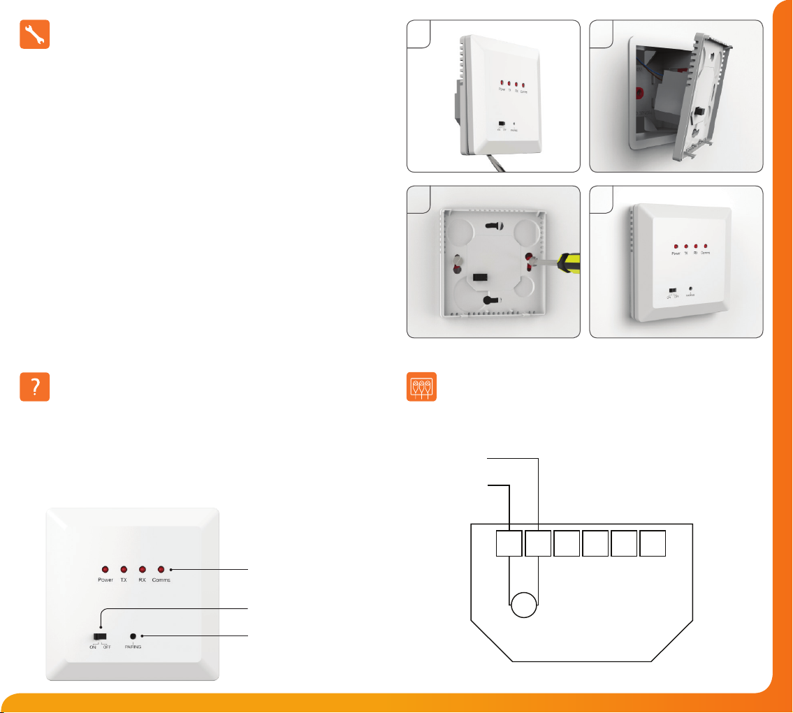
Installation Procedure
This repeater is designed to be ush mounted and requires a back box of 35mm
(minimum depth) to be sunk into the wall prior to installation.
Step 1
Carefully separate the front half of the repeater from the back plate by placing a
small at head terminal driver into the slots on the bottom face of the repeater.
Step 2
Place the repeater front somewhere safe.
Terminate the time clock as shown in the wiring diagram.
Step 3
Screw the repeater back plate securely into the back box.
Step 4
Clip the front of the repeater back onto the repeater back plate.
Please read the instructions fully so you get the best from our product.
LED Status Wiring Diagram - WR1
Power Switch
Pairing Button
There are 4 LED lights on the repeater.
Power LED - Permanently on when the WR1 is powered.
TX LED - Flashes when signal received.
RX LED - Flashes when boosting signal to the receiver.
Comms - O under normal operation.
Each LED is labelled and will light up or ash during operation.
Comms LED
230VAC
WR1
L N
Live
Neutral
Mains Supply In
Recommendations
Max Cable Size - 1.5mm
Back Box Depth - 35mm


