HeatPumps4Pools iFlo Junior User manual
Instruction Manual
iFlo Junior Filter Pump

8
Important information!
Read these instructions carefully before commencing assembly.
Please ask your specialist retailer for further information or advice on filters, water maintenance
and accessories.
We reserve the right to make changes to the product specification and design without advance
notification within the context of further technical development.
This device is not designed for persons (including children) with limited physical, sensory or mental
capabilities, or who lack the required experience and/or knowledge, unless they are supervised by
a person responsible for their safety or have received instructions from them about how the device
should be used.
Children must be supervised by an adult at all times to ensure they do not play with the device.
Installation and assembly instructions
You have purchased a simple and easy-to-use device. However, you must follow certain rules and
regulations to ensure its safe and correct application. Therefore, please read the following instruc-
tions carefully before use!
A skimmer is required for filter system operation, i.e. either an integrated skimmer (installation in
the steel wall) or an inserted skimmer (attachment to the steel wall).
Caution! Safety instructions for the use of electrical equipment
1. Electrical installation must be carried out by a licensed electrician. The supply line must
beprotected by a residual current circuit breaker 30 mA. Make sure all connections are correct
and carried out in accordance with local codes (VDE regulations). We shall not be liable for the
consequences resulting from incorrect installation, start-up and electrical installation.
2. Do not bury the pre-wired connecting cable.
3. Make sure that the connecting cable cannot be damaged (by a lawnmower, grass strimmer,
etc.). Replace a damaged connecting cable IMMEDIATELY.
4. Children must be supervised by an adult at all times when in the vicinity of the filter system!
5. Never use the filter system if people are actually in the swimming pool.
If damaged, the connecting cable must be replaced immediately by an appropriately trained
and qualified person to prevent the risk of injuries.
Installation location
Install the filter system between the skimmer and the injection nozzle, ensuring sufficient clea-
rance to the wall of the pool.
We recommend you to place the filter system on level concrete slabs, etc. Use a spirit level to ensu-
re the slabs are completely level.
Never install the filter system on low-lying ground or directly on a lawn (risk of flooding or over-
heating of the filter pump).
If your pool is a fully or partially in-ground pool, it makes sense to install the filter system in a filter
shaft right next to the pool.
If the filter system is installed in a filter shaft, make sure the shaft cannot flood. It is recommended
to place a layer of pebbles or gravel around the filter shaft to allow existing ambient water and
rainwater to drain freely. The ideal situation would be a direct connection to a drain in the sump
pit of the filter shaft (or a wet pit pump with a float switch).
Remember that the filter shaft should not be sealed air-tight, as this would result in condensation
damaging the filter pump. The filter shaft must be large enough to ensure convenient operation
or servicing of the filter system.
Any necessary accessories, such as hoses, hose clips and filter sand (not included), can be purchased
from your local swimming pool specialist.
GB
9
Assembling the filter system
Assemble the filter system at the desired location (transportation of the fully assembled filter
system to the installation point is not recommended!).
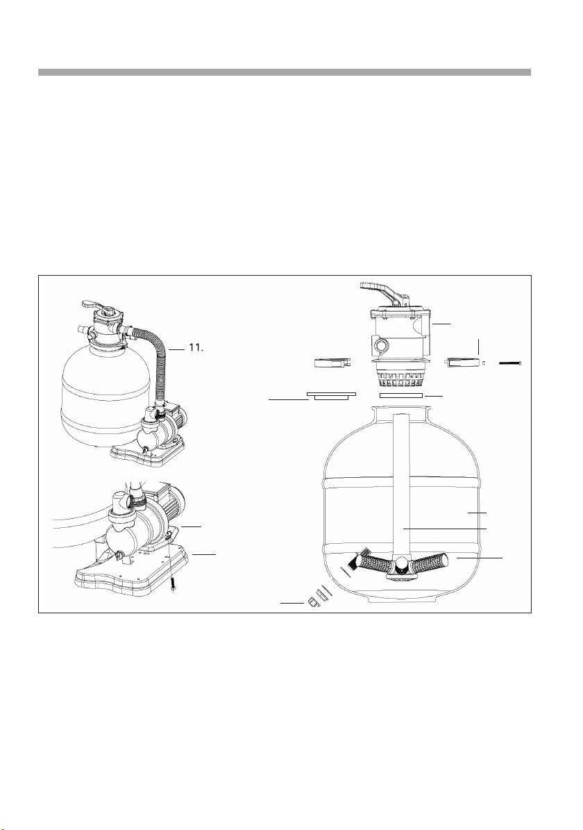
The filter pump consists of the following parts: (Fig. 1)
1. Pump
2. Valve
3. O-ring seal
4. Clamping ring
5. Filter tank
6. Centre pipe with lateral holder
7. Laterals
8. Drain plug
9. Neck fitting
10. Base plate
11. Pressure hose
9.
4.
3.
2.
10.
1.
5.
6.
7.
8.
Fig. 1
10
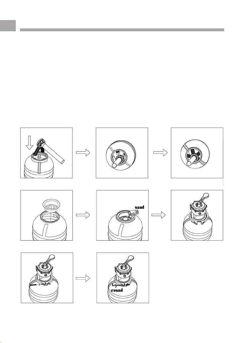
Filter tank
1. Insert the centre pipe including the lateral holder into the tank (Fig. 2) and screw the laterals
into the lateral holder (Fig. 3).
2. After assembling all the laterals, position the centre pipe with the lateral holder on the floor of
the tank. Make sure the centre pipe is positioned in the middle of the tank and that the drain
plug has been screwed in properly.
3. Now place the neck fitting on the tank opening, make sure the centre pipe is positioned in the
middle of the tank (Fig. 4).
tity: approx. 20 kg) (Fig. 4)
5. Now assemble the top of the filter tank (the valve head) and the filter seal on the rim of the
filter tank. Always remove any dirt, e.g. sand, in advance. Use the clamping ring to connect
the top of the filter tank (the valve head) to the filter tank. Use the nut and bolt to tighten the
clamping ring. (Fig. 5 and 6)
6. Finally, assemble the pump couplings at the valve head. Seal the pump couplings with suffici-
ent Teflon tape.
2
5
3a)
6a)
3b)
6b)
4a) 4b)
GB
4. Fill the filter tank approx. ¾ full with filter quartz sand. (Correct grain size: 0.4 – 1.2 mm; quan-
11
Filter tank
1. Insert the centre pipe including the lateral holder into the tank (Fig. 2) and screw the laterals
into the lateral holder (Fig. 3).
2. After assembling all the laterals, position the centre pipe with the lateral holder on the floor of
the tank. Make sure the centre pipe is positioned in the middle of the tank and that the drain
plug has been screwed in properly.
3. Now place the neck fitting on the tank opening, make sure the centre pipe is positioned in the
middle of the tank (Fig. 4).
4. Fill the filter tank approx. ¾ full with filter quartz sand. (Correct grain size: 0.7 – 1.2 mm; quan-
tity: approx. 20 kg) (Fig. 4)
5. Now assemble the top of the filter tank (the valve head) and the filter seal on the rim of the
filter tank. Always remove any dirt, e.g. sand, in advance. Use the clamping ring to connect
the top of the filter tank (the valve head) to the filter tank. Use the nut and bolt to tighten the
clamping ring. (Fig. 5 and 6)
6. Finally, assemble the pump couplings at the valve head. Seal the pump couplings with suffici-
ent Teflon tape.
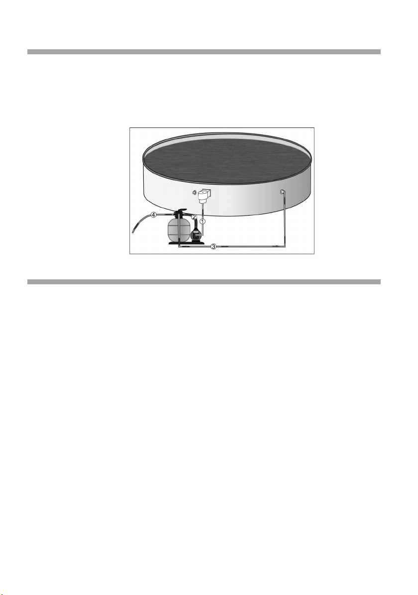
Hose connections (pump)
1. Skimmer line: Connection from the skimmer coupling to the front coupling at the filter system.
2. Pressure line: Connection from the upper coupling of the filter system to the “PUMP” coupling
at the 6-way valve.
3. Return line: Connection from the “RETURN” coupling at the 6-way valve to the coupling at the
injection nozzle (pool). Use hose clips to fix all the couplings into position.
4. Backwash: “WASTE” coupling into the drain. Connections are realised with special swimming
pool hoses and hose clips.
Starting up the filter system
1. Before starting up the filter system, make sure it is located outside the pool and positioned
below the level of the water in the pool. Also ensure that all the hose connections are secure.
2. Make sure the swimming pool has been filled with water according to the pool instructions.
The water must flow towards the filter pump.
3. The filter system is now de-aerated. If available, slightly open the pre-filter cover of the filter
pump until the water flows from the pre-filter bowl (transparent cover with threaded connec-
tion on the upper side of the filter pump).
4. Turn the 6-way valve handle to the BACKWASH position. This puts the filter pump into opera-
tion. Backwash for approx. 2 – 3 minutes. Subsequently switch off the filter pump and turn the
valve handle to the RINSE position. Rinse for approx. 30 seconds. Subsequently switch off the
filter pump and turn the valve handle to the FILTER position. It is best to feed backwash and
rinse water to the drain.
5. Switch on the filter pump. The filter system is in normal filter mode. We recommend you to
operate the filter twice a day for 4 – 5 hours. If you use a pool vacuum to clean the floor of the
pool, turn the valve handle to the FILTER position. Backwashing is necessary after using a pool
vacuum or if the pressure gauge reading (if available) rises by 2-3 scale marks.
6. RINSE for approx. 30 seconds after each BACKWASH. This helps to settle the sand in the filter
tank.
7. If you use a pool vacuum to clean the pool, you can also turn the 6-way valve handle to the
WASTE position in order to remove any impurities or dirt from the pool (e.g.: algae) which
would otherwise pass through the filter sand.
Caution! Do not operate filter systems without water!
The water acts as a coolant – warranty claims will not be accepted for filter systems
which have been operated without water!
Important information! Always switch off the filter pump before changing filter func-
tions at the valve head!
Equipped with either
a suction nozzle or a
skimmer Injection nozzle
12
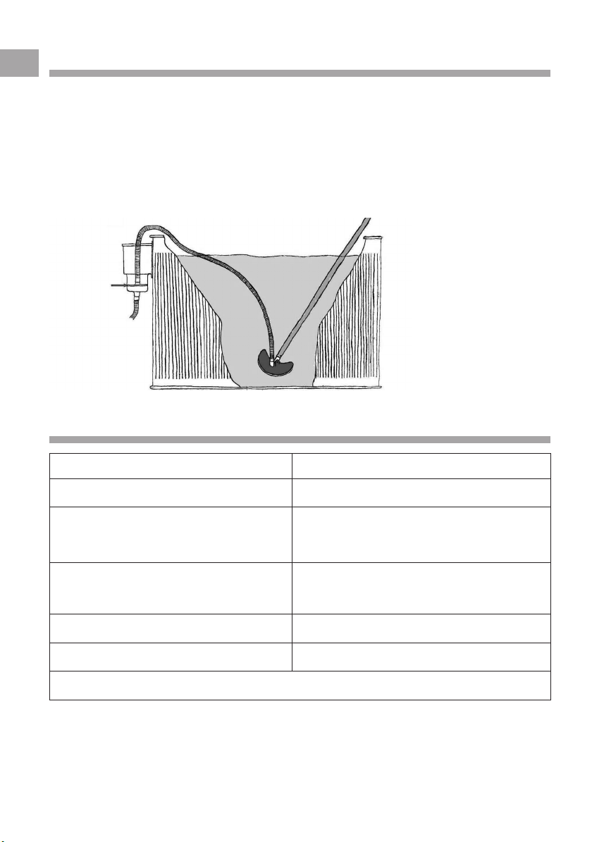
Vacuuming the floor of the pool
Turn the valve handle to the FILTER position when using a pool vacuum to clean the floor of the
pool. Connect the pool vacuum to the vacuum hose at the skimmer. Do not switch on the filter
pump until the pool vacuum has been connected properly and is ready for operation.
Important: Fully fill the vacuum hose with water to ensure the filter pump cannot draw air through
the system. Then switch on the pump. If air enters the filter system, switch off the filter pump and
de-aerate the pool vacuum.
Slowly vacuum the entire floor of the pool with the pool vacuum brush taking care not to disturb
the water.
A skimmer with a basket is advantageous for filter systems without a pre-filter!
Possible causes of poor filter performance
Cause Remedy
Sand is dirty Backwash (clean the sand)
Pump draws in air Hoses are defective.
(air bubbles at the inlet side) Re-tighten hose clips.
Insufficient water entering the skimmer Check the level of the water and, if necessary,
or pump. add water; check the suction line for soiling.
Skimmer basket dirty. Clean the skimmer basket.
Pre-filter strainer of the filter pump dirty. Clean the pre-filter strainer.
In the unlikely event of further problems, please contact your authorised dealer!
Suction plate
GB

13
During the winter
At the end of the swimming pool season, disassemble and completely drain the filter system and/
or hoses. Open the drain plug and completely drain the filter tank and the filter pump.
Open the filter tank and empty the filter sand. Check whether the filter sand is still ok (not stuck
or clumped together) and clean it.
Filter systems which are installed outdoors must be placed in a frost-proof room during the winter.
Warranty claims will not be accepted for frost damage.
Care instructions
Visible dirt is removed by the filter system. However, this does not apply to algae, bacteria and
other microorganisms which also pose a threat to clear, clean and healthy swimming pool water.
Special care products are available to prevent and remove algae, bacteria and other microorga-
nisms from pool water, guaranteeing clean and healthy water for bathers.
Disconnect the device from the power supply prior to cleaning. Only use a damp cloth to clean the
housing. Subsequently clean the surfaces with a dry cloth.
Correct disposal
This product may not be treated as household waste. Always handover old devices to an applicable
collection point for the recycling of electrical and electronic equipment.
Old filter sand must also be handed over to an applicable collection point for correct disposal!
To ensure clear and healthy pool water, use the filter twice a day
for 4 – 5 hours and backwash the filter for 2 – 3 minutes at least
once a week, and remember to vacuum the floor of the pool at
regular intervals!
Please ask your local swimming pool specialist!

Table of contents
Popular Water Pump manuals by other brands


Craftsman
Craftsman HYDROGLASS 390.262454 owner's manual

Pump House
Pump House PH-2L user manual

Pacific hydrostar
Pacific hydrostar Pacific Hydrostar 2" or 3" Dirty Water Pump... instructions

EINHELL
EINHELL GC-DP 9035 N Original operating instructions

Barmesa Pumps
Barmesa Pumps BSP-CCE Series Installation, operation & maintenance manual

Ralston
Ralston AP0V Operation manual


