HeatStar Pegasus User manual

Pegasus
Product Manual
© Copyright HS Europe Limited 2008
All rights reserved. No part of this document may be stored in a retrieval system, or transmitted in any form or by any means to persons not
employed by Heatstar without written permission of HS Europe Limited.
Although every effort has been taken to ensure the accuracy of this document it may be necessary, without notice, tomake amendments or
correct omissions. HS Europe Limited cannot accept responsibility for damage, injury, or expenses resulting there from.
Printed in the UK

1
IMPORTANT
This product has been thoroughly tested before leaving the Heatstar factory.
However, please check at the earliest opportunity that the product has arrived in good condition and that no
transport damage is apparent. If any damage is suspected, please contact the suppliers / carriers immediately.
The product MUST be protected from the elements and not exposed to temperatures below freezing during
transport or storage.
Please take the time to read this manual thoroughly before commencing installation.
If there are any questions then please contact Heatstar Customer Support :
Tel : 00 44 1983 521 465
Fax : 00 44 1983 822 016
E-Mail : info@heatstar.com
WARNING
Only suitably qualified personnel who thoroughly understand the operation of this product and any associated
machinery should install, start-up or attempt maintenance of this product. Non-compliance with this warning may
result in personal injury and / or equipment damage.
Never work on any control equipment without first isolating all electrical power supplies from the equipment.
The product must be connected to an appropriate electrical safety earth. Failure to do so represents an electrical
shock hazard.
INTENDED USERS
This manual is to be made available to all persons who are required to install, operate or service the product or
any other associated operation. Please ensure that a copy of this manual is presented to the end customer.
Additional copies of this manual are available on request.

2
WARRANTY
HS EUROPE LTD warrants the Heatstar product against defects in materials and workmanship for a period of
twelve months from the date of delivery on the terms detailed in HS Europe Ltd Conditions of Sale.
During that period, HS EUROPE LIMITED will remedy all such defects within the UK without charge for parts or
labour, upon proof of purchase within the warranty period. Warranty provision for product sales and installations
outside the UK will be by prior agreement only.
This warranty does not extend to damage resulting from improper installation, misuse, neglect or damage.
In no event shall HS EUROPE LIMITED be liable for incidental or consequential damages.
NO CLAIMS WILL BE ACCEPTED IF :-
The Heatstar product is in any way incorrectly applied for the application in terms of performance capacity or
suitability.
The Heatstar product is installed in any way that is not in accordance with current procedures as defined by HS
EUROPE LIMITED from time to time and documented in the installation manual.
The Heatstar product has been worked upon or adjusted by anyone other than a person authorised to do so, in
writing, by HS EUROPE LIMITED (external control panel settings excluded).
The air flow to and from the Heatstar product is more than 20% higher or lower than the indicated rating.
The Low Temperature Hot Water (L.T.H.W) supply to the Heatstar product fails to meet the indicated rating.
Any form of corrosion damage within the Heatstar product is found to be present.
The Heatstar product has suffered damage through the freezing of water inside.
The electrical supply to the Heatstar product is incorrect and outside of the specification rating required for the
product.
Please note that the manufacturers warranty runs from the DATE OF DELIVERY and not from when the system
is installed or commissioned.
YOUR STATUTORY RIGHTS ARE NOT AFFECTED.
Extended warranty cover can be obtained for the Heatstar product after the initial period for an additional
premium, see ‘Extended Warrantees’.

3
HOW TO USE THIS MANUAL
This manual provides information to support the installation and operation of the Heatstar swimming pool
environmental control product. The manual is divided into sections covering the various aspects of the
installation and operation procedure. The following index is given to assist in locating and using the information
contained within the manual :
INFORMATION :
WARRANTY REGISTRATION . . . . . . . 4
ENVIRONMENTAL CONTROL REQUIREMENTS . . . . 5
PRODUCT OVER VIEW . . . . . . . . 7
PRINCIPLE OF OPERATION . . . . . . . 8
INSTALLATION :
INSTALLATION REQUIREMENT SUMMARY . . . . . 9
APPLICATION NOTES . . . . . . . . 9
POSITIONING THE UNIT . . . . . . . . 10
MOUNTING PROCEDURE . . . . . . . . 12
BOILER FIRED HEATING SYSTEM . . . . . . 15
ELECTRICAL INSTALLATION . . . . . . . 17
CONDENSATE WATER DRAINAGE . . . . . . 22
PRINCIPLE OF CONTROL . . . . . . . . 23
ABOUT THE HEATSTAR CONTROL PANEL . . . . . 24
INITIAL CONTROL SETTINGS . . . . . . . 25
PUTTING THE HEATSTAR UNIT INTO COMMISSION . . . 25
CHECKING THE INSTALLATION SERVICES . . . . . 26
ABOUT THE WARMING UP PERIOD . . . . . . 27
CONTROL OF THE FUEL BOILER . . . . . . 28
MAINTENANCE :
MAINTENANCE REQUIREMENT . . . . . . 28
FAULT FINDING . . . . . . . . . 29
EXTENDED WARRANTEES. . . . . . . . 32
EC DECLARATION OF CONFORMITY . . . . . . 33

4
WARRANTY REGISTRATION
To ensure that the correct warranty is given and to enhance response and efficiency should a service call prove
necessary under the manufacturers warranty, the ‘Warranty Registration Form’should be completed and
returned to Heatstar Ltd as soon as possible.
The information contained will definitely NOT be forwarded to any third party and your statutory rights are not
affected.
NAME : ______________________________________
ADDRESS : ______________________________________
______________________________________
______________________________________
___________________________
DAY TIME TEL. No. : __________________________
EQUIPMENT MODEL : __________________________ (If known).
SERIAL No. : __________________________ (If known).
NAME OF SUPPLIER : __________________________
Do you wish to receive details relating to routine maintenance of the equipment at this time (See ‘maintenance’) :
YES / NO
SEND TO :
HS EUROPE LIMITED
2 Manners View, Newport, Isle Of Wight, England, PO30 5FA
Heatstar would be pleased to provide a stamped, addressed envelope on request.
Thank you for your assistance.

5
ENVIRONMENTAL CONTROL REQUIREMENTS :
POOL WATER TEMPERATURE :
The pool water requires to be heated to an acceptable temperature. Within a typical indoor pool, the pool water
is normally heated to a temperature between 26°C and 31°C. The vast majority of the heat loss from the pool
water is through evaporation from the pool surface into the pool hall air.
POOL HALL AIR TEMPERATURE :
The pool hall air requires to be heated to an acceptable temperature.
Ideally, in order to limit heat loss and evaporation from the pool water surface, the pool hall air temperature
should be maintained slightly higher than that of the pool water. For example, if the pool water temperature is
28°C, the pool hall air temperature should be maintained at 30°C.
It should be noted that, although such high air temperatures provide a pleasant environment for suitably attired
bathers, for whom wetted skin enhances the chilling effect on the body, such conditions may prove
uncomfortably warm for other activities and for fully clothed spectators.
POOL HALL HUMIDITY :
The water evaporated from the pool surface is present in the pool hall air in the form of humidity.
This moisture laden humid air also contains the majority of the heat lost from the pool water and therefore is rich
in energy. This energy is referred to as latent heat.
The amount of humidity is expressed as % Relative Humidity (% R.H.). The amount of moisture which the air
can hold before condensation starts to occur is 'relative' to the temperature of the air.
Therefore, it is possible to increase the ‘relative humidity’simply by reducing the air temperature, although the
actual quantity of moisture in the air would remain unaltered. Likewise, a decrease in ‘relative humidity’can be
achieved simply by increasing the air temperature.
The cooler the air, the higher the ‘relative humidity’reading and the easier condensation will occur.
WHAT IS THE IDEAL HUMIDITY LEVEL?
Within a typical indoor pool, the humidity would be controlled at around 60-65% R.H., which would provide
pleasant conditions for bathers and minimal condensation on the pool hall structure. If the relative humidity is
reduced further, then the rate of evaporation, and therefore the heat loss, from the pool water is unnecessarily
increased together with the requirement for dehumidification.
HOW IS THE HUMIDITY LEVEL CONTROLLED?
If the pool hall humidity level is not limited, then heavy condensation will occur on the pool hall building structure,
leading to rapid deterioration of the decor and possible eventual structural failure.
To prevent this, a method of 'dehumidification' must be employed.
In the past fuel costs were comparatively cheap and, therefore, it was possible to simply extract the humid
energy laden pool air to out side without any attempt to recover the heat, whilst replacing it with cooler fresh air
which required rapid heating to an acceptable temperature.
Given present day fuel costs, such a wasteful approach would, understandably, prove prohibitively expensive to
operate. Modern systems therefore utilise methods of energy recovery, often using refrigeration technology or
air-to-air heat exchangers.

6
HOW DOES A 'POOL WATER SURFACE COVER' WORK ?
Savings on operating costs are often possible through the use of a pool surface cover. Such a cover primarily
acts to 'seal off' the pool water surface when the pool is not in use, reducing evaporation and heat loss to an
absolute minimum.
When a pool surface cover is in place, the pool hall air can then be allowed to fall to a temperature below that of
the pool water without any adverse effects. This is referred to as the 'set back air temperature'.
Prior to the pool cover being removed, the pool hall air temperature should ideally first be restored to the normal
level i.e. above that of the pool water.
A pool cover can provide the following energy saving benefits :
- When a pool surface cover is in place, the heat loss through convection and evaporation from the pool
water is reduced and, as a result, less pool water heating is necessary.
- As the pool hall air can be maintained at a lower temperature when a pool cover is in place, less air
heating is necessary.
- In reducing evaporation from the pool surface, the amount of dehumidification necessary is also
reduced.
Please note that liquid evaporation inhibitors still result in continuous evaporation from the pool surface, albeit
notably reduced. Therefore, the potential benefits described above are compromised.
FACTORS AFFECTING HEAT LOSS & HUMIDITY :
The following factors affect the rate of evaporation and heat loss from the pool water surface and subsequently
the humidity within the pool hall air :
- Surface area of the pool and other water features.
- Pool water temperature in relation to the pool hall air temperature.
- Swimming activity within the pool.
- Wetted pool surround resulting from swimming activity.
- Humidity level of the pool hall air.
- Air movement across the pool water surface.
- Use of a pool water surface cover.
The following factors affect the rate of heat loss from the pool hall air :
- Structural / fabric heat loss from the pool hall walls, roof, windows etc.
- Amount of colder outside fresh air introduced to the pool hall.
FRESH AIR REQUIREMENTS :
The majority of modern heat recovery systems primarily 're-circulate' the pool hall air. The amount of fresh air
which is required to be deliberately introduced to maintain a fresh air pleasant atmosphere varies depending
upon the nature of the application :
A small lightly used domestic pool fitted with a pool surface cover will require only minimal fresh air dilution. A
large commercial pool with high levels of usage will require a much higher rate of fresh air dilution.

7
PRODUCT OVERVIEW
PURPOSE :
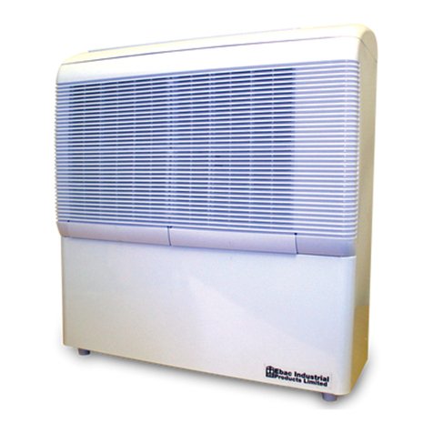
The Heatstar Pegasus is a unit which is intended to be used, in association with other equipment and services,
to facilitate control of the environment within an indoor swimming pool. The term environmental control, in this
instance, relates to humidity level and air temperature.
MAJOR COMPONENTS :
The Pegasus units incorporate the following major components :
- A main supply fan to take air to and from the pool room.
- A refrigeration system to condense moisture from the pool room air.
- Heat recovery coils to transfer energy released by condensing moisture.
MODEL VARIATIONS :
To confirm your exact model, view the data plate which is located by the electrical connections within the
Heatstar unit.
There are two formats of Pegasus units :
The Wall Mounted versions are designed to be located within the pool room. The Through Wall versions are
designed to be located in an adjoining room to the pool room with channels through the adjoining wall taking air
to and from the unit.
Each unit format is available with the following air heating options :
‘Super’Versions :
The term ‘Super’in the model name means that the Heatstar unit incorporates an integral air heating coil to
provide the main pool room air heating. This coil required to be connected to a standard fuel heating boiler via
pipe work.
‘Super Elec’Versions :
The term ‘Super Elec’in the model name means that the Heatstar unit incorporates an electric integral air
heating coil to provide the main pool room air heating. This type of coil does not required to be connected to a
boiler, although will invariably be more expensive to operate.

8
PRINCIPLE OF OPERATION
AIR MOVEMENT :
The Heatstar unit contains a fan which continually draws in air from the pool room and, subsequently, blows the
same air back into the pool room. Therefore, the pool room air is ‘re-circulated’through the Heatstar unit.
HEATING THE POOL ROOM AIR :
The Heatstar ‘Super’model incorporates a heat transfer coil, similar in appearance to a car radiator, which is
plumbed to a separate fuel boiler. The heat generated by the fuel boiler is allowed to be automatically transferred
into the pool room air whenever the falls below the temperature setting.
If this coil is not incorporated within the Heatstar unit, then an independent form of air heating i.e. radiators etc.
would normally be required.
REFRIGERATION CIRCUIT :
The Heatstar unit incorporates a large refrigeration system, similar in principle to a domestic refrigerator. A
refrigeration system of this nature can also be referred to as a ‘heat pump’.
The refrigeration system is connected to a ‘car radiator’like heat transfer coil positioned within the air stream
coming from the pool room.
When the pool room humidity level becomes high with the steam evaporated from the pool water surface, the
refrigeration system switches on automatically and this coil becomes cold.
As the warm humid pool room air is sucked into the Heatstar unit and over this cold coil, the steam within the
pool room air is condensed to cold water as it comes into contact with the cold surface of the refrigerated coil.
Exactly the same principle as condensation forming on a cold glass window. The cold condensed water is then
simply drained away to waste.
HEAT RECOVERY VIA THE REFRIGERATION CIRCUIT :
To evaporate cold water into steam (humidity) you must give the cold water heat. For example, when you boil a
kettle the steam produced contains the heat energy which the kettle has consumed, typically electricity.
However, it is possible to ‘release’the heat which the steam contains - simply by turning the steam back into cold
water again.
This ‘released’heat can be referred to as ‘latent energy’.
Therefore, as the refrigeration system in the Heatstar unit condenses the steam within the pool room air back to
cold water, the heat‘released’from the steam is absorbed into the cold refrigerated coil.
After the ‘released’heat is absorbed into the cold refrigerated coil, it is then ‘pumped’around the refrigeration
system by an electric ‘compressor’motor.
The ‘released’heat can then be returned back into the pool room air as dry heat via a second ‘car radiator’like
heat transfer coil.
The electrical energy used to drive the compressor motor is also all used and transferred in the same manner.
CONTROLS :
The Heatstar unit is able to operate completely automatically and incorporates a control panel for this purpose.

9
INSTALLATION REQUIREMENT SUMMARY
ALL HEATSTAR PEGASUS VERSIONS :
The Pegasus unit would typically require connection to :
An electricity supply.
A waste water drain pipe for condensed water removed from the pool air.
‘SUPER’VERSIONS :
Pipe work connection to standard fuel boiler.
The pipe work should include a motorised heating valve.
All models require to be fixed to a wall using the bracket system provided.
APPLICATION NOTES
If there is no vapour barrier installed in the ceiling of the pool room then problems will be incurred with
condensation within the roof.
If there are no thermal breaks present in aluminium window frames within the pool room then condensation will
occur on the frames.
Any cold bridging within the pool room building will result to condensation.
Any adjoining rooms open to the pool room, such as changing rooms or toilets, should be heated to avoid
condensation forming within these rooms.
Any wood used within the construction of the pool room should be suitably treated in consideration of the
possible variation in humidity levels within the pool room.
The main air re-circulation fan within the Heatstar will run continuously to provide even conditions throughout the
pool room and to enable the humidity and temperature to be constantly sensed.
If the air temperature is not maintained at the correct level, when the pool is uncovered, the evaporation rate will
increase dramatically and condensation may quickly become apparent.
OFF LOADING & MANOEUVRING
The Heatstar unit is heavy and the will require at least two people to safely manoeuvre the unit into position.
Do not drop or jar the unit from any height - not even two or three inches. Move it gently and progressively.
The Heatstar unit can be damaged if due care is not taken, particularly the refrigeration system which may be
fractured resulting in future refrigerant loss.
Do not attempt to lift the Heatstar unit by the pipe out lets - this will cause damage and leaks.

10
LOCATING THE HEATSTAR UNIT
WALL MOUNTED VERSION :
The Heatstar unit would normally be positioned on an appropriate wall within the pool room.
Noise transfer :
The dehumidifier is a comparatively large refrigeration unit and will generate appreciable noise and vibration
when operating. Therefore consideration must be given to vibration transfer through the supporting wall and if
there are any noise sensitive areas which have direct contact to the supporting wall such as bedrooms etc.
Mounting height :
The unit should be mounted so that the bottom is at least 200mm from the floor and the top at least 200mm from
the ceiling. Otherwise, from consideration of effective operation, the unit can be mounted at any height.
However, to offer the best visual impression, the Pegasus should be installed so that the top of the unit is slightly
higher than eye line. This would best ensure that the mechanical fixings etc of the unit are concealed.
Multiple unit installation :
If two or more units are to be used for one application, then the units should be located as far away from each
other as practical to ensure optimum heat distribution.
Maintenance access :
Please consider that the unit will require regular maintenance and servicing.
Therefore the unit should NOT be located :
-at high level, necessitating a ladder to reach the unit.
-On a wall below which there is inadequate pool surround to safely walk across.
Safety :
The installer has to assess the potential risk in the event of the mounting method failing, resulting in the unit
falling from the wall.
Therefore, the unit should NOT be located :
-Immediately above areas which may be occupied, i.e. the pool, spas or sitting areas to minimise the risk
of physical injury.
-Where the unit may fall into the pool or spa water, in consideration that the unit would probably still be
connected to mains electricity to minimise the risk of electrical shock.
Electrical regulations :
The I.E.E. electrical regulations are considered unclear on the issue relating to the use of mains electricity
voltage equipment within the pool room and there are various interpretations.
Heatstar advises that, in order to satisfy the I.E.E. electrical regulations, any dehumidifier should be positioned a
horizontal distance of 2m away from the edge of the pool or spa. The diagonal distance is not relevant.
Heatstar feel that this interpretation, although conservative, is in keeping with the safety orientated intent of the
I.E.E. electrical regulations.

11
THROUGH THE WALL VERSIONS :
The Heatstar ‘Through Wall’model unit would normally be positioned behind an appropriate wall within the pool
room. Typically the Heatstar unit would be located within an adjoining plant room.
Noise transfer :
The dehumidifier is a comparatively large refrigeration unit and will generate appreciable vibration when
operating. Therefore consideration must be given to vibration transfer through the supporting wall and if there are
any noise sensitive areas which have direct contact to the supporting wall such as bedrooms etc.
Mounting height :
The unit should be mounted so that the bottom is at least 200mm from the floor and the top at least 200mm from
the ceiling. Otherwise, from consideration of effective operation, the unit can be mounted at any height.
Multiple unit installation :
If two or more units are to be used for one application, then the units should be located as far away from each
other as practical to ensure optimum heat distribution.
Maintenance access :
Please consider that the unit will require regular maintenance and servicing.
Therefore the unit should NOT be located :
-at high level, necessitating a ladder to reach the unit.
-At a position where access is unreasonably obstructed by other equipment.
Electrical regulations :
As a Through Wall model would be located in a different room to the pool, the stringent electrical regulations
which apply to equipment positioned within the pool room are not applicable.
However, the air grilles are still positioned on the pool room side of the wall and, accordingly, there should be no
conductive bond or connection between the grilles and the actual dehumidifier.
External positioning :
The Heatstar unit is not designed to be mounted externally i.e. outside.
If the unit is located outside, then it must be enclosed in a weatherproof and thermally insulated enclosure, which
must still enable convenient and easy access for regular maintenance.

12
MOUNTING PROCEDURE
WALL MOUNTED MODEL :
In summary :
A bracket is provided which is fixed to the supporting wall.
The chassis only of the unit is then simply lifted onto the bracket. The front facia can then be re-attached to the
chassis.
1) Removing the facia :
Remove the packaging from the unit and carefully manoeuvre the unit to overhang the pallet so the unit will
stand upright.
The front facia is attached to the unit chassis by two screws at the top.
Remove these screws and carefully lift the facia off the unit chassis. The facia simply lifts straight off.
Carefully position the facia where it will not be damaged.
2) Fixing the mounting bracket.
The mounting bracket has holes pre-drilled and should be orientated so that the angled lip is at the top of the
bracket and faces into the room.
The required mounting height of the bracket should be assessed and, using a spirit level, offer up the bracket
and mark the required position of the fixing holes.
The fixings are not supplied with the unit as the type of fixings required will differ in line with the materials used in
the construction of the supporting wall.
The fixings used must be suitable to support the notable weight of the dehumidifier unit.
The head of the fixings used can protrude out from the mounting bracket as there is a corresponding gap in the
back of the unit chassis, i.e. in the case of brick bolts.
3) Mounting the unit chassis.
Once the mounting bracket is firmly secured to the supporting wall, the unit chassis can then be lifted onto the
mounting bracket :
Familiarise yourself with the height and position of the corresponding mounting bar on the back of the unit
chassis.
The front panel of the unit chassis can be unscrewed and removed to enable visual confirmation of the position
of the mounting bar in comparison to the mounting bracket.
The unit chassis can now be lifted onto the mounting bracket.
Caution : Lifting the unit chassis will require at least two people.
Carefully lift and manoeuvre the unit chassis until is mounting bar locates fully over the bracket and the back of
the unit chassis rests against the supporting wall.
Caution : It is very important to confirm that the unit chassis has correctly located onto the mounting bracket and
this should be double checked.
Once the unit chassis is successfully mounted onto the bracket, the front panel can be screwed back in place.

13
4) Re-fixing the front facia.
Once the unit chassis is mounted on the wall, the front facia can then be replaced.
The facia simply slides onto the front of the unit chassis, ensuring that the facia is square onto the unit.
It is advised that replacing the front facia is a job for two people.
Once the facia is in place on the unit chassis, the fixing screws which secure the facia to the unit can be
replaced.
Note : The front facia will require to be removed whilst making the electrical, condensate or heating pipe
connections to the unit.
THROUGH WALL MODELS :
In summary :
Two slot openings are required through the supporting wall into the pool hall.
A flanged frame bracket is provided which is fixed to the supporting wall and which encompasses the slot holes.
The unit is then simply lifted into this frame bracket and fixed in position using the screws provided.
1) Forming the slot holes.
A drawing is enclosed which indicates the size and relative positioning of the slot holes required in the
supporting wall through to the pool hall.
When forming the holes, a spirit level should be used to ensure that the holes are level.
A lintel may be required above the holes as support.
The frame bracket can be used as a guide to check that the holes are correctly sized and aligned.
If the supporting wall is a newly constructed wooden log type construction, then the wall will ‘settle’downwards
over a period of time and extra allowance must be made in the height of the slot openings to allow for this.
If the supporting wall is a cavity wall, then the cavity will required to be sealed from the slot openings. This can
be achieved either by shuttering the slot openings or by sealing the cavity opening around the slots with
expanding foam etc.
2) Removing the frame bracket from the unit chassis.
Remove the packaging from the unit and carefully manoeuvre the unit to lay on its back with the grilles and duct
spigots facing upwards.
Lift of the grilles. The frame bracket is attached to the unit chassis by screws.
Remove these screws and carefully lift the frame bracket off the unit chassis. The frame bracket simply lifts
straight off. The unit chassis can now be stood up on its base.
3) Fixing the frame bracket.
The frame bracket has holes pre-drilled.
Again using a spirit level, offer up the frame bracket over the slot holes through the wall and mark the required
position of the fixing holes.
The fixings are not supplied with the unit as the type of fixings required will differ in line with the materials used in
the construction of the supporting wall.
The fixings used must be suitable to support the notable weight of the dehumidifier unit.
The head of the fixings used can protrude out from the frame bracket i.e. in the case of brick bolts.

14
4) Mounting the unit chassis.
Once the frame bracket is firmly secured to the supporting wall, the unit chassis can then be lifted into the
bracket :
Caution : Lifting the unit chassis will require at least two people.
Carefully lift and manoeuvre the unit chassis until it is fully recessed into the frame bracket.
Whilst the unit chassis is being held in place, the screws which secure the unit chassis to the frame bracket
should be replaced.
5) Sealing the wall slots to the unit chassis.
From the pool room side of the wall ;
Use a silicon based sealant to seal any gap between the outside edge of the duct spigots which protrude into the
wall from the dehumidifier and the wall.
6) Fixing the grilles.
Once the final decoration to the pool hall wall is complete, the air grilles can then be fixed to cover the hole slots
through to the dehumidifier. It is recommend that these grilles be fixed using only a silicon based sealant.
There should be no metal connection between the grilles and the dehumidifier on the other side of the wall.

15
BOILER FIRED HEATING SYSTEM :
(Applicable to ‘Super’Versions only) :
ABOUT THE HEATING CIRCUIT :
A separate fuel boiler is used to provide a source of heat.
The Heatstar unit simply transfers the heat provided by the fuel boiler into the pool room air.
The heat produced by the fuel boiler is taken to the Heatstar unit using a closed circuit of pipe work filled with
water, similar in principle to a standard central heating system.
The fuel boiler heats up the water within the closed pipe circuit, which the boiler circulating pump then pumps
through the pipe work to the Heatstar unit.
The Heatstar unit transfers this heat from the closed pipe circuit, prior to the water being recirculated back to the
fuel boiler for the heating process to continue.
This type of circuit is known as an LTHW system (Low Temperature Hot Water).
FUEL BOILER TYPE :
The boiler required is a normal domestic / commercial type, identical to that which would often be used to
provide heat to standard radiators.
A specialised ‘swimming pool’boiler cannot be used as these can only be used to heat the pool water and not
the pool room air.
High efficiency condensing boilers can be used.
Open vented or pressurised system boilers can be used as long as the pressure is not allowed to exceed 25
P.S.I.
A balanced flue arrangement is preferable and necessary if the pool room air can enter the plant room.
Two smaller boilers can be used, in place of a single large boiler, if this offers any plant room space benefits.
BOILER SIZE :
The amount of heat which a boiler is capable of producing is described as the ‘boiler out put capacity’. This
should not be confused with the boiler input rating which is not the same.
This will normally be rated in BTU’s (British Thermal Units). For reference 3412.14 BTU’s is equal to 1 kW .
The fuel boiler must be able to provide the heat out put stipulated within the original heat load calculations,
previously provided. Contact Heatstar if there is any doubt as to the correct out put rating.
BOILER WATER CIRCULATING PUMP :
The LTHW circulating pump must be able to deliver the required flow rate at the indicated resistance.
If the LTHW flow temperature differential across the Heatstar unit is greater than 11°C / 20°F, then the flow rate
is inadequate.
The boiler water circulating pump should be wired to run continuously.

16
LTHW SPECIFICATIONS :
The enclosed LTHW specification table indicates the required flow temperatures, rates and resistance. If the
LTHW supply provided to the Heatstar unit falls short of these requirements, then the full heating capacity will
not be achieved.
BOILER PIPE CONNECTIONS TO HEATSTAR UNIT :
The pipe connections, which are labelled, should be made with compression fittings. Soldered connections
should not be used.
The connections should be made via breakable couplings.
DRAIN DOWN VALVES :
Drain down valves should be provided at appropriate points around the boiler pipe work circuit.
ROUTING OF PIPE WORK :
Do not route pipe work across the service access panels of the unit.
MOTORISED HEATING VALVES :
The motorised heating valves are simple electric valves which, when powered open, allow the flow of hot water
from the boiler into the heat exchange coils to provide heating. Such valves are commonly used within domestic
central heating systems.
An external motorised heating valve will need to be provide.
The external motorised heating valve is powered electrically from the electrical connections within the Heatstar
unit.
The system is compatible for use with either two port or three port motorised valves.
The valve can either be ‘spring close’or ‘power close’in type.
The heating valve should open and allow LTHW to the air heating coil when power is available.
The electrical supply to the valve from the Heatstar unit is a switched 240v supply which is either on or off and
not proportional.
INSULATION OF PIPE WORK :
All LTHW pipe work should be thermally insulated to limit heat loss.
AIR VENTING OF THE LTHW PIPE WORK :
An air vent should be positioned at the top pipe outlet of the air heating coil within the Heatstar unit. An air vent
should also be positioned at the highest point in the LTHW pipe circuit.
ISOLATION VALVES :
A method of isolating the flow of LTHW through the Heatstar unit should be included within both the flow and
return pipe connection. This will enable maintenance to be carried out on the LTHW pipe circuit within the
Heatstar unit without the need to drain down the pipe circuit.
BOILER MANUFACTURERS DATA :
Always refer to the boiler and boiler circulating pump manufacturers installation information prior to designing the
heating circuit.

17
ELECTRICAL INSTALLATION
WARNING
The Heatstar unit embodies electrical and rotational equipment.
Only qualified personnel who thoroughly understand the operation of this equipment and any associated
machinery should install, start-up or attempt maintenance of this equipment. Non-compliance with this warning
may result in personal injury and / or equipment damage.
Never work on any control equipment without first isolating all power supplies from the equipment.
Never connect this equipment to a 13 Amp plug and socket.
Never connect this equipment to any outlet within the actual swimming pool.
STANDARDS AND REGULATIONS
All relevant national standards and local electricity board regulations must be observed at installation.
ELECTRICAL CONNECTIONS
Wall mounted models :
Remove front facia.
Unscrew top right panel marked with electrical warning label.
This panel pivots forward to reveal the electrical connection terminals.
Through Wall models :
Unscrew top left panel marked with electrical warning label.
This panel pivots forward to reveal the electrical connection terminals.

18
ELECTRICAL CONNECTIONS REQUIRED
ALL MODELS :
MAINS power electricity supply TO Heatstar unit.
HEATSTAR ‘SUPER’VERSIONS ONLY :
Connection FROM Heatstar unit TO external air heating valve.
ELECTRICAL CIRCUIT PROTECTION
EARTHING :
The Heatstar unit must be connected to an appropriate safety earth. Failure to do so presents an electrical shock
hazard.
The circuit protection to the Heatstar unit should allow for three separate aspects being a Residual Current
Device, Miniature Circuit Breaker and local Isolator Switch :
RCD :
The mains power electricity supply to the Heatstar unit should be routed via a suitably sized Residual Current
Device (RCD).
An RCD is sometimes referred to as a Residual Current Circuit Breaker (RCCB) or Earth Leakage Circuit
Breaker (ELCB).
An RCD rating of 30mA is normally advised.
The purpose of the RCD is to protect against fatal electric shock to personnel, by reducing to safe levels (not
eliminating) the value and length of time a person is exposed to current flow through the body.
Equally the RCD will help protect plant and equipment from fires started by low fault currents passing from Live
to Earth, that a normal fuse or circuit breaker may not detect.
CIRCUIT BREAKER :
In addition to an RCD, the mains supply to the Heatstar unit must be protected by a Miniature Circuit Breaker
(MCB).
An MCB is a circuit protection device similar to a simple fuse, but re-settable.
An MCB normally have two modes of operation :
Thermal Overload Protection - to protect cabling and equipment from ‘long term’over current damage.
Magnetic Short Circuit Protection - to protect cabling and equipment against very high fault currents caused by
terminal component failure.
An MCB is rated by the normal carrying current, normal carrying voltage and by the maximum fault current and
voltage they can safely / repeatedly break.
As the Heatstar unit incorporates large electric motors, with high initial starting current loads, we recommend the
use of a ‘Type C’MCB, which allows for this initial starting load.
Standard fuses should not be used in place of a proper MCB.

19
LOCAL ISOLATOR SWITCH :
A separate Isolator Switch must be positioned immediately adjacent to the Heatstar unit to isolate all electrical
supply.
The isolator switch must be within clear view from the Heatstar unit and not more than 3 metres away in
distance.
When in the ’off’position, the isolator used must provide a gap of at least 3mm between the internal electrical
contacts.
There is no ‘On / Off Switch’on the Heatstar unit.
ROUTING CABLES INTO THE HEATSTAR UNIT :
A hole is provided through which the electrical cable can enter the unit.
If this is not convenient, drill an appropriate hole at a convenient location in the unit case to route the cable to the
electrical terminal connections. The cables should be encased in conduit where routed through the unit. Take
care not to damage any internal component or position the cable where it can be drawn into the fans. With the
wall mounted format unit, only the rear of the unit chassis will not be covered by the facia.
MAINS ELECTRICITY SUPPLY
MAXIMUM SUPPLY LOADS :
The table in electrical specifications indicates the maximum loadings for each model.
The Heatstar unit incorporates two motors types being the main supply fan and, largest of all, the refrigeration
compressor motor.
The starting of the motors are off set using time delays to limit the starting electrical load.
The initial load drawn, for a fraction of a second, by each of the motors on starting, will be approximately three
times the normal running Amps.
The normal running amps drawn by the Heatstar unit will vary depending on the pool room temperature/humidity
conditions. This is due to internal working pressures within the system and is quite normal.
SUPPLY VOLTAGE :
The voltage limits indicated in the Electrical Specifications must not be exceeded.
The correct voltage must be available under the Starting Load Current.
POWER CABLE SIZING :
The Heatstar unit must be connected with the correct cable size.
The cable supplying electricity to a machine with a given electrical load must increase in cross sectional area as
the length increases in order that the voltage drop within the cable does not exceed the recommended limits.
Power cables must have a minimum rating of 1.1 x Full Load Current.
The mains cable should be run in Conduit or armoured casing.
Table of contents
