Heatwagon VF400 Manual
Installation and Maintenance Manual
Please retain this manual for future reference.
342 N. Co. Rd. 400 East
Valparaiso, IN 46383
888-432-8924 • Fax 219-462-7985
www.heatwagon.com
Revision 12-16
CAUTION: Do not use this heater in a
space where gasoline or other liquids
having lammable vapors are stored.
Construction
Heater
VF400
C US
Dept. of Buildings
29-05-E

I PORTANT INFOR ATION! READ FIRST
The heater is designed for use as a construction heater under CSA-B140.8-1967 (General
Requirements For Oil Burning Equipment) and UL-733 (Oil Fired Heaters and Direct Fired
Heaters). Heater is not intended for use in pest remediation. The primary purpose of construc-
tion heaters is to provide temporary heating of buildings under construction, alteration, or repair
and to provide emergency heat. Properly used, the heater provides safe, economical heating.
Products of combustion are vented outside the area being heated.
Use of the heater must be in accordance with this Standard and in compliance with all governing
state and local codes.
We cannot anticipate every use which may be made for our heaters. CHECK WITH YOUR
LOCAL FIRE SAFETY AUTHORITY IF YOU HAVE QUESTIONS ABOUT LOCAL REGULATIONS.
Other standards govern the use of fuel gases and heat producing products in specific applica-
tions. Your local authority can advise you about these.
FOR YOUR SAFETY
DO NOT USE THIS HEATER IN A SPACE WHERE GASOLINE OR OTHER LIQ-
UIDS HAVING FLA ABLE VAPORS ARE STORED OR USED.
CONSTRUCTION HEATER GENERAL HAZARD WARNING:
Failure to comply with the precautions and instructions provided with this heater, can
result in death, serious bodily injury and property loss or damage from hazards of
fire, explosion, burn, asphyxiation, carbon monoxide poisoning, and/or electrical
shock.
Only persons who can understand and follow the instructions should use or service
this heater.
If you need assistance or heater information such as an instruction manual, labels,
etc., contact your local Heat Wagon dealer or the manufacturer.
W A R N I N G
Fire, burn, inhalation, and explosion hazard. Keep solid combustibles, such as build-
ing materials, paper or cardboard, a safe distance away from the heater as recom-
mended by the instructions. Never use the heater in spaces which do or may contain
volatile or airborne combustibles, or products such as gasoline, solvents, paint thin-
ner, dust particles or unknown chemicals.
Not for home or recreational vehicle use!
If you have read this entire manual and you still have ques-
tions, please call us at 219-464-8818

Table of Contents:
Page
Safety & Caution . . . . . . . . . . . . . . . . . . . . . . . . . . . . . . . . . . . . . . . . . . . .4
Specifications . . . . . . . . . . . . . . . . . . . . . . . . . . . . . . . . . . . . . . . . . . . . . . .4
Operating nstructions . . . . . . . . . . . . . . . . . . . . . . . . . . . . . . . . . . . . . . . .5
Maintenance . . . . . . . . . . . . . . . . . . . . . . . . . . . . . . . . . . . . . . . . . . . . . . . .7
Troubleshooting . . . . . . . . . . . . . . . . . . . . . . . . . . . . . . . . . . . . . . . . . . . . .8
llustrated Parts Breakdown . . . . . . . . . . . . . . . . . . . . . . . . . . . . . . . . . . .12
Wiring Diagrams . . . . . . . . . . . . . . . . . . . . . . . . . . . . . . . . . . . . . . . . . . .15
Exhaust Flue Pipe Guidelines . . . . . . . . . . . . . . . . . . . . . . . . . . . . . . . . .18
Installation and Maintenance Manual
Model VF400
Construction Heater
342 N. Co. Rd. 400 East • Val araiso, IN 46383
219-464-8818 • 888-432-8924 • Fax 800-255-7985
www.heatwagon.com
WARRANTY
All new Heat Wagon and Sure Flame heaters and fans are guaranteed against defective materials and workman-
ship for one (1) year from Heat Wagon invoice date.
Warranty repairs may be made only by an authorized, trained and certified Heat Wagon dealer. Warranty repairs
by other entities will not be considered. Warranty claims must include model number and serial number.
Components are guaranteed to the extent of the components manufacturer’s warranty.
LI ITATIONS
Warranty claims for service parts (wear parts) such as spark plugs, igniters, filters, nozzles, and flame rods will not
be allowed. Diagnostic parts such as voltage meters and pressure gauges are not warrantable. Evidence of improp-
er fuel usage, fuel pressures outside of manufacturer’s specification, poor fuel quality, and improper electric power,
misapplication or evidence of abuse may be cause for rejection of warranty claims.
Labor, travel time, mileage and shipping charges will not be allowed. Minor adjustments of heaters are dealers’
responsibility. Defective parts must be tagged and held for possible return to the factory for 60 days from date of
repair. The factory will provide a return goods authorization, (RGA) for defective parts to be returned. No war-
ranty will be allowed for parts not purchased from Heat Wagon.

SAFETY & CAUTION
• nstructions given in this manual and the applicable regulation of the local authorities
must be followed.
• The unit may be operated only by those persons who have been instructed in it’s use.
• The unit is to be installed and operated in such a way as to ensure safety of employees and
surroundings.
• Never cover the unit’s air openings.
• Always secure an adequate fresh air supply to the unit.
• Never stand in front of the discharge end of the heater.
• Do not introduce foreign objects into the unit.
• Do not expose the unit to direct water jets.
• All electric cables outside the unit are to be protected against damage.
• Always disconnect the unit from power supply when maintenance or service is being
performed.
• IF NOT OPERATED WITHIN GUIDELINES OF THESE OPERATING INSTRUCTIONS
ANUFACTURER WILL NOT BE HELD RESPONSIBLE AND WARRANTY
WILL BECO E VOID.
4
SPECIFICATIONS
odel No. VF400
Fuels: #1 or #2 Kerosene, Diesel, Heating Fuel
Capacity: 400,000 BTU/HR
Blower: 2,100 CFM 1/2” SP
Electrical Rating: 120 Volts, 10 Amps
Fuel Consumption: 3 GPH Max
Remote Thermostat: On/Off
Max. Discharge Temp.: 200ºF @ 0ºF Ambient
Duct Size: 12” Dia., 50 ft. max (straight), temp rating 300ºF min.
Weight (approximate): 400 lbs.
Fuel Supply: anifold Pressure (Fuel Pump) Burner Nozzle
110 psi 3 GPH x 80A

OPERATING INSTRUCTIONS
INSTALLATION
• When transporting, use both lifting eyes located on sides of heater.
• Place the unit on a level and non-combustible surface.
• Minimum clearances from combustible materials for indoor or outdoor installation on
combustible flooring:
- outlet, minimum 10 feet
- sides, minimum 3 feet
- top, minimum 3 feet
- flue pipe exhaust, gas discharge minimum 2 feet
• Manufacturer recommends a free zone of 5 feet around the unit and a minimum distance of 10
feet at the unit’s flue gas openings are to be maintained.
• f the unit is placed indoors, secure an adequate fresh air opening for the burner combustion air.
• The unit may not be installed and operated in premises where explosive or combustible fumes
or dust are present. Check the regulation of local authorities, when necessary.
• Make sure that neither the air inlet nor the air outlet is obstructed.
FUEL SUPPLY
• This heater will burn kerosene (#1 or #2), diesel fuel (#1 or #2), and heating fuel (#1 or #2). t is
highly recommended to use winterized fuel with ambient temperatures less than 20ºF and to
also install optional circulation or fuel tank heaters.
• The installation of this heater must comply with all applicable local codes.
• Check and clean fuel filter (if necessary) on a weekly schedule.
ELECTRICAL
• Electric cable extensions must be connected based on the unit capacity and cable length.
• Connect unit to a power supply with a suitable appliance receptacle (15 Amp).
• Confirm voltage at heater connection (105V min.) to ensure proper operation.
EXHAUST FLUE PIPE
• The unit is to be connected to a flue pipe with adequate draft, to ensure the proper start and
operation of the unit. Refer to page 16.
• The flue pipe is to be made of non-combustible material and clearances from combustible
materials must be a minimum 8 inches (temperature of flue gases is approximately 410º F).
• The flue pipe and its installation must comply with the regulations and instructions given by
the local authorities.
5

START UP
• Only people who are trained in the operation and supervision of this heater should operate
and maintain the unit.
• Check the unit to make sure that there are no visible defects on the control and safety devices
and that the unit has been installed correctly.
1. Check that the control switch on the control box is in position “0” (STOP).
2. Pre-select desired room temperature on the room thermostat. The temperature must be set
higher than the ambient temperature.
3. Turn the control switch in control box to position “1” (HEAT NG).
4. When the ambient temperature level is low, the burner switches on automatically. The fan
does not switch on until the set temperature (104ºF) of the heat-exchanger has been
reached (will take approximately 1-5 minutes).
• After starting, the unit runs fully automatically with the pre-selected room temperature
thermostat and it is controlled by its own control devices and safety limit controls.
• The room thermostat (TSTAT) and burner sensor control the running sequences of the
burner and the fan sensor controls the fan function.
• Overheat limit reset (STB) controls and shuts off the heater (burner) in the case of overheating.
• The unit can also be used for ventilation purposes only, if needed.
1. Turn the control switch on the control box to position “2” (VENT LAT ON).
2. The unit is now in the continuous ventilating mode.
3. Heating is not possible in this mode.
DUCTING (Warm Air)
• Clearness from combustible materials have to be a minimum of 4 inches.
• Use steel ducting or fabric ducting capable of withstanding a minimum temperature of 300ºF.
• Maximum length of duct: 50’ (straight).
• Duct diameter: 12”.
• Make sure that the duct is safely and properly fastened to the outlet.
• Avoid sharp bends and corners to ensure maximum air flow and avoid back pressure/heat
accumulation in heater.
• FA LURE TO COMPLY W TH THESE RECOMMENDAT ONS COULD RESULT N SHUTDOWN
OF THE HEATER.
SHUT DOWN
• Turn control switch to position “0” (STOP).
WARNING!
UNIT AY BE UNPLUGGED IN E ERGENCY SITUATIONS ONLY. OTHERWISE, DO NOT
STOP THE UNIT BY UNPLUGGING IT. UNIT NEEDS TO COOL DOWN USING ITS OWN
FAN. FAILURE TO CO PLY WITH PROPER SHUT-DOWN PROCEDURES CAN CAUSE
DA AGE TO THE CO BUSTION CHA BER, HEAT EXCHANGER, SAFETY FEATURES AND
ALSO VOID WARRANTY.
6
mportant!
The air supply fan continues running
to cool down the combustion
chamber/heat exchanger and then
stops later. The fan can restart for
several times before finally switching off!

AINTENANCE
Prior to starting any maintenance work, wait until unit cools down fully and fan shuts off
before unplugging unit and beginning any maintenance work.
(Shut Down Procedures page 6)
To ensure the proper function of the unit, it must be serviced on regular basis. Maintenance can
be performed, (excluding the control devices and safety limit controls), by an authorized trained &
certified Heat Wagon dealer. The control devices and safety limit controls do not need routine
maintenance. f these items fail they must be replaced.
- Do not use any aggressive cleaning agents (which are harmful or environmentally
unfriendly), when cleaning the unit.
- Do not use water jet when cleaning the unit.
- Pressurized air may be used for maintenance. Be careful not to damage the fan blower wheel
with too much pressure.
- Check whether the unit is free from mechanical damage. Replace faulty parts as necessary.
- Check fan blower wheel at regular intervals and clean it when needed.
- Check functionality of control and safety devices regularly.
- Have the flue gas values of the burner checked regularly by authorized agents.
- Be sure to store the unit in a dust free and dry place when it is not used for a long period of
time. Cover the exhaust flue to prevent entry of foreign objects.
SERVICE
• The complete unit, including heat exchanger, combustion chamber and burner should be
cleaned from dust and dirt after every heating period, at a minimum of once per year.
-Removal of combustion chamber/heat exchanger:
For proper cleaning of the unit, manufacturer recommends removal of the complete
combustion chamber with heat exchanger. Clean combustion chamber and heat exchanger tube
with a brush. Vacuum all loose ash and soot. Close all cleaning flanges carefully to avoid damage
to gasket material.
-Disassembling of burner:
1. Disassemble four tightening bolts on the combustion chamber flange and remove burner’s
mounting flange. Take care not to damage the flange seal.
2. Pull out the burner. Take care not to damage the burner head and power cable. Clean blower
wheel, ignitor electrodes, and photocell. Replace fuel nozzle and fuel filter.
Refer to seperate burner manual for adjustment of burner.
7

1. Turn the
heater to
position #1
and nothing
happens.
2. The heater
runs for a little
while, but
shuts down. It
won’t come on
again until the
limit switch is
reset.
• ower supply cord
• Burner reset button on the burner flame
safeguard control box is tripped
• Overheat limit switch is tripped
• Burner sensor
• Heater control unit (HCU)
• Burner nozzle is improperly sized
• Incorrect burner fuel pump pressure
• Restricted airflow
• Overheat limit switch
• Test for 120 volts between L1 and L2 on the main terminal block.
• Reset the button on the flame safeguard control.
• Reset the switch, which is on the side of the heater near the warm air outlet.
• On the heater control unit (HCU) disconnect the wires from terminals X10 and
X11. Using an ohm meter, check the resistance between the two wires using
the 1K ohms chart on page 16.
• On the main terminal block, check for 120 volts between terminals 8 and N when
the 3-position switch is in the HEAT position.
• Nozzle is 3 G H x 80º A.
• Use a high pressure gauge (160 SI) with a 1/8” N T inlet. Install gauge in the
pressure tap port located on the top of the fuel pump. Run the unit and adjust
the manifold pressure by turning the pressure adjusting screw (on the right hand
side of the fuel pump) in or out until the gauge reads 110 SI.
• Check for dirt or ice buildup on the air inlet or blower wheel. If using duct on the
air outlet, insure the back pressure does not exceed a static pressure of .5” W.C.
• Adhere to the proper shut down procedures. ower must remain at the unit until
it cools down fully. Blower will shut down on its own when cool. Test overheat
limit switch for continuity between the two male terminals at room temperature.
Replace if overheat limit switch fails test.
VF400 TROUBLESHOOTING
Symptom Possible Causes Possible Solutions
8

9
3. I get the
burner motor
to come on,
but the heater
won’t ignite.
4. The heater
has a loud
rumbling
sound.
• Fuel pressure or volume
• Air inlet damper adjustment
• Ignition electrodes
• Electronic igniter
• Solenoid valve
• Air damper setting
• Dirt on burner blower wheel
• Flue pipe setup or flue pipe
restrictions
• Fuel pump pressure
• Fuel nozzle size
• Restricted heat exchanger
• Use a high pressure gauge (160 SI) with 1/8” N T inlet. Install gauge in the
gauge port located on top of the fuel pump. Run the heater. Adjust the
pressure by turning the pressure adjusting screw (located on the right hand side
of the fuel pump) counter clockwise until the gauge reads 110 SI.
• Rough setting at 6.75 open. Minor adjustments from the rough settings can be
made to achieve a smooth sounding burner with no soot from the flue pipe.
• Clean with fine sandpaper. Make sure it is free from buildup or cracks.
• Disconnect fuel solenoid valves and turn on the burner. ull the igniter (using
insulated pliers) away from the electrodes slowly. A rainbow colored arc should
travel between the igniter and electrode bus bars at a distance of 3/8 of an inch
for a duration of 4-5 seconds.
• If there is power at the flame safeguard control and no power out to the
solenoid valves, replace the flame safeguard control. Check for continuity
between the wires on the solenoid valve coil.
• Rough setting at 6.75 open on scale. Minor adjustments from the rough
settings can be made to achieve a smooth sounding burner with no soot from
the flue pipe.
• Clean the burner blower wheel with a small brush.
• Refer to the flue pipe chart in this manual. Check flue for restriction.
• Use a high pressure gauge (0-160 SI) with 1/8” N T inlet. Install gauge in the
gauge port located on top of the fuel pump. Run the heater. Adjust the
pressure by turning the pressure adjusting screw (located on the right hand side
of the fuel pump) counter clockwise until the gauge reads 110 SI .
• Nozzle is 3 G H x 80º A.
• Refer to the cleaning instructions in this manual.
VF400 TROUBLESHOOTING
Symptom Possible Causes Possible Solutions

10
5. The heater
blows black
smoke out of
the vent stack.
6. The burner
seems to
cycle on and
off more than
what it should.
• Air damper setting
• Dirt on burner blower wheel
• Flue pipe setup or flue pipe
restrictions
• Fuel pump pressure
• Restricted fuel filter
• Incorrect fuel nozzle size
• Restricted heat exchanger
• Fuel pump pressure
• Restricted fuel filter
• Dirt on main air blower or improper setup
of outlet air duct
• Burner sensor
• Heater Control Unit (HCU)
• Rough setting at 6.75 open on scale. Minor adjustments from the rough
settings can be made to achieve a smooth sounding burner with no soot from
the flue pipe.
• Clean the burner blower wheel with a small brush.
• Refer to the flue pipe chart in this manual. Check flue for restriction.
• Use a high pressure gauge (0-160 SI) with 1/8” N T inlet. Install gauge in the
gauge port located on top of the fuel pump. Run the heater. Adjust the
pressure by turning the pressure adjusting screw (located on the right hand side
of the fuel pump) counter clockwise until the gauge reads 110 SI.
• Clean or replace fuel filter.
• Nozzle is 3 G H x 80º A.
• Refer to the cleaning instructions in this manual.
• Use a high pressure gauge (0-160 SI) with 1/8” N T inlet. Install gauge in the
gauge port located on top of the fuel pump. Run the heater. Adjust the
pressure by turning the pressure adjusting screw (located on the right hand side
of the fuel pump) counter clockwise until the gauge reads 110 SI.
• Clean or replace fuel filter.
• Check for dirt or ice buildup on the air inlet or blower wheel. If using duct on
the air outlet, insure the back pressure does not exceed a static pressure of
.5” WC.
• On the heater control unit (HCU) disconnect the wires from terminals X10 and
X11. Using an ohm meter, check the resistance between the two wires using
the 1K ohms chart on page 16.
• If all of the above check good, replace the HCU.
VF400 TROUBLESHOOTING
Symptom Possible Causes Possible Solutions

11
7. The burner
starts, but the
main fan
never comes
on.
8. The burner
continues to
run, but the
fan cycles on
and off.
• Fan sensor
• Heater Control Unit (HCU)
• Blower motor relay
• Blower motor
• Fuel pump pressure
• Fan sensor
• Heater Control Unit (HCU)
• On the heater control unit (HCU) disconnect the wires from terminals X12 and
X13. Using an ohm meter, check the resistance between the two wires using
the 1K ohms chart on page 16.
• Turn the 3-position main switch to the fan position. If the blower runs, check the
fan sensor. If it is good, replace the HCU.
• Turn the 3-position main switch to the fan position. If the relay pulls in, check
for voltage between the L1 and L2 terminals. Then check the voltage between
terminals T1 and T2. The voltage should be the same. If it is much lower,
replace the relay.
• Turn the 3-position main switch to the fan position. Check for voltage between
terminals T1 and T2 on the motor relay. If the voltage is good, replace the
motor.
• Use a high pressure gauge (0-160 SI) with 1/8” N T inlet. Install gauge in the
pressure tap port located on top of the fuel pump. Run the heater. Adjust the
pressure by turning the pressure adjusting screw (located on the right hand side
of the fuel pump) until the gauge reads 110 SI.
• On the heater control unit (HCU), disconnect the wires from terminals X12 and
X13. Using an ohm meter, check the resistance between the two wires using
the 1K ohms chart on page 16.
• Turn the 3-position main switch to the fan position. If the blower runs, check the
fan sensor. If it is good, replace the HCU.
VF400 TROUBLESHOOTING
Symptom Possible Causes Possible Solutions

12
Heat Wagon VF400 Parts List
ITE PART# DESCRIPTION
1 HWP 2109001 HEATER FRAME
2 HWP 2109002 COVER PLATE
3 HWP 2109003 S DE PANELS (2)
4 HWP 2109004 REAR HANDLE
5 HWP 2109005 BOTTOM PLATE
6 HWP 2109006 FLUE COLLAR
7 HWP HW1065 WHEEL (2)
8 HWP 2109008 WHEEL SHAFT
9 HWP 2109009 BURNER CHAMBER ASSEMBLY
10 HWP 2109010 FAN GUARD, LEFT
11 HWP 2109011 FAN GUARD, R GHT
12 HWP 12440 FAN, COMPLETE
13 HWP 40900 NLA
14 HWP 2109014 FORKL FT EYE
15 HWP 120008 BURNER VF400
16 HWP 2109016 BURNER COVER
17 HWP 211153 O L PREHEAT CO L
18 HWP 120009 O L F LTER-COMPLETE
19 HWP 120004 O L WAND
20 HWP 120005 O L WAND HOLDER
21 HWP 120020 O L HOSE (2 PCS.)
22 HWP 41000 MA N CONTROL BOX
23 HWP 2109023 BRACKET, MA N CONTROL BOX
24 HWP 120021 MA N SW TCH
25 HWP 21800 OVERHEAT L M T SW TCH
25A HWP 21800 OVERHEAT L M T SW TCH(bimetallic)
25B HWP 21400** OVERHEAT L M T (CAP LLARY)
ITE PART# DESCRIPTION
26 HWP 40850 THERMOSTAT BOX
27 HWP 20579 HEATER CONTROL UN T
28A HWP 20581 FAN SENSOR (FOR POS. #27), 4” TUBE
28B HWP 20583 FAN SENSOR, 9” TUBE
29 HWP 20582 BURNER SENSOR (POS. #27)
30 HWP HC1020 POWER CORD & PLUG
NOT SHOWN N D AGRAM
SFP 2436 CONTACTOR
HWP 46950 CAPAC TOR
HWP 80200 POWER CORD & PLUG (2 PCS.)
HWP 2109031 RAD AT ON SH ELD (UPPER)
HWP 12000 SMOKE FLUE W/RA N CAP
SFP 2453 REMOTE THERMOSTAT
HWP 100428 BURNER GASKET
HWP 21724011 FLANGE ADJ. FOR 12008
HWP 40850SS S L CONE SEAL - 40850 THERM. BOX
HWP 210047 RUBBER EDGE SEAL (SOLD PER FOOT)
(30 FEET PER HEATER)
HWP 180036 K T TO CHANGE OVERHEAT L M T
HWP 65900 RESTRA NT FOR SENSORS
HWP 12009B ELEMENT W/RUBBER GASKET
HWP HV1060 0-300 PS L QU D F LLED GAUGE
HWP F102GG1 BLOWER MOTOR SUPPORT
HWP SP12440 MOTOR FOR 12440 FAN ASSY.
HWP 180036 H GH L M T CHANGEOVER K T
SFP 2436 CONTACTOR, MOTOR START NG RELAY
ACC WD1225 OPT ONAL DUCT 12”x25’
18
Also see Control Box Parts page 16.
**Note: Overheat limit switch - New design (capillary tube)
S/N M2728-2746, M4769 and greater
25A
25B
28A
28B
25B (Reset)

13
WAYNE BURNER
PARTS BREAKDOWN
pg. 14
HW 100926013
Gun Assembly
See Gun View
HW 20627
120V Motor
HW 21642
Blower Wheel
HW 100386
Coupling
HW 100386
Coupling
31946-003
Tube/Flange
HW 100531-001
Air Cone
HW 13495
Fuel ump
HW 63266013
Static Baffle 30º
12” Setting
HW 13666
Cad Cell
Fan Setting G2038
EX LODED VIEW
EX LODED VIEW
HW 21659
Ignition Transformer
HW 13077
rimary Control
15 Sec.
Flame Safeguard
Control
HW 14409
Kip Oil Valve
ASSEMBLED VIEW
14
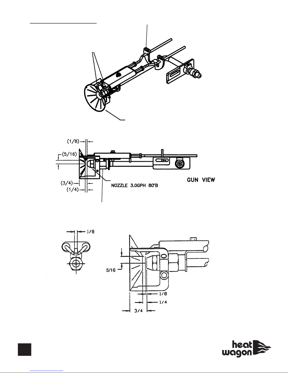
ELECTRODE SETTING
HW 21684 - Electrodes, 2 iece Set
HW 100989061 - 1 iece Electrode
HW 13276 - Buss Bar Support
HW 100393-001
Flamelock Assembly
HW 32101
HW 12362 - Nozzle Adapter
15
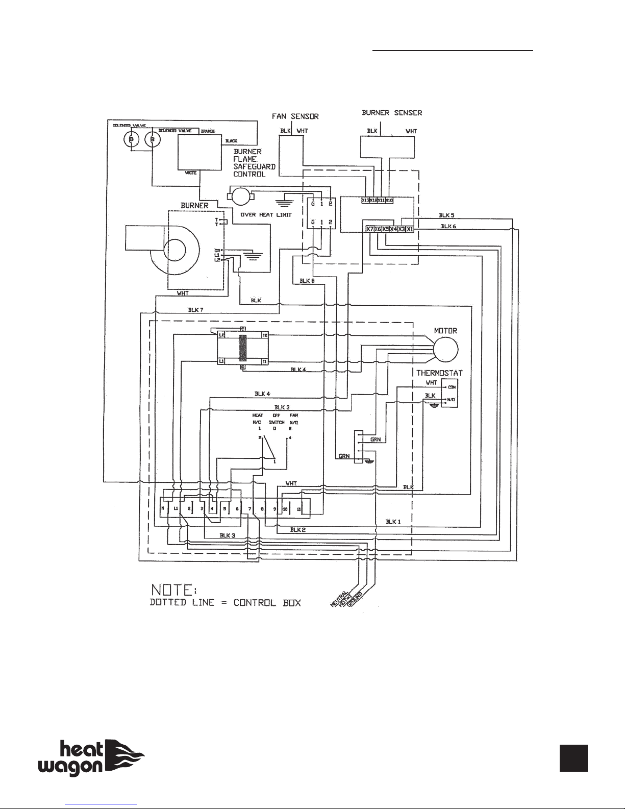
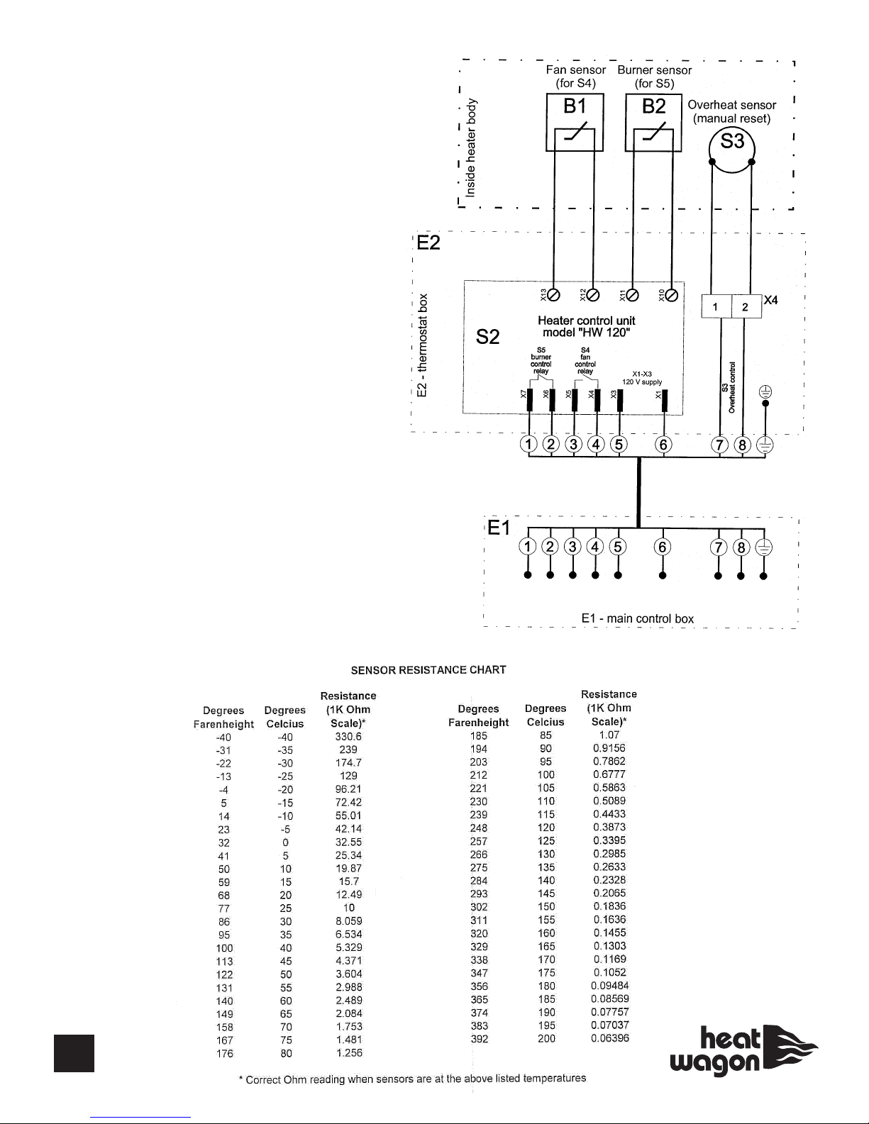
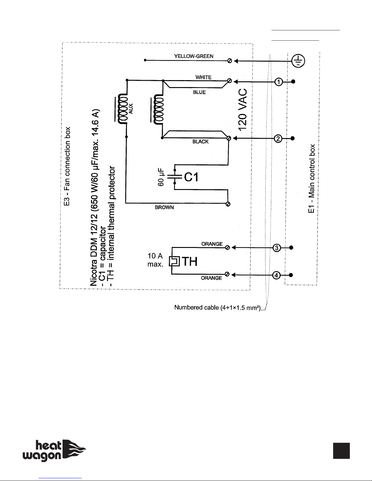
120 Volt 1 PH CONTROL BOX WIRING
120 Volt 1 PH
ITE PART# DESCRIPTION
E1 HWP 41000 MA N CONTROL BOX
E2 HWP 40850 THERMOSTAT BOX
E3 HWP 40900 FAN CONNECT ON BOX
S1 HWP 26400 MA N SW TCH
S2 HWP 20579 HEATER CONTROL UN T,
MODEL HW120
B1 HWP 20581 FAN SENSOR (for S4)
HWP 20583
B2 HWP 20582 BURNER SENSOR (for S5)
S3 HWP 21800 OVERHEAT L M T SW TCH (B METALL C)
HWP 21400 OVERHEAT L M T (CAP LLARY)
X1 HWP 36701 TERM NAL BLOCK (E1)
X2 HWP 36100 GROUND NG BLOCK (E1)
HWP HC1020 POWER CABLE & PLUG
X4 HWP 36701 TERM NAL BLOCK (E2)
X5 HWP 36701 TERM NAL BLOCK (E3)
16
120 Volt 1 PH
MAIN
RED
BLOWER OTOR
SCHE ATIC
17

18
EXHAUST FLUE PIPE GUIDELINES
CAPACITY OF TYPE B DOUBLE-WALL
VENTS SERVING A SINGLE DRAFT
HOOD-HEATER x 1000 BTU'S
FOR INDOOR APPLICATIONS
8101214
TOTAL
VENT
HEIGHT((HH))F
EET
LATERAL
LENGTH
((LL))FEET
60370 570 850 1170
2285 455 650 890
6273 435 630 870
12 255 406 610 840
80415 660 970 1320
2322 515 745 1020
8303 490 720 1000
16 281 458 685 950
10 0 450 720 1060 1450
2355 560 850 1130
10 330 525 795 1080
20 300 486 735 1030
15 0 525 840 1240 1720
2414 675 985 1350
15 373 610 905 1250
30 328 553 845 1180
20 0 575 930 1350 1900
2470 755 1100 1520
10 443 710 1045 1460
20 410 665 990 1390
30 380 626 945 1270
30 0 650 1060 1550 2170
2535 865 1310 1800
20 473 784 1185 1650
40 415 705 1075 1520
VENT DIAMETER (D) INCHES
F
19
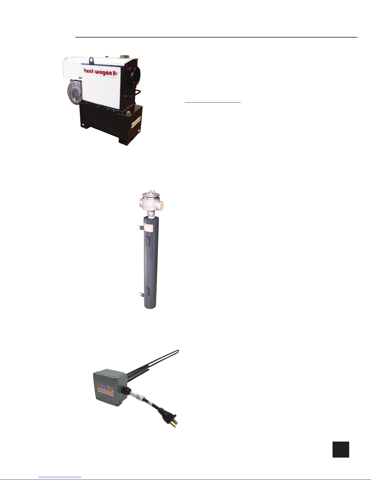
Oil Fired
Fuel Tank
VF400 Tank (FT400)
• 75 gallon tank
• Single wall tank
• Forkli t capability rom all our sides
• Minimum 25 hour run time
• 160 lbs. (empty) - 750 lbs. ( ull)
Immersion Heater for
Fuel Tank (FT400HT)
• 120V (1000 watts)
• Keeps uel at optimal low
rate and prevents uel “gelling”
• Must be used in conjunction
with the FT400 uel tank
Circulation Fuel Preheater
(FHTR400)
• Ensures quick smooth “cold weather” start-up
• Independently tested & certi ied to -20ºF
• Standard on VF1000
• Optional on VF400
Heat Wagon Offers You More Options

We Stock A Complete Line Of Parts & Accessories
DUCTING
THER OSTAT
LOCK BOXES
HOSES
REGULATORS
342 N. Co. Rd. 400 East
Valparaiso, IN 46383
219-464-8818 • Fax 219-462-7985
www.heatwagon.com
Table of contents
Other Heatwagon Heater manuals

Heatwagon
Heatwagon VF900SC The Dragon Wagon Manual
 Manual")
Heatwagon
Heatwagon 950H(L) Manual

Heatwagon
Heatwagon p1800 Manual

Heatwagon
Heatwagon DG250 Manual

Heatwagon
Heatwagon 21103000 Manual
 Manual")
Heatwagon
Heatwagon 1800B(L) Manual

Heatwagon
Heatwagon 2730C Manual

Heatwagon
Heatwagon VG400 Manual

Heatwagon
Heatwagon 750NEF Manual

Heatwagon
Heatwagon VG600A Manual

Heatwagon
Heatwagon DF400 Manual

Heatwagon
Heatwagon S1505A Manual

Heatwagon
Heatwagon DG250 Manual

Heatwagon
Heatwagon VG500 Manual

Heatwagon
Heatwagon VG1000 Manual

Heatwagon
Heatwagon HVF110 Manual

Heatwagon
Heatwagon HVF210HD Manual

Heatwagon
Heatwagon HRF115 Manual

Heatwagon
Heatwagon VG600 Manual

Heatwagon
Heatwagon DG250 Manual


