Heatwagon VG600 Manual
Installation and Maintenance Manual
Please retain this manual for future reference.
342 N. Co. Rd. 400 East
Valparaiso, IN 46383
888-432-8924 • Fax 219-462-7985
www.heatwagon.com
Revision 11-16
CAUTION: Do not use this heater in a
space where gasoline or other liquids
having lammable vapors are stored.
Construction
Heater
VG600
VF600

I PORTANT INFOR ATION! READ FIRST
The heater is designed for use as a construction heater under ANSI Z83.7a-2000. Heater is not
intended for use in pest remediation. The primary purpose of construction heaters is to provide
temporary heating of buildings under construction, alteration, or repair and to provide emer-
gency heat. Properly used, the heater provides safe, economical heating. Products of combustion
are vented outside the area being heated.
The heater IS NOT designed as an Unvented Gas Fired Room Heater under ANSI-Z21.11.2 and
SHOULD NOT be used in the home.
ANSI A119.2(NFPA 501C)-1987 Recreational Vehicle Standard prohibits the installation or stor-
age of LP-gas containers even temporarily inside any recreational vehicle. The standard also pro-
hibits the use of Unvented Heaters in such vehicles.
NFPA-58 1989 STANDARD FOR THE STORAGE AND
HANDLING OF LIQUEFIED PETROLEU GASES
Use of the heater must be in accordance with this Standard and in compliance with all governing
state and local codes. Storage and handling of propane gas and propane cylinders must be in
accordance with NFPA 58 and all local governing codes.
We cannot anticipate every use which may be made for our heaters. CHECK WITH YOUR
LOCAL FIRE SAFETY AUTHORITY IF YOU HAVE QUESTIONS ABOUT LOCAL REGULATIONS.
Other standards govern the use of fuel gases and heat producing products in specific applica-
tions. Your local authority can advise you about these.
CAUTION
DO NOT USE THIS HEATER IN A SPACE WHERE GASOLINE OR OTHER LIQ-
UIDS HAVING FLA ABLE VAPORS ARE STORED OR USED.
CONSTRUCTION HEATER GENERAL HAZARD WARNING:
Failure to comply with the precautions and instructions provided with this heater, can
result in death, serious bodily injury and property loss or damage from hazards of
fire, explosion, burn, asphyxiation, carbon monoxide poisoning, and/or electrical
shock.
Only persons who can understand and follow the instructions should use or service
this heater.
If you need assistance or heater information such as an instruction manual, labels,
etc., contact your local Heat Wagon dealer or the manufacturer.
W A R N I N G
Fire, burn, inhalation, and explosion hazard. Keep solid combustibles, such as build-
ing materials, paper or cardboard, a safe distance away from the heater as recom-
mended by the instructions. Never use the heater in spaces which do or may contain
volatile or airborne combustibles, or products such as gasoline, solvents, paint thin-
ner, dust particles or unknown chemicals.
Not for home or recreational vehicle use!
If you have read this entire manual and you still have ques-
tions, please call us at 219-464-8818
1

Table of Contents:
Page
Safety & Caution . . . . . . . . . . . . . . . . . . . . . . . . . . . . . . . . . . . . . . . . . . . .3
Specifications . . . . . . . . . . . . . . . . . . . . . . . . . . . . . . . . . . . . . . . . . . . . . . .3
Operating Instructions . . . . . . . . . . . . . . . . . . . . . . . . . . . . . . . . . . . . . . . .4
Maintenance . . . . . . . . . . . . . . . . . . . . . . . . . . . . . . . . . . . . . . . . . . . . . . . .7
Reference Charts . . . . . . . . . . . . . . . . . . . . . . . . . . . . . . . . . . . . . . . . . . . . .9
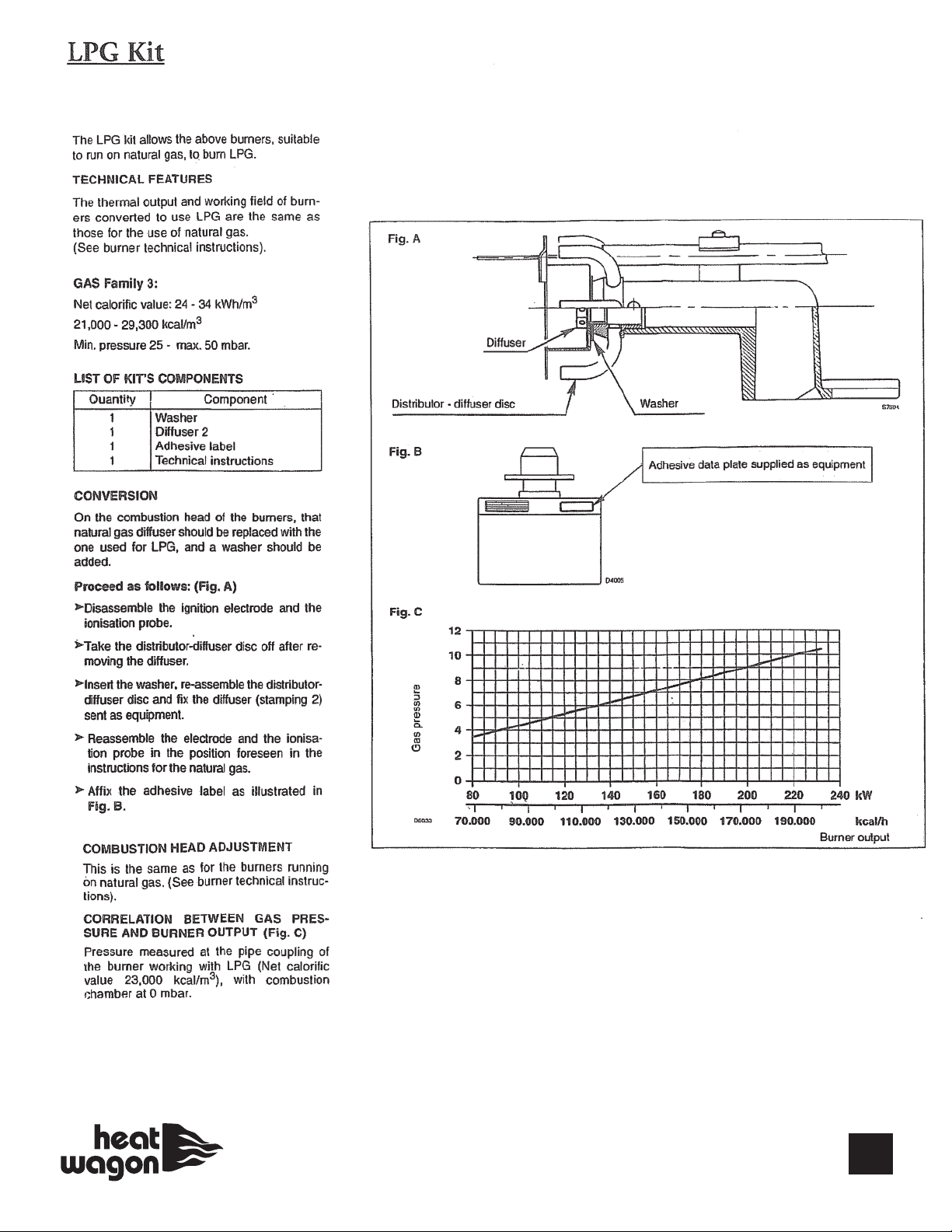
LPG it . . . . . . . . . . . . . . . . . . . . . . . . . . . . . . . . . . . . . . . . . . . . . . . . . . .10
Exhaust Flue Pipe Guidelines . . . . . . . . . . . . . . . . . . . . . . . . . . . . . . . . .11
Wiring Diagram . . . . . . . . . . . . . . . . . . . . . . . . . . . . . . . . . . . . . . . . . . . .12
Illustrated Parts Breakdown . . . . . . . . . . . . . . . . . . . . . . . . . . . . . . . .13-16
Riello Burner . . . . . . . . . . . . . . . . . . . . . . . . . . . . . . . . . . . . . . . . . . . .17-23
Installation and Maintenance Manual
Model VG600
Construction Heater
342 N. Co. Rd. 400 East • Val araiso, IN 46383
219-464-8818 • 888-432-8924 • Fax 800-255-7985
www.heatwagon.com
WARRANTY
This heater is guaranteed against defective materials and workmanship for one (1) year from Heat Wagon invoice
date.
Warranty repairs may be made only by an authorized, trained and certified Heat Wagon dealer. Warranty repairs
by other entities will not be considered. Warranty claims must include model number and serial number.
Components are guaranteed to the extent of the component manufacturer’s warranty.
LI ITATIONS
Warranty claims for service parts (wear parts) such as spark plugs, igniters, and flame rods will not be allowed.
Diagnostic parts such as voltage meters and pressure gauges are not warrantable. Evidence of improper fuel usage,
fuel pressures outside of manufacturer’s specification, poor fuel quality, improper electric power, misapplication
and/or evidence of abuse may be cause for rejection of warranty claims.
Labor, travel time, mileage and shipping charges will not be allowed. Minor adjustments to heaters are the respon-
sibility of the dealer. Defective parts must be tagged and held for possible return to the factory for 60 days from
date of repair. The factory will provide a return goods authorization, (RGA) for defective parts to be returned. No
warranty will be allowed for parts not purchased from Heat Wagon.
2

SAFETY & CAUTION
• Instructions given in this manual and the applicable regulations of the local authorities
must be followed.
• The unit may be operated only by those persons who have been instructed in its proper use.
• The unit is to be installed and operated in such a way as to ensure the safety of employees and
surroundings.
• Never cover the unit’s air openings.
• Always ensure adequate fresh air supply to the unit.
• Never stand in front of the discharge end of the heater.
• eep a minimum clearance of 10 feet from the fuel source. Storing and use of liquid fuel must
comply with the regulations and instructions given by the local authorities.
• Do not introduce foreign objects into the unit.
• Do not expose the unit to direct water jets.
• All electric cables outside the unit are to be protected against damage.
• Always disconnect the unit from power supply and turn off the gas supply when maintenance
or service is being performed.
• IF NOT OPERATED WITHIN GUIDELINES OF THESE OPERATING INSTRUCTIONS,
ANUFACTURER WILL NOT BE HELD RESPONSIBLE AND WARRANTY
WILL BECO E VOID.
3
SPECIFICATIONS
odel No. VG600
Fuels: Vapor Propane or Natural Gas
Capacity: 600,000 BTU/HR
Blower: 5400 CFM 3/4” SP
Electrical Rating: 120 Volts, 15 Amps
Fuel Consumption: NG-572 CFH / Propane-6.6 GPH
Gas Connection: 1” FNPT
Remote Thermostat: On/Off
Max. Discharge Temp.: 175ºF @ 0ºF Ambient
Duct Size: 20” Dia., 75 ft. max (straight), temp. rating 225ºF min.
Actual Dimensions: 90”L x 36”W x 54”H
Weight (approximate): 770 lbs.
Utilize Dedicated 20 Amp Service
Gas Supply: Inlet Pressure anifold Pressure Burner Orifice
ax W.C. in W.C. W.C.
Vapor Propane 14” W.C. 8” W.C. 2.8” 2.0
Natural Gas 14” W.C. 7” W.C. 2.8” 3.7
VF600
Fuel Supply: anifold Pressure (Fuel Pump) Burner Nozzle
151 psi 3.5 GPH x 60A
Note: 1 pound per square inch (psi) = 28” W.C. (water column)
Note: See page 14 for recommended duct, gas hose and pressure regulators.

OPERATING INSTRUCTIONS
INSTALLATION
• When transporting, use both lifting eyes located on sides of heater.
• Place the unit on a level and non-combustible surface.
• Minimum clearances from combustibles:
- outlet, minimum 10 feet
- sides, minimum 3 feet
- top, minimum 3 feet
- flue pipe exhaust minimum 2 feet
• If the unit is placed indoors, secure an adequate fresh air opening for the burner combustion air.
• The unit may not be installed and operated in premises where explosive or combustible fumes
or dust are present. Always check the regulations of local authorities.
• Be certain that neither the air inlet nor the air outlet is obstructed.
FUEL SUPPLY
For supply pressures greater than 1/2psi
• A regulator must be installed on the heater to ensure that the pressure to the
heater does not exceed 1/2 psi inlet pressure. Excessive pressures over 1/2 psi
(14” W.C.) will damage controls and void warranty.
• This heater is shipped as either natural gas or vapor propane. Check for proper burner orifice in
burner.
Vapor Propane 2.0
Natural Gas 3.7
• Be certain to use adequate hose or pipe size to ensure proper volume and pressure.
See Chart Below.
4
VAPOR PROPANE QUICK
REFERENCE HOSE
CHART
(Tank sizing chart
on page 9)
Hose BTU
Length 600,000
n Feet 1/2PSI 10PSI
10 3/4 3/8
25 1 3/8
35 1 3/8
50 1-1/4 3/8
75 1-1/4 1/2
100 1-1/4 1/2
125 1-1/4 1/2
150 1-1/4 1/2
175 1-1/2 3/4
200 1-1/2 3/4
225 1-1/2 3/4
NATURAL GAS QUICK
REFERENCE HOSE
CHART
Hose BTU
Length 600,000
n Feet 1/2PSI 1PSI 2PSI 5PSI
10 1 3/4 3/4 3/4
25 1-1/4 3/4 3/4 3/4
35 1-1/4 3/4 3/4 3/4
50 1-1/4 3/4 3/4 3/4
75 1-1/2 3/4 3/4 3/4
100 1-1/2 3/4 3/4 3/4
125 1-1/2 1 3/4 3/4
150 213/4 3/4
175 2 1-1/4 3/4 3/4
200 2 1-1/4 3/4 3/4
225 2 1-1/4 3/4 3/4

FUEL SUPPLY (CONTINUED)
• For proper propane tank sizing see page 9.
• Visually inspect the hose assembly and ensure that it is protected from traffic, building
materials, and contact with hot surfaces. If it is evident that there is excessive abrasion or wear,
or the hose is cut, replace it immediately.
• Purge air from line and wait 10 minutes for gas to dissipate.
• After installation, check the hose assembly for gas leaks by applying a water and soap solution
to each connection.
• Fuel hose must be UL approved.
• The installation of this heater to a natural gas supply must confirm with all applicable local
codes or, in the absence of local codes, with the National Fuel Ga Code ANSI Z223.1/NFPA 54.
For vapor propane, refer to standard for Storage and Handling of Liquified Petroleum Ga e
ANSI/NFPA 58.
ELECTRICAL
• Electric cable extensions must be connected based on the unit capacity and cable length.
• We highly recommend a dedicated line, 20 amp minimum.
• Confirm voltage at heater connection (105V min.) to ensure proper operation.
EXHAUST FLUE PIPE
• The unit is to be connected to a flue pipe with adequate draft, to ensure the proper start and
operation of the unit. Refer to page 11.
• The flue pipe and its installation must comply with the regulations and instructions given by
the local authorities.
• A flue pipe must be used at all times. You must increase flue pipe diameter if its is
longer than 26”
DISCHARGE DUCTING (Warm Air)
• Minimum clearance from combustible materials is 4 inches.
• Use steel ducting or fabric ducting capable of withstanding maximum temperature of 225ºF.
• Maximum length of duct: 75’ (straight).
• Duct diameter: 20”.
• Make sure that the duct is safely and properly fastened to the outlet.
• Avoid sharp bends and corners to ensure maximum air flow and avoid back pressure/heat
accumulation in heater.
• Do not exceed 3/4” w.c. of back pressure.
• FAILURE TO COMPLY WITH THESE RECOMMENDATIONS COULD RESULT IN SHUTDOWN
OF THE HEATER.
Rec Duct PN WD2025 (20’Dia. x 25’ Long)
5
6
START UP
• Only people trained in the operation and supervision of this heater should operate
and maintain the unit.
• Check the unit to make sure that there are no visible defects on the control and safety devices
and that the unit has been installed correctly.
1. Check that the control switch on the control box is in position “0” (STOP).
2. Pre-select desired room temperature on the remote thermostat. The temperature must be set
higher than the ambient temperature.
3. Open all possible shut-off devices of the fuel supply lines.
4. Turn the control switch on the control box to position “1” (HEATING).
5. When the ambient temperature level is low, the burner switches on automatically. The fan
does not switch on until the set temperature (104ºF) of the heat-exchanger has been
reached (will take approximately 1-5 minutes).
• After startup, the heater is operated automatically by the room thermostat and governed by all
control devices, including the safety limit controls.
• The room thermostat and burner sensor control the running sequences of the
burner and the fan sensor controls the fan function.
• Overheat limit reset controls and shuts off the heater (burner) in the case of overheating.
• The unit can also be used for ventilation purposes only, if needed.
1. Turn the control switch on the control box to position “2” (VENTILATION).
2. The unit is now in the continuous ventilating mode.
3. Heating is not possible in this mode.
SHUT DOWN
• Turn control switch to position “0” (STOP).
• If moving the heater, close fuel supply followed by turning control switch to position “0” (Stop).
Important!
The air supply fan continues running to cool down the combustion
chamber/heat exchanger and then stops later. The fan can restart for several
times before finally switching off!
WARNING!
UNIT AY BE UNPLUGGED IN E ERGENCY SITUATIONS ONLY. OTHERWISE,
DO NOT STOP THE UNIT BY UNPLUGGING IT. UNIT NEEDS TO COOL
DOWN USING ITS OWN FAN. FAILURE TO CO PLY WITH PROPER SHUT-
DOWN PROCEDURES CAN CAUSE DA AGE TO THE CO BUSTION
CHA BER, HEAT EXCHANGER, SAFETY FEATURES AND WILL VOID
WARRANTY.

AINTENANCE
Prior to starting any maintenance work be sure to disconnect unit from power supply after
the unit cools down fully and fan shuts off! (Shut Down Procedures page 6)
To ensure the proper function of the unit, it must be serviced on regular basis. Maintenance can
be performed, excluding the control devices and safety limit controls, by an authorized trained &
certified Heat Wagon dealer. The control devices and safety limit controls do not need routine
maintenance. If these items fail they must be replaced.
- Do not use any aggressive cleaning agents, which are harmful or environmentally unfriendly,
when cleaning the unit.
- Do not use water jet when cleaning the unit.
- Pressurized air may be used for maintenance. Be careful not to damage the fan blower wheel
with too much pressure (<30 psi).
- Check whether the unit is free from mechanical damage, replace faulty parts as necessary.
- Check fan blower wheel of the fan at regular intervals and clean it with a small
brush when needed, especially in a dusty (drywall) environment.
- Check functionality of control and safety devices regularly.
- Have the flue gas values of the burner checked regularly by authorized agents.
- Be sure to store the unit in a dust free and dry place when it is not used for a long period of
time. Cover the exhaust flue to prevent entry of foreign objects.
7

SERVICE
• The complete unit, including heat exchanger, combustion chamber and burner should be
cleaned from dust and dirt after every heating period, at a minimum of once per year.
-Removal of combustion chamber/heat exchanger:
For proper cleaning of the unit, manufacturer recommends removal of the access
panel of the heat exchanger. Clean combustion chamber and exchanger tube with
brush. Vacuum all loose ash and soot. Close all cleaning flanges carefully to avoid damage to
gasket material.
-Disassembling of burner:
1. Disassemble two tightening nuts on the combustion chamber flange and remove burner from
mounting flange. Take care not to damage the flange gasket.
2. Pull out the burner. Take care not to damage the burner head and power cable. Clean blower
wheel, ignitor electrode and flame sensor. Inspect the inside of the combustion
chamber.
8

9
REFERENCE CHARTS
10
Propane Orifice it
PN BIE 3000886
Natural Gas Orifice
PN BIE 3006703

EXHAUST FLUE PIPE GUIDELINES
CAPACITY OF TYPE B DOUBLE-WALL
VENTS SERVING A SINGLE DRAFT
HOOD-HEATER x 1000 BTU'S
FOR INDOOR APPLICATIONS
8101214
TOTAL
VENT
HEIGHT((HH))F
EET
LATERAL
LENGTH
((LL))FEET
60370 570 850 1170
2285 455 650 890
6273 435 630 870
12 255 406 610 840
80415 660 970 1320
2322 515 745 1020
8303 490 720 1000
16 281 458 685 950
10 0 450 720 1060 1450
2355 560 850 1130
10 330 525 795 1080
20 300 486 735 1030
15 0 525 840 1240 1720
2414 675 985 1350
15 373 610 905 1250
30 328 553 845 1180
20 0 575 930 1350 1900
2470 755 1100 1520
10 443 710 1045 1460
20 410 665 990 1390
30 380 626 945 1270
30 0 650 1060 1550 2170
2535 865 1310 1800
20 473 784 1185 1650
40 415 705 1075 1520
VENT DIAMETER (D) INCHES
F
11

WIRING CHART
12

13
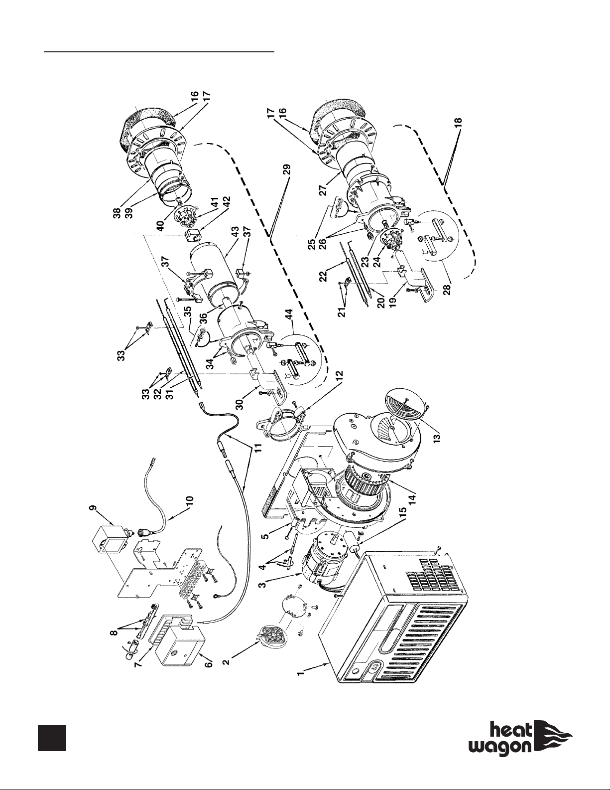
PARTS BREAKDOWN

14
PARTS LIST
ITEM # QTY PART # DESCRIPTION
$!!!""(
$!!
&!&
&"#
"
#!'
$!!$"%!
#!
&!
"$!##))#"&
###$!!
#
"$###
"##
"#
$!!
&!
"$#"
#%!
"$##
!"$#!
$"###"#"
#!#"&
"$!#
$##!
###&!
!##&!
$#"#!""
!##
#!$##
!&
#!&
$#$(
"%&
%#&
<,03>3 '$#
,03>3 '$#
%!#!
,03>3 #!!
!#!#
#"&
$!!
# #!"##""(
!$#!!
#!!#
#!!#
"&#!!
%!##"&#
"&#
$!!"&#
#!
""(#!"###
#""!"
& ?<@$#
"% !$#!?#<?$##"'#
"% !$#!?#<?$##"'#
15
SPARE PARTS BREAKDOWN
VG900
VG600
VG700
16
SPARE PARTS LIST
*705-#6*0348"/4;3
*<08641!-.91*846!%
""41-340,
93.7%*1:-

17
RIELLO BURNER - WIRING
-08/-6%46%+4386417=78-27

18
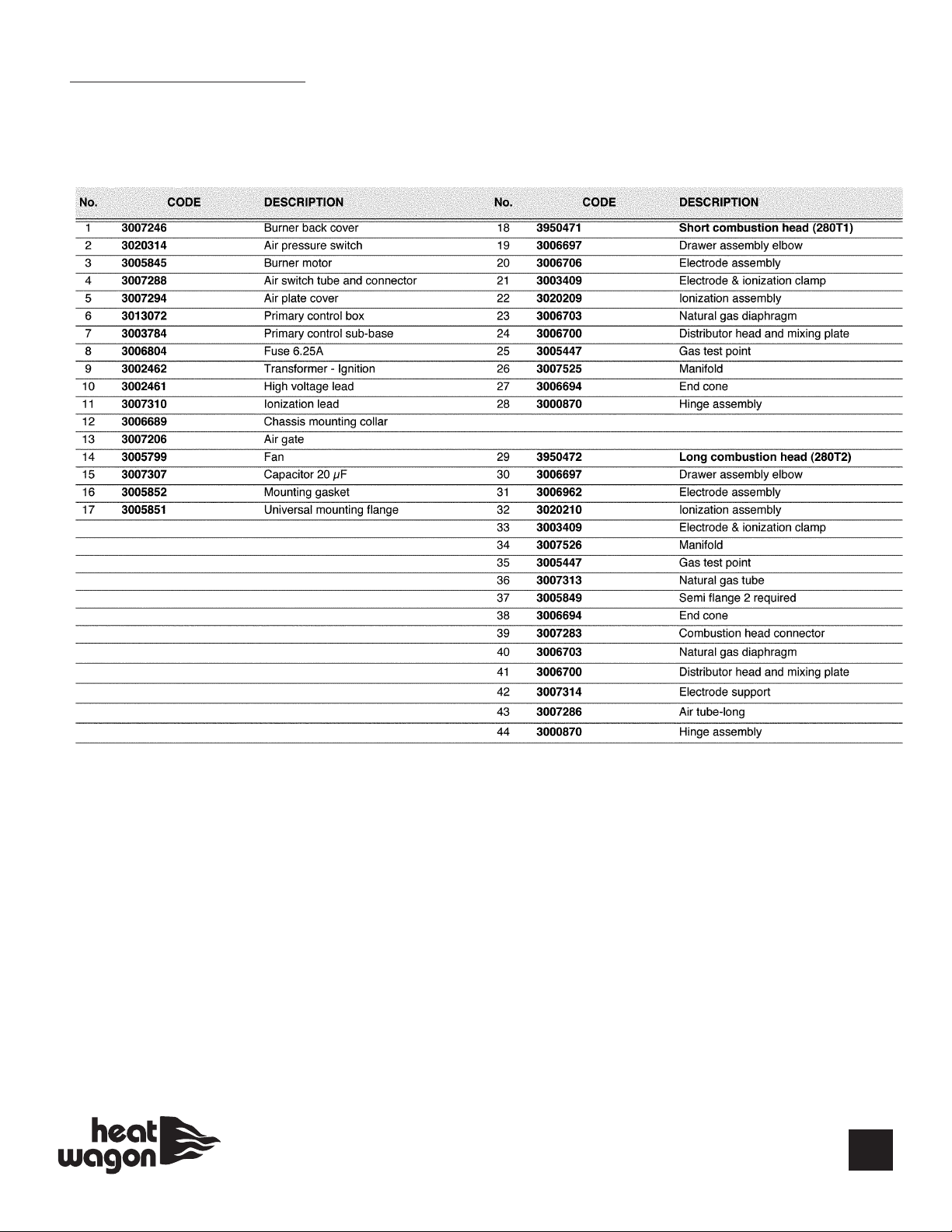
RIELLO BURNER - CO BUSTION HEAD
19
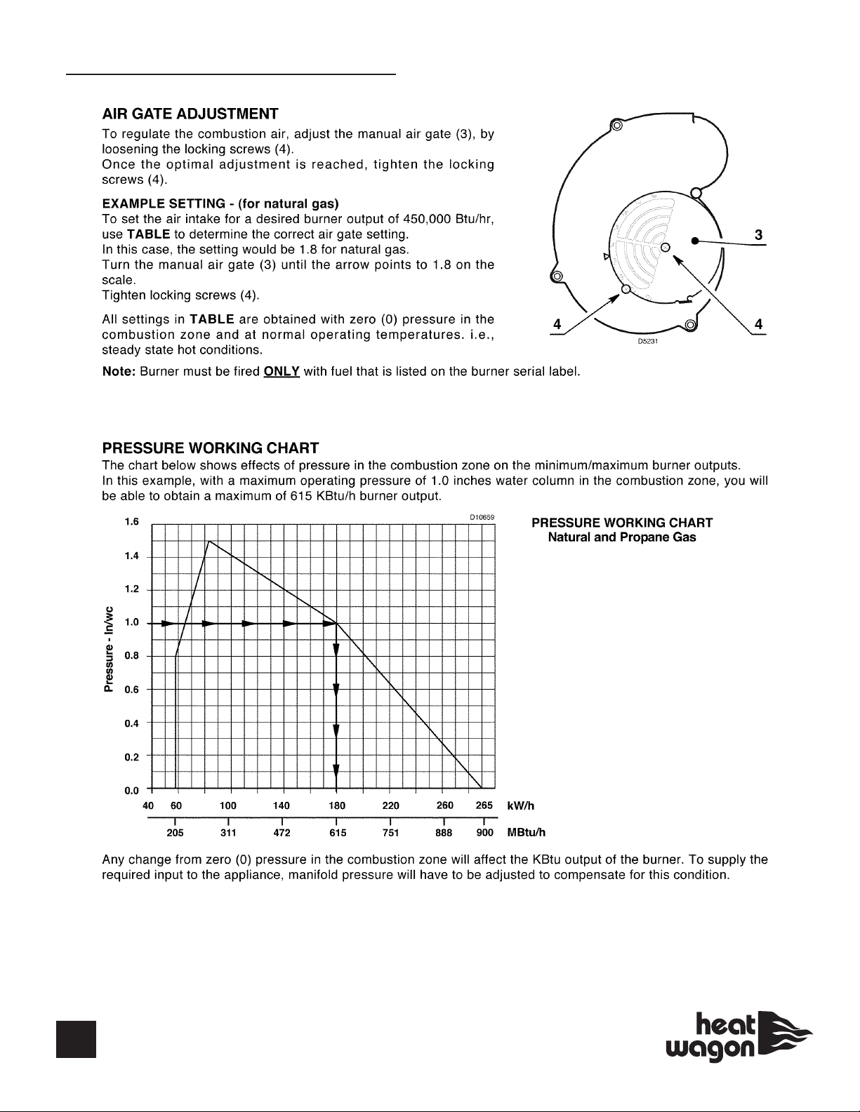
RIELLO BURNER - AIR GATE
This manual suits for next models
1
Table of contents
Other Heatwagon Heater manuals

Heatwagon
Heatwagon HVF110 Manual

Heatwagon
Heatwagon DF400 Manual

Heatwagon
Heatwagon VG400 Manual

Heatwagon
Heatwagon HVF110 User manual

Heatwagon
Heatwagon VF900SC The Dragon Wagon Manual

Heatwagon
Heatwagon 4200 Manual

Heatwagon
Heatwagon HRF115 Manual

Heatwagon
Heatwagon 21103000 Manual

Heatwagon
Heatwagon HVF210HD Manual

Heatwagon
Heatwagon 750NEF Manual

Heatwagon
Heatwagon Jumbo 600 Manual

Heatwagon
Heatwagon 1800 Manual

Heatwagon
Heatwagon VG1000 Manual
 Manual")
Heatwagon
Heatwagon 1800B(L) Manual

Heatwagon
Heatwagon DG250 Manual

Heatwagon
Heatwagon DG250 Manual

Heatwagon
Heatwagon S1505A Manual

Heatwagon
Heatwagon DG250 Manual

Heatwagon
Heatwagon 2730C Manual
 Manual")
Heatwagon
Heatwagon 950H(L) Manual


