HeBao CR-108D User manual

The Visionary Future of Digital Reality
KVM Product Series
User Manual
8-Port Combo Cat-5 Reach KVM Switch: CR-108D
16-Port Combo Cat-5 Reach KVM Switch: CR-116D
Cat-5 Server Module: UP-300 (Optional)
KVM Distribution System

2| HeBao Technology
www.hbdepot.com | 2
www.hbdepot.com |
3
Product Introduction
e Combo Cat-5 Reach KVM Switch allows advanced control over multiple computers using one set of keyboard, video
monitor, and mouse. One KVM console can control up to 8 or 16 computers in a single level setting, or up to 516~4096 com-
puters with a 3 level cascading capability.
Easy switching access is made possible through mouse-driven on-screen display (OSD) menu. OSD supports Auto Scan
feature to monitor each computer activities in a secured setting.e KVM console is pure hardware design without the hassle
of software conguration. By eliminating extra cost for storage, components, and electricity, Combo Cat-5 KVM Reach Switch
is the most cost eective solution to manage multiple computers.
Product Features
♦Use one KVM console to control 8/16 computers
♦Dual Interface - Support PS/2 and USB interfaces
♦Maximum distance between KVM and server is 300 meters over Cat5e/6 cable
♦Video gain control to adjust VGA quality over dierent distance
♦Support Hot-Swap - All devices connected to the KVM can be added or removed at any time
♦Pure hardware; No software required
♦Multiplatform support – Windows, Linux, Mac, Sun Micro System, DOS, FreeBSD
♦Maximum VGA resolution: 1920 x 1200@60Hz
♦Automatic KVM type detection for optimum setup
♦ree types of switching: Front Panel Push Button, Hot-Key, and OSD menu
♦OSD supports individual name, password, auto scan, reset, and monitor-sleeping function.
♦3 level cascading capability to connect up to 512~4096 computers
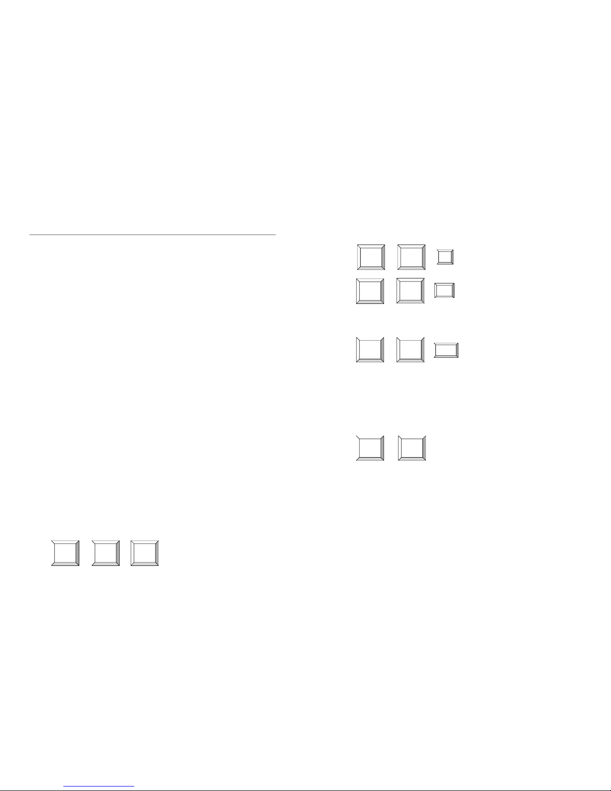
Panel Descriptions
1. VGA Port (KVM Console)
2. PS/2 Keyboard/Mouse Port
(KVM Console)
3. USB Keyboard/Mouse Port
(KVM Console)
4. Power Jack ( DC 9V )
5. RJ-45 System Link Port 1 to 8
1. PS/2 Mouse Port (To PC)
2. PS/2 Keyboard Port (To PC)
3. VGA Port (To PC)
4. RJ-45 System Link Port
5. System Link Status LEDs
6. PS/2 to USB Connector (For
connecting USB Keyboard/
Mouse Signals)
CR-108D and CR-116D is similar to one another, dierence in the number of System Link Ports
Green LED: On-Line
Yellow LED: Selected PC
▼CR-108D
▼Cat-5 Server Module: UP-300 (Optional)
➍➊➋ ➌ ➎
Auto Scan RESET
➎➊
➋
➏
➍
➌
4| HeBao Technology
www.hbdepot.com | 4
www.hbdepot.com |
5
b. Auto Scan: Press <Scroll Lock>+<Scroll Lock>+<F4> to automatically scan power-on computers. You may change
scan rate by go to the OSD screen and press <g> to change scan interval from 1-255 secs.
c. Manual Scan: Press <Scroll Lock>+<Scroll Lock>+<Space> to switch to the next power-on computer.
• On-Screen-Display Operation
a. You may start with two <Scroll Lock> keystrokes to activate OSD (On-Screen-Display) function. You can press
<h> or <i> to move to preferred computer and press <Enter>. If a channel is connected to a second-tier switch, its
front will show a “ u”to indicate a switch, you may press <Enter> to go to second-tier switch to select its connected
PCs. You can press <Esc> to leave OSD menu.
b. F1 (EDIT): After you activated OSD function, you can use <h> or <i> to move to preferred computer and press
<F1> to edit, you can use character A ~ Z, 0 ~ 9, “ - ”, “ `” and “ . ” You can use <F5> to clear or <Enter> to go to
next computer. After editing, you can press <F1> to save change.
c. Setup the Password for Administrator:
1. Server Module installation :
• For PS/2 + VGA interface: Connect UP-300’s three connectors to server’s PS/2 keyboard, VGA, and PS/2 mouse ports.
• For USB + VGA interface: Connect enclosed PS/2 to USB connector to keyboard connector, then plug it to server’s
USB port and don’t connect the PS/2 mouse connector. e USB connector will deliver both keyboard and mouse
signals. Lastly, connect VGA connector to server’s VGA port.
• Function Test: Power on servers; the power of server module will be supplied by PC’s PS/2 or USB port. e yellow
LED of RJ-45 port will turn on, and the green LED of RJ-45 port will be on if the connection of UTP cable is correct
and VGA signal is normal.e light will be o otherwise.
2. KVM Switch Installation :
• First Time Set-up: Please turn o all servers and plug the user console - keyboard, video monitor, and mouse - into
corresponding user port and then plug the power adapter into the switch. Keyboard and mouse can be PS/2 and/or USB
type. Connect CAT5/5e/6 UTP cable (Use 568B Standard) between PC and Server Module’s System Link port. Lastly,
turn on all PCs.
• e light of panel will blink one time in the beginning to make sure all connection is normal.
• If you face any signal problem during any part of installation or operation, you can press last two buttons of the front-
panel to reset the system. e keyboard and front panel LEDs will blink to correspond with the action of reset.
• You may use enclosed rack mount kit in order to install switch on the 19’ rack.
3. KVM Switch Operation :
• Front Panel Push Buttons
a. You may select a computer by pressing the front panel push button. If the channel is connected to a power-on com-
puter, the front panel LED will display green. If any channel displays yellow LED, it reects the selected computer.
If a second-tier switch is connected, when you switch to a PC on the second-tier, the corresponding channel led on
the rst-tier will also display yellow to conrm the selection.
b. Auto Scan: By pressing the rst-tier switch’s push button <1> and <2>, you can activate Auto Scan function to scan
power-on computers.
c. Reset: By pressing last two buttons of front-panel to reset the system, the keyboard and front panel LEDs will blink
to correspond with the action of reset.
• Hot-key Commands
a. You may start with two <Scroll Lock> keystrokes followed by number keystroke <1> to <8>or<A> to <H> switch
over 8/16 computers. After you activate hot-key function, the OSD menu will show on the screen and then followed
by typing the channel number to switch. If you connected additional tier of switches, you should input two-digit
number to switch. Ex: Press <Scroll Lock>+<Scroll Lock>+<1>+<8> to switch to PC No. 8 of second-tier switch
No. 1.
Installation and Operation
Scroll
Lock
Scroll
Lock
1~8or
A~H
Scroll
Lock
Scroll
Lock F4
Scroll
Lock
Scroll
Lock Esc
+ + = Switch to selected channel
+ + = Auto scan
+ + = Stop Auto Scan
Scroll
Lock
Scroll
Lock Space
+ + = Switch to next power-on PC
+ = To activate OSD menu
1. Under OSD function, press <g> + <F2> to setup the password for Administrator. Please be noted that you
need to setup this password before setting the password for general users.
2. After setting the password for Administrator, you will need to assign the password for general users in each
channel, and it can be dierent in each channel.
3. For the channel without setting the password for general users, it will be required to input the Administrator
password.
4. By skipping the setup of Administrator password, you can refer to the next section D. to setup general password.
Scroll
Lock
Scroll
Lock
6| HeBao Technology
www.hbdepot.com | 6
www.hbdepot.com |
7
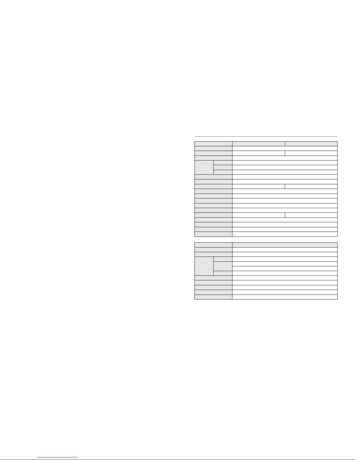
Specications
Model / Order No. CR-108D CR-116D
Model Name 8/16-Port Combo Cat-5 Reach KVM Switch
PC Connections 8 16
KVM Ports RJ-45
PC Ports
Monitor HDB-15 (Female)
Keyboard 6 pin mini-Din (Female), USB Type A (Female)
Mouse 6 pin mini-Din (Female), USB Type A (Female)
Multiplatform Windows, Linux, Mac, Sun Micro System, DOS, FreeBSD
LED Display Green LED: On-Line Yellow LED: Selected PC
Push Button 8 16
Switch Methods Push Button, Hot-Key, OSD Menu
Auto Scan Interval 1~255 Seconds
Maximum VGA Resolution 1920 x 1200 at 60Hz
Power Adaptor DC 9V, 1.5A
Casing Metal
Weight 2.3 kg 2.9 kg
Dimension (LxWxH in mm) 438 x 180 x 44
Operating Temp. 0° C ~50° C
Storage Temp. 0° C ~60° C
Humidity 25%~70% Non-Condensing
Model / Order No. UP-300
Model Name Cat-5 Server Module
KVM Ports RJ-45
PC Ports
Monitor HDB-15 (Male)
Keyboard 6 pin mini-Din (Male)
Via PS/2 to USB Connector you can switch PS/2 signal to USB type
Mouse 6 pin mini-Din (Male)
LED Display Green: Linked Yellow: On-Line
Casing Plastic
Power Supply By PS/2 or USB Port
Weight 120g
Dimension (LxWxH in mm) 78 x 32x 19, PS/2 & Mouse cable 330mm
d. F2 (PSW): After you activated OSD function, you can use <h> or <i> to move to preferred computer and press
<F2> to set general password. For a password protected computer, it will show a “F”symbol. When you go to the
computer next time, it will show a small window for you to enter password. If you want to cancel or change the
password, please enter OSD menu and press <F2> in that computer channel. By not entering any character, you can
cancel the password or enter new password to activate password protect.
e. F3 (Scan Set): After you activate OSD function, you can use <h> or <i> to move to preferred computer and press
<F3> to set the computer you want to scan. It will show a clock symbol to identify the computer.
f. F4 (Auto-Scan): After you activate OSD function, you can press <g> to set the scan Interval from 1 to 255 seconds
and press <Enter> to save change.
g. Monitor-Sleeping: After you activate OSD function, you can press <g> to set Monitor-sleeping mode starts from 1
to 255 seconds and press <Enter> to save change.
h. VGA Quality Adjustment: Build-in 21 position adjustments. After you activate OSD function, you can press <+>
and <-> on the top of keyboard to modify the best VGA Quality. If you would like to clear setup, you can press the
8th button and plug-in the power adapter again.
i. Channel Display: When you switch to dierent computer, it will show the channel ID and computer name on the
screen and disappeared after 3 seconds.
j. During operation, if one computer has been turned o or added, the status will not change in your current OSD
menu. Restart your OSD to display the corrected status.

8| HeBao Technology www.hbdepot.com | 8
HeBao Technology
No. 35, LN 32, GuanFu S.RD., SongShan District, Taipei City, Taiwan
Tel:+886 2 2577-1828
Fax: +886 2 2577-1829
www.hbdepot.com
This manual suits for next models
2
Table of contents
Popular Switch manuals by other brands

A-Neuvideo
A-Neuvideo ANI-8PDU-24V instruction manual

Planet
Planet GS-5220 Series Quick installation guide

Multitech
Multitech RouteFinder RF102S quick start guide

Tripp Lite
Tripp Lite NetController B040-008-19 owner's manual

SMART-AVI
SMART-AVI HDR16X16 user manual

Tripp Lite
Tripp Lite B006-HD2UA2 quick start guide


