Hectronic H6052 Operating and maintenance manual

H6052 Hardware Reference Guide
1
H6052
Hardware Reference Guide
HECTRONIC AB
Box 3002
SE-750 03 UPPSALA
SWEDEN
TEL: +46 (0)18 660 700
FAX: +46 (0)18 660 701
EMAIL: info@hectronic.se
WEB: www.hectronic.se

H6052 Hardware Reference Guide
2
Content
Copyright ................................................................................................................................................. 4
Trademarks .............................................................................................................................................. 4
FCC and DOC Statement on Class B ......................................................................................................... 4
Warranty ................................................................................................................................................. 5
Static Electricity Preca tions ................................................................................................................... 5
Safety Meas res ...................................................................................................................................... 5
Chapter 1 – Introd ction ......................................................................................................................... 6
Specifications ........................................................................................................................... 6
Features ................................................................................................................................... 7
Chapter 2 - Hardware Installation ........................................................................................................... 8
Board Layout ............................................................................................................................ 8
Mechanical Diagram ................................................................................................................. 9
System Memory ..................................................................................................................... 1
Installing the DIM Mod le ........................................................................................................................... 10
Jumper Settings ...................................................................................................................... 13
Clear CMOS Data ......................................................................................................................................... 13
Connectors ............................................................................................................................. 14
CPU Fan Connector ...................................................................................................................................... 14
COM Express Connectors ............................................................................................................................ 15
Standby Power LED ................................................................................................................ 18
Cooling Option ....................................................................................................................... 22
Heat Sink with Cooling Fan ..................................................................................................... 22
Dimensions .................................................................................................................................................. 23
Installing H6 52 onto a Carrier Board ...................................................................................... 25
Chapter 3 - BIOS Set p .......................................................................................................................... 28
Overview ............................................................................................................................... 29
Defa lt Config ration .................................................................................................................................. 29
Entering the BIOS Set p Utility .................................................................................................................... 29
Legends ........................................................................................................................................................ 30
Scroll Bar ...................................................................................................................................................... 30
S bmen ...................................................................................................................................................... 30
AMI BIOS Setup Utility ............................................................................................................ 31
Main ............................................................................................................................................................. 31
Advanced ..................................................................................................................................................... 32
North Bridge ................................................................................................................................................ 47
Boot ....................................................................................................................................... 52

H6052 Hardware Reference Guide
3
Security .................................................................................................................................. 54
Save & Exit ............................................................................................................................. 56
Appendix A - Watchdog Sample Code ................................................................................................... 57
Appendix B – Tro bleshooting .............................................................................................................. 58
Troubleshooting Checklist ...................................................................................................... 58
Monitor/Display ..................................................................................................................... 58
Power Supply ......................................................................................................................... 59
Floppy Drive ........................................................................................................................... 59
Hard Drive .............................................................................................................................. 6
Serial Port .............................................................................................................................. 6
Keyboard ............................................................................................................................... 6
System Board ......................................................................................................................... 61

H6052 Hardware Reference Guide
4
Copyright
This publication contains information that is protected by copyright. No part of it may be
reproduced in any form or by any means or used to make any transformation/adaptation
without the prior written permission from the copyright holders.
This publication is provided for informational purposes only. The manufacturer makes no
representations or warranties with respect to the contents or use of this manual and
specifically disclaims any express or implied warranties of merchantability or fitness for any
particular purpose. The user will assume the entire risk of the use or the results of the use of
this document. Further, the manufacturer reserves the right to revise this publication and
make changes to its contents at any time, without obligation to notify any person or entity of
such revisions or changes.
© 2010. All Rights Reserved.
Trademarks
Product names or trademarks appearing in this manual are for identification purpose only
and are the properties of the respective owners.
FCC and DOC Statement on Class B
This equipment has been tested and found to comply with the limits for a Class B digital
device, pursuant to Part 15 of the FCC rules. These limits are designed to provide
reasonable protection against harmful interference when the equipment is operated in a
residential installation. This equipment generates, uses and can radiate radio frequency
energy and, if not installed and used in accordance with the instruction manual, may cause
harmful interference to radio communications. However, there is no guarantee that
interference will not occur in a particular installation. If this equipment does cause harmful
interference to radio or television reception, which can be determined by turning the
equipment off and on, the user is encouraged to try to correct the interference by one or
more of the following measures:
Reorient or relocate the receiving antenna.
Increase the separation between the equipment and the receiver.
Connect the equipment into an outlet on a circuit different from that to which the
receiver is connected.
Consult the dealer or an experienced radio TV technician for help.
Notice:
1. The changes or modifications not expressly approved by the party responsible for
compliance could void the user’s authority to operate the equipment.
2. Shielded interface cables must be used in order to comply with the emission limits.

H6052 Hardware Reference Guide
5
Warranty
1. Warranty does not cover damages or failures that are due to misuse of the product,
inability to use the product, unauthorized replacement or alteration of components
and product specifications.
2. The warranty is void if the product has been subjected to physical abuse, improper
installation, modification, accidents or unauthorized repair of the product.
3. Unless otherwise instructed in this user’s manual, the user may not, under any
circumstances, attempt to perform service, adjustments or repairs on the product,
whether in or out of warranty. It must be returned to the purchase point, factory or
authorized service agency for all such work.
4. We will not be liable for any indirect, special, incidental or consequential damages to
the product that has been modified or altered.
Static Electricity Precautions
It is quite easy to inadvertently damage your PC, system board, components or devices even
before installing them in your system unit. Static electrical discharge can damage computer
components without causing any signs of physical damage. You must take extra care in
handling them to ensure against electrostatic build-up.
1. To prevent electrostatic build-up, leave the system board in its anti-static bag until
you are ready to install it.
2. Wear an antistatic wrist strap.
3. Do all preparation work on a static-free surface.
4. Hold the device only by its edges. Be careful not to touch any of the components,
contacts or connections.
5. Avoid touching the pins or contacts on all modules and connectors. Hold modules or
connectors by their ends.
Important:
Electrostatic discharge (ESD) can damage your processor, disk drive and other
components. Perform the upgrade instruction procedures described at an ESD
workstation only. If such a station is not available, you can provide some ESD
protection by wearing an antistatic wrist strap and attaching it to a metal part of the
system chassis. If a wrist strap is unavailable, establish and maintain contact with the
system chassis throughout any procedures requiring ESD protection.
Safety Measures
To avoid damage to the system:
Use the correct AC input voltage range.
To reduce the risk of electric shock:
Unplug the power cord before removing the system chassis cover for installation or
servicing. After installation or servicing, cover the system chassis before plugging the
power cord.
H6052 Hardware Reference Guide
6
Chapter 1 – Introduction
Specifications
Processor
Intel® CoreTM i7-610E (SV)
Intel® i7-620LE (LV)
Intel® i7-620UE (ULV)
Intel® CoreTM i5-520E (SV)
Intel® Celeron® P4505 (SV)
Processor package: BGA1288
Chipset
One 204-pin SODIMM socket
Supports 800/1066MHz DDR3 SDRAM
Supports maximum of 4GB system memory
DRAM device technologies: 1Gb and 2Gb DDR3 DRAM
technologies are supported for x8 and x16 devices,
unbuffered, non-ECC
System Memory
One 204-pin SODIMM socket
Supports 800/1066MHz DDR3 SDRAM
Supports maximum of 4GB system memory
DRAM device technologies: 1Gb and 2Gb DDR3 DRAM
technologies are supported for x8 and x16 devices,
unbuffered, non-ECC
Graphics
Intel® Gen5.75 integrated graphics engine
Supports LVDS and VGA
Intel® Clear Video technology
Intel® Dynamic Video Memory Technology (Intel® DVMT)
Intel® Smart 2D Display Technology (Intel® S2DDT)
Audio
Realtek ALC262 High Definition audio interface
LAN
Intel 82577LM Gigabit LAN PHY
Integrated 10/100/1000 transceiver
Fully compliant with IEEE 802.3, IEEE 802.3u, IEEE
802.3ab
Supports wire management
Serial ATA
4 Serial ATA ports
Data transfer rate up to 3Gb/s
Integrated Advanced Host Controller Interface (AHCI)
controller
IDE
Supports up to two IDE devices
DMA mode: Ultra ATA up to 100MB/s
PIO mode: up to 16MB/s
Expansion Interfaces
Supports 8 USB ports (USB 1.1/2.0 host controllers)
Supports up to 4 PCI slots (PCI 2.3 interface)
H6052 Hardware Reference Guide
7
Supports PCIE x16 / SDVO / HDMI / Display Port
switchable interface
Supports 4 PCIE x1 interface
Supports LPC interface
Supports 8-bit Digital I/O
Damage Free
Intelligence
Monitors CPU temperature and overheat alarm
Monitors CPU fan speed and failure alarm
Monitors Vcore/VGFX/1.5V voltages and failure alarm
Watchdog timer function
BIOS
32Mbit SPI BIOS
Temperature
0°C to 60°C
Humidity
10% to 90%
Power
Input: 12V, 5VSB, VCC_RTC
Regulatory
EMC: CE, FCC Part 15 Class B
PCB
Dimensions
- COM Express Compact form factor
- 9.5cm (3.74”) x 9.5cm (3.74”)
Compliance
- PICMG COM Express R1.0 basic form factor, Type 2
Features
Watchdog Timer
The Watchdog Timer function allows your application to regularly “clear” the system at the
set time interval. If the system hangs or fails to function, it will reset at the set time interval so
that your system will continue to operate.
DDR3
DDR3 delivers increased system bandwidth and improved performance. The advantages of
DDR3 are its higher bandwidth and its increase in performance at a lower power than DDR2.
Graphics
The integrated Intel Gen 5.75 graphics engine delivers an excellent blend of graphics
performance and features to meet business needs. It provides excellent video and 3D
graphics with outstanding graphics responsiveness. These enhancements deliver the
performance and compatibility needed for today’s and tomorrow’s business applications.
Serial ATA
Serial ATA is a storage interface that is compliant with SATA 1.0a specification. With speed
of up to 3GB/s, it improves hard drive performance faster than the standard parallel ATA
whose data transfer rate is 100MB/s.
Gigabit LAN
The Intel 82577LM Gigabit LAN controller supports up to 1Gbps data transmission.
H6052 Hardware Reference Guide
8
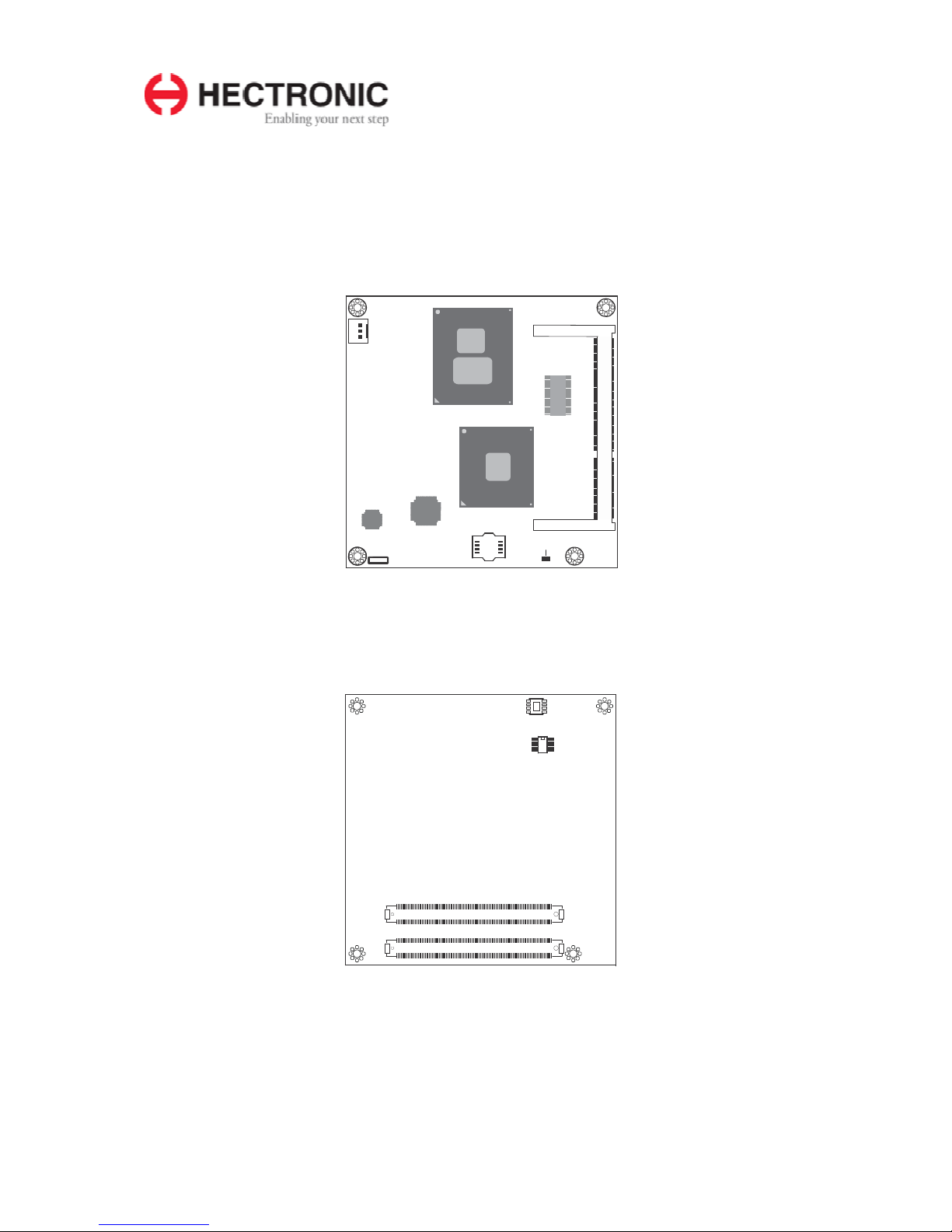
DD
R3
SODIMM
D1
D110
COM Express
con n e ct o r
C1
C110
B1
B110
COM E xpress con n e ct o r
A1
A110
1
CPU fan
JMicron
JMB368
SPI
F ash
BIOS
Inte
82 577LM
Standby
Power
LED
1
C ear C MOS
(J P1)
Intel
HM55
Intel CPU
Chapter 2 - Hardware Installation
Board Layout
Top view
Bottom view

H6052 Hardware Reference Guide
9
Mechanical Diagram

H6052 Hardware Reference Guide
10
DDR3
socket
Standby
Power LED
Important:
Electrostatic discharge (ESD) can damage your board, processor, disk drives, add-
in boards, and other components. Perform installation procedures at an ESD
workstation only. If such a station is not available, you can provide some ESD
protection by wearing an antistatic wrist strap and attaching it to a metal part of the
system chassis. If a wrist strap is unavailable, establish and maintain contact with
the system chassis throughout any procedures requiring ESD protection.
System Memory
The system board is equipped with two 204-pin SODIMM sockets that support DDR3
memory modules.
Important:
When the Standby Power LED lit red, it indicates that there is power on the board.
Power-off the PC then unplug the power cord prior to installing any devices. Failure
to do so will cause severe damage to the board and components.

H6052 Hardware Reference Guide
11
Installing the DIM Module
Note:
The system board used in the following illustrations may not resemble the actual one. These
illustrations are for reference only.
1. Make sure the PC and all other peripheral devices connected to it has been powered
down.
2. Disconnect all power cords and cables.
3. Locate the SODIMM socket on the system board.
4. Note the key on the socket. The key ensures the module can be plugged into the
socket in only one direction.
5. Grasping the module by its edges, align the module into the socket at an approximately
30 degrees angle. Apply firm even pressure to each end of the module until it slips
down into the socket. The contact fingers on the edge of the module will almost
completely disappear inside the socket.

H6052 Hardware Reference Guide
12
C ip
C ip
6. Push down the module until the clips at each end of the socket lock into position. You
will hear a distinctive “click”, indicating the module is correctly locked into position.

H6052 Hardware Reference Guide
13
1
2
3
1
2
3
1
-
2
On:
Norma
(defau t)
2-3 On:
C ear CMOS Data
JP1
Jumper Settings
Clear CMOS Data
If yo enco nter the following,
a. CMOS data becomes corrupted.
b. You forgot the supervisor or user password.
you can reconfigure the system with the default values stored in the ROM BIOS.
To load the default values stored in the ROM BIOS, please follow the steps below.
1. Power-off the system and unplug the power cord.
2. Set pins 2 and 3 to On. Wait for a few seconds and set the jumper back to its default
setting, pins 1 and 2 On.
3. Now plug the power cord and power-on the system.

H6052 Hardware Reference Guide
14
Se
nse
Power
Ground
3
1
Connectors
CPU Fan Connector
Connect the CPU fan’s cable connector to the CPU fan connector on the board. The cooling
fan will provide adequate airflow throughout the chassis to prevent overheating the CPU and
board components.
BIOS Setting
“Module Board H/W Monitor” submenu in the Advanced menu of the BIOS will display the
current speed of the cooling fan. Refer to chapter 3 of the manual for more information.

H6052 Hardware Reference Guide
15
A1
A110
COM
Express
Connectors
D1
D110
CO M E xp r ess
co nne cto r
C1
C110
B1
B110
CO M E xp r ess
co nne cto r
COM Express Connectors
The COM Express connectors are used to interface the H6052 COM Express board to a
carrier board. Connect the COM Express connectors (located on the solder side of the
board) to the COM Express connectors on the carrier board.
Refer to the “Installing H6052 onto a Carrier Board” section for more information.
Refer to the following pages for the pin functions of these connectors.
H6052 Hardware Reference Guide
16
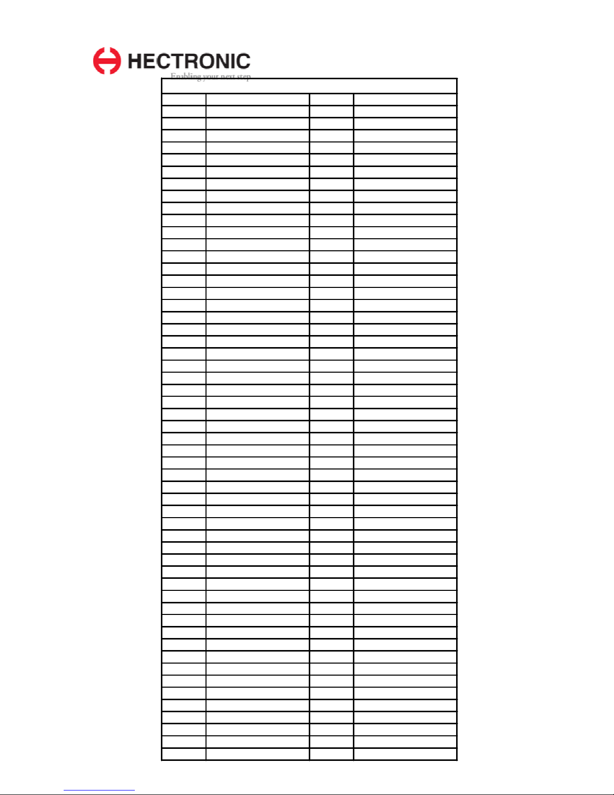
Row
A
1
GNDA1
56
NC
2
GBE0_MDI3-
57
GBD
3
GBE0_MDI3+
58
PCIE_TX3+
4
GNE0_LINK100#
59
PCIE_TX3-
5
GBE0_LINK1000#
60
GNDA7
6
GBE0_MDI2-
61
PCIE_TX2+
7
GBE0_MDI2+
62
PCIE_TX2-
8
NC
63
GPI1
9
GBE0_MDI1-
64
PCIE_TX1+
10
GBE0_MDI1+
65
PCIE_TX1-
11
GNDA2
66
GNDA8
12
GBE0_MDI0-
67
GPI2
13
GBE0_MDI0+
68
PCIE_TX0+
14
GBE0_CTREF
69
PCIE_TX0-
15
SUS_S3#
70
GNDA9
16
SATA0_TX+
71
LVDS_A0+
17
SATA0_TX-
72
LVDS_A0-
18
SUS_S4#
73
LVDS_A1+
19
SATA0_RX+
74
LVDS_A1-
20
SATA0_RX-
75
LVDS_A2+
21
GNDA3
76
LVDS_A2-
22
SATA2_TX+
77
LVDS_VDD_EN
23
SATA2_TX-
78
LVDS_A3+
24
SUS_S5#
79
LVDS_A3-
25
SATA2_RX+
80
GNDA10
26
SATA2_RX-
81
LVDS_A_CK+
27
BATLOW#
82
LVDS_A_CK-
28
ATA_ACT#
83
LVDS_I2C_CK
29
AC_SYNC
84
LVDS_I2C_DAT
30
AC_RST#
85
GPI3
31
GNDA4
86
KBD_RST#
32
AC_BITCLK
87
KBD_A20GATE
33
AC_SDOUT
88
PCIE0_CK_REF+
34
BIOS_DISABLE#
89
PCIE1_CK_REF-
35
THRMTRIP#
90
GNDA11
36
USB6-
91
RSVDA1
37
USB6+
92
NC
38
USB67_OC#
93
GPO0
39
USB4-
94
NC
40
USB4+
95
NC
41
GNDA5
96
GNDA12
42
USB2-
97
VCC_12VA1
43
USB2+
98
VCC_12VA2
44
USB23_OC#
99
VCC_12VA3
45
USB0- 100 GNDA13
46
USB0+ 101 VCC_12VA4
47
VCC_RTC 102 VCC_12VA5
48
EXCD0_PERST# 103 VCC_12VA6
49
EXCD0_CPPE# 104 VCC_12VA7
50
LPC_SERIRQ 105 VCC_12VA8
51
GNDA6 106 VCC_12VA9
52
NC 107 VCC_12VA10
53
NC 108 VCC_12VA11
54
GPI0 109 VCC_12VA12
55
NC 110 GNDA14
H6052 Hardware Reference Guide
17
Row
B
1
GNDB1
56
NC
2
GBE0_ACT#
57
GPO2
3
LPC_FRAME#
58
PCIE_RX3+
4
LPC_AD0
59
PCIE_RX3-
5
LPC_AD1
60
GNDB7
6
LPC_AD2
61
PCIE_RX2+
7
LPC_AD3
62
PCIE_RX2-
8
LPC_DRQ0#
63
GPO3
9
LPC_DRQ1#
64
PCIE_RX1+
10
LPC_CLK
65
PCIE_RX1-
11
GNDB2
66
WAKE0#
12
PWRBTN#
67
WAKE1#
13
SMB_CK
68
PCIE_RX0+
14
SMB_DAT
69
PCIE_RX0-
15
SMB_ALERT#
70
GNDB8
16
SATA1_TX+
71
LVDS_B0+
17
SATA1_TX-
72
LVDS_B0-
18
SUS_STAT#
73
LVDS_B1+
19
SATA1_RX+
74
LVDS_B1-
20
SATA1_RX-
75
LVDS_B2+
21
GNDB3
76
LVDS_B2-
22
SATA3_TX+
77
LVDS_B3+
23
SATA3_TX-
78
LVDS_B3-
24
PWR_OK
79
LVDS_BKLT_EN
25
SATA3_RX+
80
GNDB9
26
SATA3_RX-
81
LVDS_B_CK+
27
WDT
82
LVDS_B_CK-
28
AC_SDIN2
83
LVDS_BKLT_CTRL
29
AC_SDIN1
84
VCC_5V_SBYB1
30
AC_SDIN0
85
VCC_5V_SBYB2
31
GNDB4
86
VCC_5V_SBYB3
32
SPKR
87
VCC_5V_SBYB4
33
I2C_CK
88
NC
34
I2C_DAT
89
VGA_RED
35
THRM#
90
GNDB10
36
USB7-
91
VGA_GREEN
37
USB7+
92
VGA_BLUE
38
USB45_OC#
93
VGA_HSYNC
39
USB5-
94
VGA_VSYNC
40
USB5+
95
VGA_I2C_CK
41
GNDB5
96
VGA_I2C_DAT
42
USB3-
97
TV_DAC_A
43
USB3+
98
TV_DAC_B
44
USB01_OC#
99
TV_DAC_C
45
USB1- 100 GNDB11
46
USB1+ 101 VCC_12VB1
47
EXCD1_PERST# 102 VCC_12VB2
48
EXCD1_CPPE# 103 VCC_12VB3
49
SYS_RESET# 104 VCC_12VB4
50
CB_RESET# 105 VCC_12VB5
51
GNDB6 106 VCC_12VB6
52
NC 107 VCC_12VB7
53
NC 108 VCC_12VB8
54
GPO1 109 VCC_12VB9
55
NC 110 GNDB12

H6052 Hardware Reference Guide
18
Row
C
1
GNDC1
56
PEG_RX1-
2
IDE_D7
57
NC
3
IDE_D6
58
PEG_RX2+
4
IDE_D3
59
PEG_RX2-
5
IDE_D15
60
GNDC7
6
IDE_D8
61
PEG_RX3+
7
IDE_D9
62
PEG_RX3-
8
IDE_D2
63
NC
9
IDE_D13
64
NC
10
IDE_D1
65
PEG_RX4+
11
GNDC2
66
PEG_RX4-
12
IDE_D14
67
NC
13
IDE_IORDY
68
PEG_RX5+
14
IDE_IOR#
69
PEG_RX5-
15
PCI_PME#
70
GNDC8
16
PCI_GNT2#
71
PEG_RX6+
17
PCI_REQ2#
72
PEG_RX6-
18
PCI_GNT1#
73
SDVOB_CTRLDATA
19
PCI_REQ1#
74
PEG_RX7+
20
PCI_GNT0#
75
PEG_RX7-
21
GNDC3
76
GNDC9
22
PCI_REQ0#
77
NC
23
PCI_RESET#
78
PEG_RX8+
24
PCI_AD0
79
PEG_RX8-
25
PCI_AD2
80
GNDC10
26
PCI_AD4
81
PEG_RX9+
27
PCI_AD6
82
PEG_RX9-
28
PCI_AD8
83
DDPC_CTRLDATA
29
PCI_AD10
84
GNDC11
30
PCI_AD12
85
PEG_RX10+
31
GNDC4
86
PEG_RX10-
32
PCI_AD14
87
GNDC12
33
PCI_C/BE1#
88
PEG_RX11+
34
PCI_PERR#
89
PEG_RX11-
35
PCI_LOCK#
90
GNDC13
36
PCI_DEVSEL#
91
PEG_RX12+
37
PCI_IRDY#
92
PEG_RX12-
38
PCI_C/BE2#
93
GNDC14
39
PCI_AD17
94
PEG_RX13+
40
PCI_AD19
95
PEG_RX13-
41
GNDC5
96
GNDC15
42
PCI_AD21
97
NC
43
PCI_AD23
98
PEG_RX14+
44
PCI_C/BE3#
99
PEG_RX14-
45
PCI_AD25 100 GNDC16
46
PCI_AD27 101 PEG_RX15+
47
PCI_AD29 102 PEG_RX15-
48
PCI_AD31 103 GNDC17
49
PCI_IRQA# 104 VCC_12VC1
50
PCI_IRQB# 105 VCC_12VC2
51
GNDC6 106 VCC_12VC3
52
PEG_RX0+ 107 VCC_12VC4
53
PEG_RX0- 108 VCC_12VC5
54
NC 109 VCC_12VC6
55
PEG_RX1+ 110 GNDC18
H6052 Hardware Reference Guide
19
Row
D
1
GNDD1
56
PEG_TX1-
2
IDE_D5
57
NC
3
IDE_D10
58
PEG_TX2+
4
IDE_D11
59
PEG_TX2-
5
IDE_D12
60
GNDD7
6
IDE_D4
61
PEG_TX3+
7
IDE_D0
62
PEG_TX3-
8
IDE_REQ#
63
NC
9
IDE_IOW#
64
NC
10
IDE_ACK#
65
PEG_TX4+
11
GNDD2
66
PEG_TX4-
12
IDE_IRQ
67
GNDD8
13
IDE_A0
68
PEG_TX5+
14
IDE_A1
69
PEG_TX5-
15
IDE_A2
70
GNDD9
16
IDE_CS1#
71
PEG_TX6+
17
IDE_CS3#
72
PEG_TX6-
18
IDE_RESET#
73
SDVOB_CTRLCLK
19
PCI_GNT3#
74
PEG_TX7+
20
PCI_REQ3#
75
PEG_TX7
-
21
GNDD3
76
GNDD10
22
PCI_AD1
77
IDE_CBLID#
23
PCI_AD3
78
PEG_TX8+
24
PCI_AD5
79
PEG_TX8
-
25
PCI_AD7
80
GNDD11
26
PCI_C/BE0#
81
PEG_TX9+
27
PCI_AD9
82
PEG_TX9
-
28
PCI_AD11
83
DDPC_CTRLCLK
29
PCI_AD13
84
GNDD12
30
PCI_AD15
85
PEG_TX10+
31
GNDD4
86
PEG_TX10
-
32
PCI_PAR
87
GNDD13
33
PCI_SERR#
88
PEG_TX11+
34
PCI_STOP#
89
PEG_TX11-
35
PCI_TRDY#
90
GNDD14
36
PCI_FRAME#
91
PEG_TX12+
37
PCI_AD16
92
PEG_TX12-
38
PCI_AD18
93
GNDD15
39
PCI_AD20
94
PEG_TX13+
40
PCI_AD22
95
PEG_TX13-
41
GNDD5
96
GNDD16
42
PCI_AD24
97
PEG_ENA
BLE#
43
PCI_AD26
98
PEG_TX14+
44
PCI_AD28
99
PEG_TX14-
45
PCI_AD30 100 GNDD17
46
PCI_IRQC#
101
PEG_TX15+
47
PCI_IRQD#
102
PEG_TX15
-
48
PCI_CLKRUN# 103 GNDD18
49
NC
104
VCC_12VD1
50
PCI_CLK 105 VCC_12VD2
51
GNDD6 106 VCC_12VD3
52
PEG_TX0+ 107 VCC_12VD4
53
PEG_TX0
-
108
VCC_12VD5
54
NC
109
VCC_12VD6
55
PEG_TX1+ 110 GNDD19
H6052 Hardware Reference Guide
20
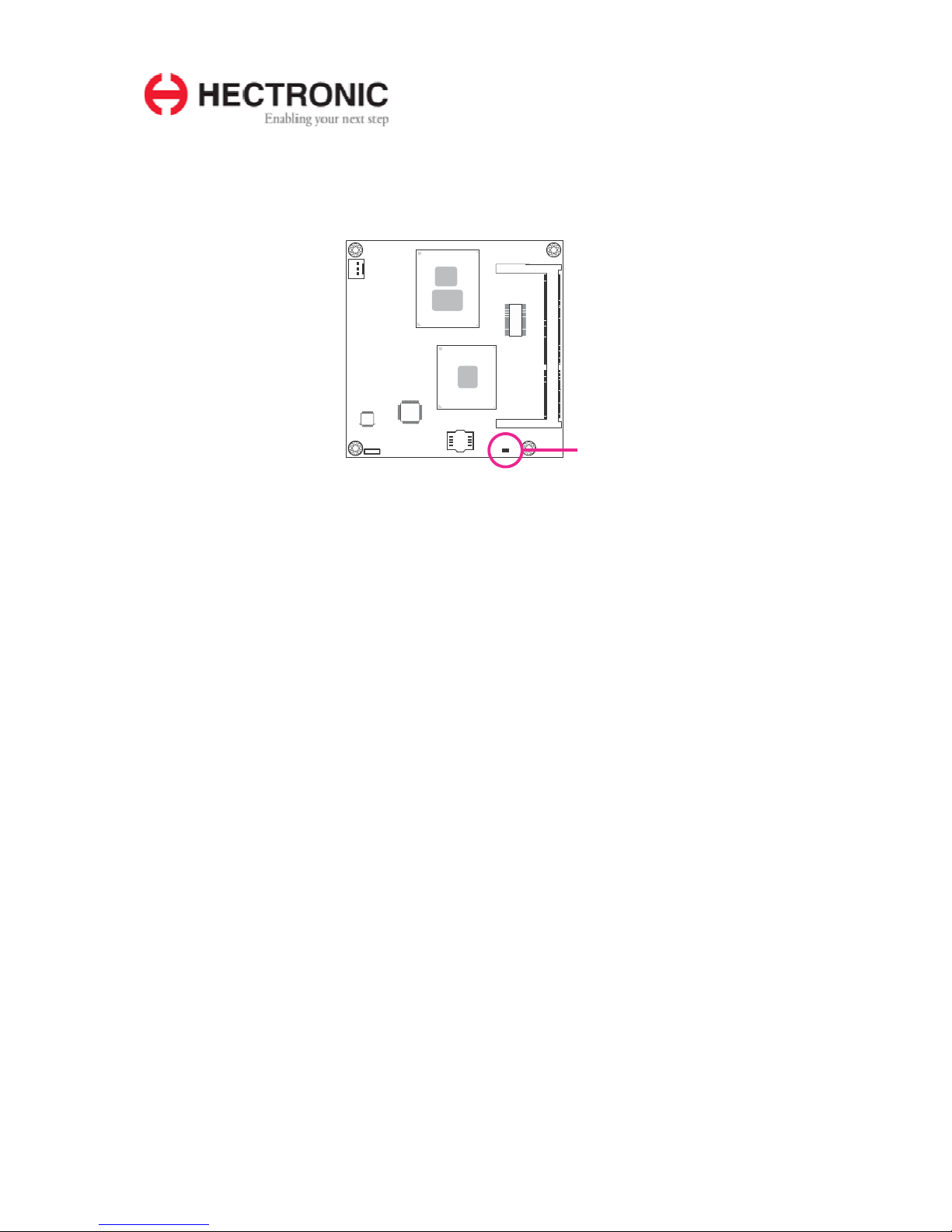
Standby
Power LED
Standby Power LED
This LED will light when the system is in the standby mode.
Table of contents
Other Hectronic Motherboard manuals

Popular Motherboard manuals by other brands

MSI
MSI 848P Neo2-V Series instruction manual

Intel
Intel BLKDH61WWB3 Technical product specification

Gigabyte
Gigabyte 6VX7-4X user manual

ASROCK
ASROCK G43TWINS-FULLHD Brochure & specs

Texas Instruments
Texas Instruments LMP91000EVM Operation & User’s Guide

Avalue Technology
Avalue Technology EMX-ADLP-B1 user manual


