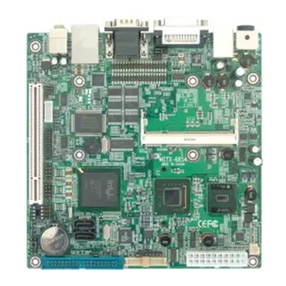
Norco MITX-6922 User manual

MITX-6922
Mini-ITX Motherboard
User’s Manual V3.0

Disclaimer
Except for the accessories attached to the product as specified herein,
what is contained in this user manual does not represent the commitments
of NORCO Company. NORCO Company reserves the right to revise this
User Manual, without prior notice, and will not be held liable for any direct,
indirect, intended or unintended losses and/or hidden dangers due to
installation or improper operation.
Before ordering products, please learn about the product performance
from the distributors to see if it is in line with your needs. NORCO is a
registered trademark of Shenzhen NORCO Intelligent Technology CO., LTD.
The ownership of other trademarks involved in this manual is owned by its
respective owners.
The contents of this manual are protected by copyright law. All rights
are strictly reserved. Any form of unauthorized reproduction including but
not limited to carbon copy, facsimile transmission and electronic copy or
email is prohibited.

Safety Instructions
1.Please read the product manual carefully before using this product.
2.Put all the unused or uninstalled boards or electronic components in a static dissipative
surface or static shielding bag.
3.Always ground yourself to remove any static discharge before touching the board, to place
your hands on grounding metal object for a while or wear an anti-static wrist strap at all times.
4.When taking or fetching the boards or cards, please wear antistatic gloves and have the
habit of holding the boards by its edges.
5.Make sure that your power supply is set to the correct voltage in your area. Incorrect voltage
may cause personal injuries and damage the system.
6.To prevent electronic shock hazard or any damage to the product, please ensure that all
power cables for the devices are unplugged when adding or removing any devices or
reconfiguring the system.
7.To prevent electrical shock hazard, disconnect the power cable from the electrical outlet
before relocating the system.
8.When adding or removing devices to or from the system, ensure that all the power cables for
the devices are unplugged in advance.
9.To prevent any unnecessary damage to the products due to frequent power on/off, please
wait at least 30 seconds to restart the unit after the shutdown.
10.If system goes wrong during the operation, do not try to fix it by yourself. Contact a qualified
service technician or your retailer.
11. This product is classified as Class A product, which may cause radio interference in our
living environment. On this occasion, users need to take measures to handle the interference.

Content
Chapter One Product Introduction........................................................................................................ 1
1.1 Introduction.................................................................................................................................1
1.2 Product Specification................................................................................................................ 1
Chapter Two Installation Specification................................................................................................. 4
2.1 Interfaces Location & Dimension............................................................................................ 4
2.2 Installation Steps....................................................................................................................... 4
2.3 Memory Installation...................................................................................................................5
2.4 Jumpers Setting.........................................................................................................................5
2.4.1 CMOS Clear/Hold Jumper Setting(JCC).............................................................. 5
2.4.2 Auto Boot upon Restore AC Power(JAT).............................................................. 7
2.4.3 ME Function Setting(JCM)..................................................................................... 7
2.4.4 COM2 Jumpers Setting(J5,J6,J8)................................................................... 8
2.5 Interface Specification.............................................................................................................. 8
2.5.1 SATA Port(SATA1-SATA4,HDD_POWER).........................................................9
2.5.2 Serial Port(COM1,COM2,COM3456)............................................................ 10
2.5.3 Display Port(VGA,DVI,LVDS)....................................................................... 12
2.5.4 LVDS Supply Voltage(LVDS_BKLT)................................................................... 15
2.5.5 USB Port(USB_12,USB_34,USB56_LAN1,USB78_LAN2)...................15
2.5.6 Keyboard and Mouse Interface(KBMS).............................................................. 16
2.5.7 Programmable Input and Output Port(JGPIO1、JGPIO2).............................. 17
2.5.8 Power Interface(ATX).............................................................................................19
2.5.9 Fan Interface(CPUFAN,SYSFAN).................................................................... 19
2.5.10 Audio Port(Audio,JAU,JAMP).......................................................................20
2.5.11 Front Panel Interface(JFP)..................................................................................21
2.5.12 Memory Slot(DIMM).............................................................................................23
2.5.13 MINI PCIe Port(MINI PCIe1,MINI PCIe2).....................................................23
Chapter Three BIOS Set up............................................................................................................... 25
AMI BIOS Refresh......................................................................................................................... 25
AMI BIOS Description................................................................................................................... 25

BIOS Set up....................................................................................................................................25
3.1 Main Menu...............................................................................................................................26
3.2 Advanced Menu......................................................................................................................27
3.2.1 APM Configuration......................................................................................................27
3.2.2 ACPI Settings............................................................................................................... 28
3.2.3 CPU Configuration......................................................................................................29
3.2.4 SATA Configuration.....................................................................................................30
3.2.5 AMT Configuration....................................................................................................... 31
3.2.6 USB Configuration...................................................................................................... 32
3.2.7 IT8783F Supper IO Configuration............................................................................ 33
3.2.8 IT8783F H/W Monitor.................................................................................................34
3.2.9 Serial Port Console Redirection................................................................................ 35
3.3 Chipset Menu..........................................................................................................................36
3.3.1 North Bridge.................................................................................................................36
3.3.2 South Bridge................................................................................................................ 38
3.4 Boot Menu................................................................................................................................ 39
3.5 Security Menu.........................................................................................................................40
3.6 Save & Exit Menu...................................................................................................................41
Appendix................................................................................................................................................. 42
Appendix 1:Watchdog Programming Guide........................................................................... 42
Appendix 2:Glossary.................................................................................................................. 44

Chapter
One
Product
Introdu
ction

MITX-6922 Mini-ITX Motherboard Based on Intel QM67/QM77 Chipset
1
Chapter One Product Introduction
1.1 Product Introduction
MITX-6922 is a Mini-ITX motherboard,with Intel QM67/QM77chipset,support Intel Socket
G2 Mobile Sandy/Ivy Bridge i7/i5/i3 processor,2x dual channel SO-DIMM memory slot,and
DDRⅢ/DDRIIIL 1066/1333/1600,memory up to16GB. 4xSATA ports,2xGigabit network port
(in which LAN1 support AMT function),provide VGA、DVI,LVDS,HDMI display port,and
6xserial ports,8xUSB 2.0 ports ,can be used for data communication. Support Line-out ,
Line-in,Mic-in,audio power amplifier and other functions,provide 2xMINI PCIe slot and on
board SIM card slot(can be used to support 3G modules).
1.2 Product Specification
Structural standard
●Standard Mini-ITX specification motherboard
Size
●170mm×170mm(L×W)
Processor
●Support Intel Socket G2 Mobile Sandy/Ivy Bridge i7/i5/i3 processor
Chipset
●Intel QM67/QM77
Display
●Display chip:Intel CPU Core i7/i5/i3 integrated
●VGA:1 x standard DB15 port,maximum resolution: 2048×1536@75Hz
●DVI:1 x standard DVI-D,maximum resolution: 1920×1200@60Hz
●LVDS:1 x standard dual channel 24bit LVDS,maximum resolution: 1920×1200@60Hz
●HDMI:1 x standard HDMI,maximum resolution: 1920×1200@60Hz
System memory
●2 x dual channel SO-DIMM memory slot,support DDRⅢⅢ/DDRIIIL 1066/1333/1600,memory

MITX-6922 Mini-ITX Motherboard Based on Intel QM67/QM77 Chipset
2
up to 8GB.
Storage
●4 x standard 7 Pin SATA port,in which SATA1,SATA2 support SATA 3.0。QM67 platform
support AMT7.0,QM77 platform support AMT8.0.
LAN Function
●Network controller:Adopt Intel 82579LM/82574L network chip
●2 x standard RJ45 port
●Support Wake On LAN(WOL)
●Rate:10/100/1000Mbps
In which USB56_LAN1(82579LM)support AMT function.
Audio port
●Adopt 662 7.1 HD audio control chip
●Audio port,blue for Line-in,green for Speak-out,red for Mic-in
●Built-in Audio expansion pin,one 2×5Pin pin,provide 1xLine-in,1xLine-out,1xMic-in
●Provide one 1×4Pin audio power amplifier interface,can support 2x 6W 8Ω loudspeakers
USB Port
●Provide 8x USB 2.0 ports
●Rear panel provide 4xstandard USB ports;On board two 2×5Pin USB pin,can be transferred
out 4x standard USB ports.
I/0 Functions
●Adopt ITE 8783F I/O chip
●6xserial port,COM1 is standard DB9 port,COM2 is 2×5 Pin,COM_3456 are 2×20 Pin,
needs to be connected by conversion cable。COM1-COM6 all support RS232,COM2 also
supports RS422/485 through jumping cap selection
●Provide one 2×4Pin keyboard and mouse interface
●Provide one 2×10Pin 5V programmable I / O interface, default 8xinput,8xoutput. It can also
be made into 16x inputs or 16x outputs.

MITX-6922 Mini-ITX Motherboard Based on Intel QM67/QM77 Chipset
3
Expansion Port
●2xMINI PCIe,MINI PCIe 1 support WiFi、3G module,MINI PCIe 2 support WiFi、3G module
and SSD card function
●On board SIM card slot,can support 3G network,need to work with MINI PCIe 3G module
Power Supply
●Standard ATX power supply
Watchdog
●Support hardware reset
BIOS
●8MB SPI BIOS
Environment
●Operating Temperature:0℃~60℃
●Storage Temperature:-40℃~85℃
●Operating Humidity:5%~95%,non condensing

Chapter
Two
Install
ation
Specifi
cation

MITX-6922 Mini-ITX Motherboard Based on Intel QM67/QM77 Chipset
4
Chapter Two Installation Specification
2.1 Interfaces Location & Dimension
Following picture illustrates the interfaces location and dimension of MITX-6922. Please
take care of some components during the installation. Improper installation may leads to
system failure.
Note: In case of any electrostatic damage caused to some components, please wear
anti-static gloves to install the motherboard.
MITX-6922 Interfaces Location & Dimension
2.2 Installation Steps
Please refer to following steps to assemble your computer:
1.Adjust all jumpers on board MITX-6922 according to the user manual;

MITX-6922 Mini-ITX Motherboard Based on Intel QM67/QM77 Chipset
5
2.Install Memory;
3.Install other expansion cards;
4.Connect all signal lines, cables, control panel circuit and power supply unit;
5.Start the computer and complete BIOS Settings
Key components of this motherboard are Integrated circuit and these components
could be easily damaged by electrostatic influence. So, before installing this unit, please
always keep the following precautions in mind:
1.Hold the board by edges and don’t touch any components, plugs or socket pins;
2.Wear anti-static gloves/wrist strap while touching the integrated circuit components, such as
CPU, RAM, etc;
3.Put those unused or uninstalled components in static shielding bags or trays;
4.Please first check the power switch is off before connecting the power plug.
2.3 Memory Installation
Board with 2xDDRⅢslot. Please pay attention to following two points when installing the
memory bank:
1.Align the notch of the DIMM memory bank with that of the socket. Insert the memory bank
into the socket and press the memory bank vertically and evenly on both sides until the
memory bank enters into the slot.
2.Select the memory bank that matches your motherboard.
2.4 Jumper Settings
Please refer to following instructions to do jumper settings before installing your hardware
devices.
Remark: How to identify the PIN1 of all jumpers and interfaces: Please observe the word
mark on the side of the plug socket, which will be a “1” or bold line or triangular symbol; And
please look at the back of PCB, each with a square shape will be the PIN 1; and all the jumpers’
PIN1 have a white arrow on the side.
2.4.1 CMOS Clear/Hold Jumper Setting(JCC)
CMOS is powered by the onboard button cell. Clear CMOS will lead to permanent
elimination of previous system settings(factory default).
Steps:(1)Turn off the computer, disconnect power supply;

MITX-6922 Mini-ITX Motherboard Based on Intel QM67/QM77 Chipset
6
(2)Use jumper cap to connect JCC pins 1 and 2 for 5-6 seconds, then restore to 2-3;
(3)Press "F9" -- "enter" to reload the optimal default value;
(4)Press F10 to save and exit the settings
JCC:
Setting
JCC
1-2
Clear CMOS content and restore all BIOS
2-3
Normal working status, default settings
Do not clear CMOS when the computer is power on, otherwise, it will cause damage
to the motherboard!
JCC

MITX-6922 Mini-ITX Motherboard Based on Intel QM67/QM77 Chipset
7
2.4.2 Hardware Switch for System Auto Boot upon Power on(JAT)
2.4.3 ME Function Setting(JCM)
JCM
JAT

MITX-6922 Mini-ITX Motherboard Based on Intel QM67/QM77 Chipset
8
JCM:
Setting
JCM
1-2
Clear ME setting
2-3
Normal working state, default setting
2.4.4 COM2 Jumper Setting(J5,J6,J8)
J5,J6,J8 jumper is to set COM2 transmission mode,COM2 support RS 232/RS 422/RS
485 transmission mode,you can choose settings according to your own needs,the default
transmission mode is RS 232.
2.5 Interfaces Description
Please read this manual carefully before installing any external connectors, in case
of any damage to the motherboard!
COM2 RS232(default)
COM2 RS422
COM2 RS485
J5
1-3 2-4
J5
3-5 4-6
J5
J6
1-3 2-4
J6
3-5 4-6
J6
3-5 4-6
J8
1-2
J8
3-4
J8
5-6
J5、J6
J8

MITX-6922 Mini-ITX Motherboard Based on Intel QM67/QM77 Chipset
9
2.5.1 SATA Port(SATA1-SATA4,HDD_POWER)
On board 4xSATA port,provide 1x5Pin HDD power supply voltage interface.
SATA:
Pin
Signal Name
1
GND
2
TX+
3
TX-
4
GND
5
RX-
6
RX+
7
GND
JSATAPWR:
Pin
Signal Name
1
+3.3V
2
GND
3
+5V
4
GND
5
+12V
SATA1-SATA4
HDD_POWER

MITX-6922 Mini-ITX Motherboard Based on Intel QM67/QM77 Chipset
10
2.5.2 Serial Port(COM1,COM2,COM3456)
Board with 6xserial port,COM1 is standard DB9 pin connector、COM2 is standard 2×5
Pin pin,the DB9 interface needs to be led out through the conversion cable;COM3-6 are 2×
20Pin pin,the equipment needs to be connected by conversion cable. Users can turn on or off
the serial port in the BIOS setting option, and can select its interrupt IRQ and I / O address.
COM1-COM6 all support RS232 transmission mode ,COM2 also support RS422/485
transmission mode. Users can select COM2 transmission mode by setting jumpers. Refer to
2.4.4 "COM2 jumper settings" in Chapter Two for detailed settings.
COM1:
Signal Name
Pin
Signal Name
DCD
1
2
DSR
SIN
3
4
RTS
SOUT
5
6
CTS
DTR
7
8
RI
GND
9
10
GND
COM2:
Signal Name
Pin
Signal Name
DCD
1
2
DSR
COM1
COM2
COM3456

MITX-6922 Mini-ITX Motherboard Based on Intel QM67/QM77 Chipset
11
SIN
3
4
RTS
SOUT
5
6
CTS
DTR
7
8
RI
GND
9
10
GND
When COM2 is set to RS232/RS422/RS485,the pins are defined as follows:
Pin
RS232
(default)
RS422
RS485
1
DCD
TX-
DATA-
2
DSR
NC
NC
3
RXD
TX+
DATA+
4
RTS
NC
NC
5
TXD
RX+
NC
6
CTS
NC
NC
7
DTR
RX-
NC
8
RI
NC
NC
9
GND
GND
GND
10
GND
GND
GND
COM_3456:
Signal Name
Pin
Signal Name
DCD3
1
2
DSR3
RXD3
3
4
RTS3
TXD3
5
6
CTS3
DTR3
7
8
RI3
GND
9
10
GND
DCD4
11
12
DSR4
RXD4
13
14
RTS4
TXD4
15
16
CTS4
DTR4
17
18
RI4
GND
19
20
GND
DCD5
21
22
DSR5

MITX-6922 Mini-ITX Motherboard Based on Intel QM67/QM77 Chipset
12
RXD5
23
24
RTS5
TXD5
25
26
CTS5
DTR5
27
28
RI5
GND
29
30
GND
DCD6
31
32
DSR3
RXD6
33
34
RTS6
TXD6
35
36
CTS6
DTR6
37
38
RI6
GND
39
40
GND
2.5.3 Display Port(VGA,DVI,LVDS)
VGA:
Pin
Signal Name
Pin
Signal Name
Pin
Signal Name
1
RED
6
GND
11
NC
2
GREEN
7
GND
12
SDA
3
BLUE
8
GND
13
HSYNC
4
NC
9
+5V
14
VSYNC
5
GND
10
GND
15
DDCCLK
VGA、DVI
LVDS
HDMI

MITX-6922 Mini-ITX Motherboard Based on Intel QM67/QM77 Chipset
13
DVI(18Bit DVI cable is recommended):
Signal Name
Pin
Signal Name
TDC2#
1
2
TDC2
GND
3
4
NC
NC
5
6
SC-DDC
SD-DDC
7
8
NC
TDC1#
9
10
TDC1
GND
11
12
NC
NC
13
14
VCC
GND
15
16
HP-DETECT
TDC0#
17
18
TDC0
GND
19
20
NC
NC
21
22
GND
TLC
23
24
TLC#
GND
25
26
GND
NC
27
28
NC
LVDS:
VDD_PANEL
1
2
VDD_PANEL
VDD_PANEL
3
4
NC
GND
5
6
GND
LVDSA_DATA0#
7
8
LVDSA_DATA0
LVDSA_DATA1#
9
10
LVDSA_DATA1
LVDSA_DATA2#
11
12
LVDSA_DATA2
GND
13
14
GND
LVDSA_CLK#
15
16
LVDSA_CLK
LVDSA_DATA3#
17
18
LVDSA_DATA3
LVDSB_DATA0#
19
20
LVDSB_DATA0
LVDSB_DATA1#
21
22
LVDSB_DATA1
LVDSB_DATA2#
23
24
LVDSB_DATA2
GND
25
26
GND
LVDSB_CLK#
27
28
LVDSB_CLK
LVDSB_DATA3#
29
30
LVDSB_DATA3
Other manuals for MITX-6922
1
Table of contents
Other Norco Motherboard manuals

Norco
Norco BPC-7934 User manual

Norco
Norco EMB-3682 User manual

Norco
Norco MITX-6854 User manual

Norco
Norco MITX-6922 User manual

Norco
Norco MITX-6891 User manual

Norco
Norco MITX-6946 User manual

Norco
Norco MITX-6934 User manual

Norco
Norco EMB-7536 User manual

Norco
Norco BPC-7971 User manual

Norco
Norco ATX-6991 User manual

Norco
Norco MITX-6892 User manual

Norco
Norco MATX-6959 User manual

Norco
Norco MITX-6110 User manual

Norco
Norco SOMB-073 User manual

Norco
Norco EMB-7541 User manual

Norco
Norco MITX-6930 User manual

Norco
Norco EMB-2510 User manual

Norco
Norco SOM-6670 User manual

Norco
Norco EMB-4850 User manual

Norco
Norco EMB-3503 User manual