Heden Carat CT-100 FF User manual

!
1!
!
!
HEDÉN®
CARAT
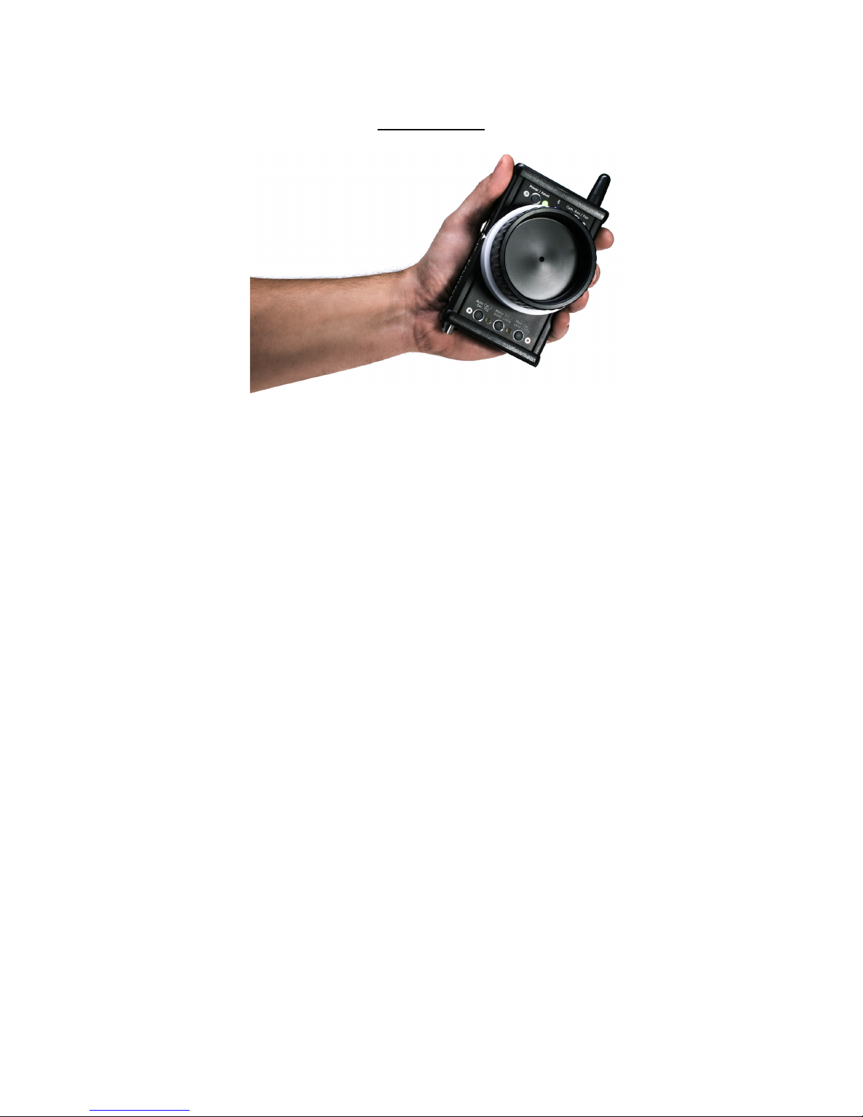
Hedén Remote Control Unit
Hand Unit (Tx) and Reciever unit (Rx)
Operation Manual
Version 0.9 Beta
Copyright © 2014 by Hedén Engineering Co.
Hedén Engineering AB
SWEDEN
www.heden-engineering.com
email: sales@heden-engineering.com

!
2!
Table Of Contents
Introduction…………………………………………………………………………………………………...3
Hand Unit (Tx)………………………………………………………………………………………………...4
Hand Unit buttons-…………………………………………………………………………………………...5
Hand Unit LED´s….………………………………………………………………………………………….6
Hand Unit overview...…………………………………………………………………………………….….7
Receiver (Rx) …………………………………………………………………………………………….…..8
Receiver (Rx) buttons..……………….. ……………………………………………………………..……..8
Receiver (Rx) LED´s….…………………………………………………………………………….……….8
Receiver (Rx) overview…….…………………………………………………………………………….….9
Installation …………………………………………………………….…………………………………….10
Troubleshooting………………….…………………………………………………………………….…...11
Specifications…………………………………………………………………………………………….…12
!
!!!!!!!!!
!
!
!
!
!
!
!
!
!
!!!!!!!!!!!!!!!!!!!!!!!!!!!!!!!!!!!!!!!!!!!!!!!!!!!!!!!!!!!!!!

!
3!
!!!Introduction
Congratulationsy you are now a proud owner of a high quality product from Hedén Engineering Co.
The Hedén Carat CT-100 FF-system is delivered with following parts:
1 x Hand Unit (Tx)
1 x Receiver (Rx)
1 x Digital motor (M21VE,M21VE-L or M26VE) with gear module 0.8
1 x 9V (8.4V) Li-On battery for hand unit
1 x Power cable DTap 0,5m
1 x Motor cable for Digital Motor, 0,5m
2 x Quick change marking disc
1 x Hedén carrying case
With this system you can wirelessly and precisely control focus or iris on most professional camera lenses. We hope you will
enjoy using this system.
Please feel free to contact us if you have any questions or comments regarding our product.
A Hedén Lens Control system consists of a hand unit / transmitter(Tx), a receiver / amplifier (Rx), a Hedén motor M26VE,
M21VE or M21VE-L and appropiate cables, forming a high precision null-seeking closed loop servo system.
Important! If another lens motor model will be used this has to bet set correctly in the Hedén PC GUI before starting up the
system. If this is not done the system will not work properly and damage to the lens may occur.
The Bluetooth wireless protocol enables you to wirelessly control the motor via the receiver / amplfier unit.
The Rx unit is normally powered from an external battery or from the camera power output connector
The binding of the transmitter and receiver is quick and easy procedure, ensuring interference free operating. The outdoor
range in free sight is up to 1000 meters. Indoor range is approx 30 –60 meters.
For easy and quick setup the system is delivered factory Bluetooth paired.
The system can also control Fujinon Cabrio internal FIZ motors via the Aux port (marked AM on Rx unit). Serial cable #CT-500
or #CT-501 is needed for this.
Please read this manual carefully before starting using the system. There is a quick guide printed on the backside of the hand
unit.
!
!
!
!
!
!
!
!
!
!
!
!
!
!
!
!
!
4!
!
Hand unit (Tx)
1. Battery
Type 9V block battery. We strongly recommend rechargeable Li-Ion of at least 600mah
Battery change:
Battery is removed by pulling the bottom gable cover straight out, All personilized settings will be stored during a battery
change
LED (B) (Fig1) shows battery charge status as follows:
Solid green: battery status more than 20 %
Solid Red: battery status less than 20 %
Flashing red: battery status less than 10 %. Replace battery immediately
Intelligent power sleep modes:
The hand unit goes into sleep mode after 180 seconds of inactivity. LED B will flash green (0,5 Hz). Hand unit will
start up instanly when activity is determined as for example when control knob is turned or a button is pressed.
After 10 minutes of inactivity the Hand Unit is powered off. To start it up press power button (A)
When battery voltage drops below 7.0 Volt the hand unit will go into battery safe mode. In safe mode the power button is
not operative.
2. USB
The hand unit has a mini-usb connector that is used for the Heden PC GUI.
3. Neckstrap.
The neckstrap can be safely attached to the 1/4” SS thread at the bottom of the hand unit.!
!
!
4. Control knob
The knob is extremely smooth and gives the operator superior precise control of the lens motor. Total travel of the knob is
270 degrees.

!
5!
Setting the drag of the knob:
The drag of the knob can be adjusted. This done by connecting the HLC via the mini-USB port to a PC that runs the Heden
GUI. Instructions how to adjust the drag is found in the Heden PC GUI under potentiometer calibration.
.
5. Quick change Focus / Iris marking disc
The marking disc could be marked with a pen so it matches up with the lens you are using.
The marking disc can easily be removed by pulling it straight out of the knob. To insert a new marking disc just rotate the
disc until it locks into place and push it in.
You will here a click sound when it is in place.
Spare marking discs are sold separately
6. Power / Reset button (A)
Quick press power button (A) to turn on/off the Hand Unit. LED (B) is solid green showing that unit is turned on.To
maximize battery and to protect deep discharge of the battery the system has several power saving modes.
Using the Heden PC GUI you can change the standard values of the sleep delay timer and the shutdown delay timer.
After 180 seconds of inactivity the Hand unit goes into power save mode. The Power LED (B) will flash green slowly. To
wake it up turn the knob or press a button.
After 10 minutes of inactivity the Hand unit will turn off. Start it up by quick press the power button (A)
The Hand Unit goes automaticly into battery safe mode when battery voltage is drops under 7.0 V. LED (B) will flash red
indicating that you need to replace the battery
Battery status LED (B): Solid green: battery level more than 20 %.
Solid red: battery level less than 20 %. Flashing red: battery level less than 10 %.
8. The auto lens calibration button and manual calibration button. (F & J)
Auto calibration of lens; depress button Fand release after approx 2 sec LED (G) & (I) starts to flash (4Hz) orange. The
motor, if attached to the lens, will now start an automatic lens calibration procedure by detecting the mechanical end stops of
the lens.
The auto calibration feature has automatic lens torque detection. This means that an advanced algorithm is calculating
optimal motor torque that is needed to calibrate the lens in the best possible way, saving both lens and lens motor from
excsessive wear
When the calibration procedure is finished LED (G) will turn solid green.
If calibration fails because of super stiff lens you can use manual setup. Manual setup is always done with 100 % motor
Torque and the auto torque detection function is disabled
Manual setup: Press button (J) for approx 2 secs until LED (I) turns orange. Carefully turn the knob to its halfway position
LED (I) will start flashing amber 4Hz. Here you will find a small bit of deadband ( motor is not moving in any
direction when knob is turned)
Now you can speed control the motor in desired direction to find the mechanical ends stops of the lens barrel. Please be
carefull when you do this, it will take some practice to be good at it. When an end stop is reached press the (J) button
Turn knob opposite to move motor into second position and then press knob (J) again. Now LED (G) will be solid green
If the setup is made correcty. This manual calibration procedure can also be used on infinate rotating lenses where there is
no physical end.

!
6!
9. Lens limits button (J) (lens mapping)
This function allows the operator to mapp out a part of the total lens travel to correspond to the full travel of the knob.
Quick press button (J) to set the first lens limit, LED (I) flashes at 4Hz turn the knob and go to the second desired lens limit
and quick press button (J) again, now LED (I) now flashes at 2Hz indicating that a lens limit now is set and ready to use.
Now the full travel of the knob will correspond to the digital limits just set. To release the limits press (J) button again.
LED (I) goes dark.
10. Knob limit button (F) (knob mapping)
This function allows the operator to map out a part of the total travel of the knob
Quick press button (H) to set the first knob limit LED (G) flashes at 4Hz then go to you next desired knob limit and press
button (H) again. LED (G) flashes at 2Hz indicating that a knob limit has been set Now your motor
movement will correspond to the limits of the knob just set. If you override the limits the motor will not move. To release limits
press button (H) again.
11. Motor direction button (H)
The motor direction button (H) can change the direction of the motor travel. Depress for 2 seconds and release to change
the direction.
10. Camera Run/Stop button / Bluetooth pairing button (E)
Quick press camera Run button (E) to activate camera Run function. LED (D) flashes at 1Hz red. Press again to stop camera
Run. LED (D) goes dark.
Bluetooth pairing: power up hand unit and Receiver unit . Depress pairing button on both hand unit and receiver unit for 2
seconds or more and release When the pairing process is successfully done the blue LEDs stops flashing and turn solid
blue.
11. Power LED (B)
Solid green: battery status more than 20 %
Solid Red: batterystatus less than 20 %
Flashing red: battery status less than 10 %. Exchange battery.
The hand unit goes into automatic into sleep mode after 30 seconds of inactivity. LED (B) will flash green (0,5 Hz). Hand unit
willstart up instanly when activity is determined as for example when control knob is moved or a button is pressed
12. Camera run LED (D)
This LED (D) has two functions:
1.Flashing 1HZ red when camera run is activated.
2.Indicating if motor is running. LED is flashing green when motor is running giving you feedback that the motor works ok
13. Bluetooth LED
When LED (C) is flashing it indicates no Bluetooth connection to receiver. Receiver is out of range or units are not paired
When LED (C) lights solid blue it is Bluetooth connected / Paired to receiver unit
14. Auto setup LED & Manual setup LED (G & J)
LED (G and J) flashes amber (0,5Hz) indicating that an autosetup could be performed.
When auto setup is initiated LED (G) flashes with 4Hz. When autosetup is finsihed LED (G) turns
solid green. If setup is not completed correctly LED (G & J ) flashes red.
LED (J) turns solid orange indicating that a manual setup has been initiated. Flashing (4Hz) motor is moving.
LED (G) turns solid green, manual calibration is finis
!
7!
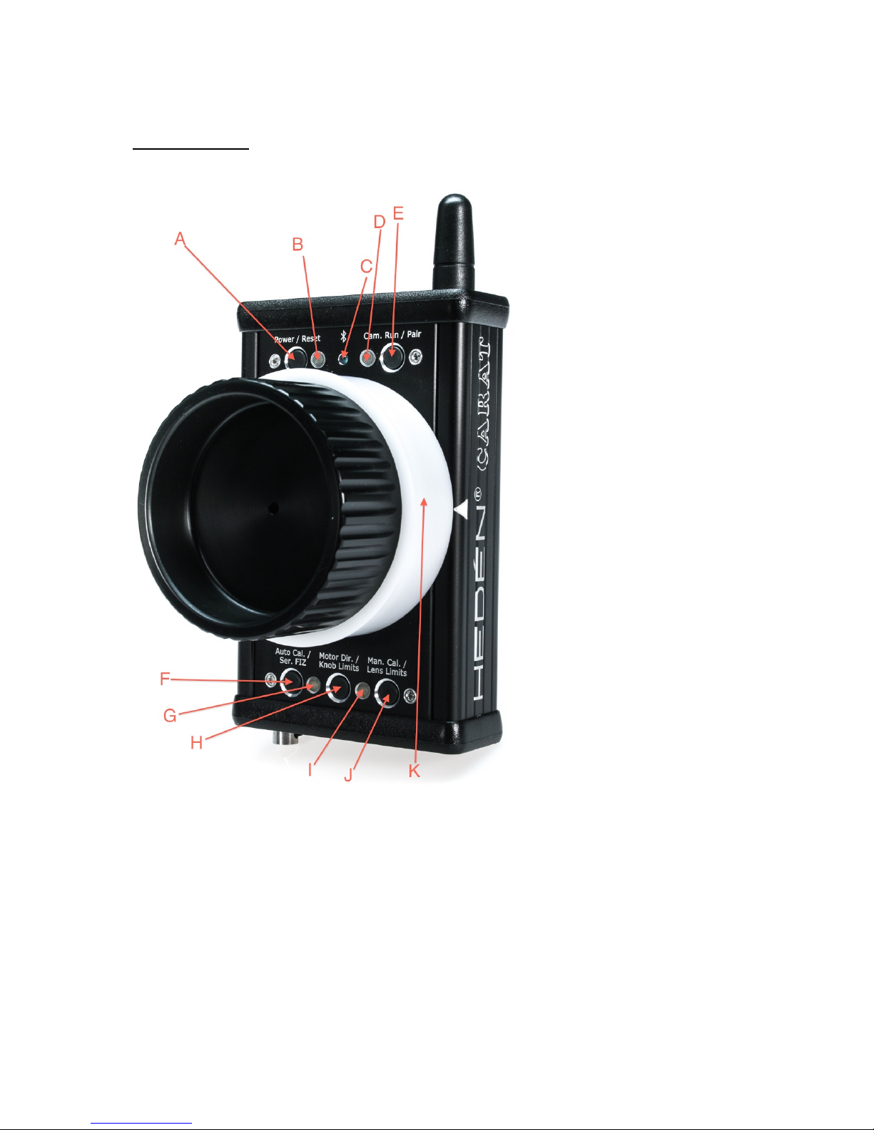
Hand unit Fig 1
A. Power on/off button / Reset button
B. Power on LED and battery status LED
C. Bluetooth LED
D. Camera run LED and motor feedback LED
E. Camera Run button and Bluetooth Pairing button
F. Auto lens calibration button & serial FIZ button
G. Auto lens calibration LED
H. Motor direction button and knob limits button
I. Manual lens calibration LED
J. Manual lens calibration and lens limits button
K. Quick change marking ring

!
8!
Receiver (Rx)
Receiver can be mounted using Dual-Lock, velcro or by using the ¼” thread and the backside.
You can also use the optional V-lock mounting plate.
Don´t drill holes in the receiver box as it easily could damage the electronics inside.
Bluetooth Pairing Button (6)
Press button (6) for at least 2 seconds to start up the Bluetooth pairing process. LED (5) will start fast
Flashing looking for the hand unit. If paring is succesfull the LED (5) will turn solid blue.
When pairing process is ongoing the handunit and transmitter unit should be at least 1 meter from each other.
If they are to close pairing process may fail.
Power LED (4)
LED (4) Indicates receiver unit power status
Solid green = power ok
Bluetooth LED (5)
LED (5) Solid blue: connected to hand unit
Flashing blue: not connected to hand unit, out of range or not Bluetooth paired
!
!
!
!
!
!
!

!
9!
1. Digital motor, Hedén M21VE or M26VE, Lemo 7-pin, EGG.1B.307.CYM
2. Aux motor/ serial , Fujinon Cabrio servo motors Lemo 5-pin, EGG.1B.305.CYM
3. Power in. Lemo 2-pin, EGG.0B.302.CYM (10 –30 VDC)
4. Power LED (not available on Carat Rx)
5. Bluetooth LED
6. Bluetooth pairing button
7. Camera Run Lemo 4-pin ERA.0S.304.CLL
!
!
!
!
!
!
!
!
!
!
!
!
!
!
!
!
!

!
10!
Installation
1. Hand unit with receiver (Rx) , Bluetooth connection mode.
Hand unit (Tx) and receiver (Rx) connected in wireless mode
Engage motor to lens using appropiate gear module. Make sure that the gears are not to tight.
Connect the Dtap power cable to the receiver unit . Connect camera run cable to receiver unit if neccessary
Switch on hand unit. Be sure that the Li-Ion battery is fully charged.
When Bluetooth LEDs on hand unit and on receiver turns solid blue they are connected.
Now connect motor cable between receiver unit and motor.
The LEDs (G and I) for calibration will start to flash oange (0,5Hz) r indicating that the unit wants to have a command before
starting to operate. Depress button F or J on hand unit for at least 2 seconds to activate auto or manual calibration
!
All settings are memorized as long as the motorcable is connected. If motor cable is removed from receiver unit when power is
on, a new lens calibration is needed.
CAUTION!: When engaging the motor to the lens beware your fingers as the motor can be very powerful.
!
!
!
!
!
!
!
!
!
!
!
!
!

!
11!
Troubleshooting
1. The hand unit will not turn on. Check your battery if the voltage is below 5V it will not start up the hand unit.
2. Motor is not running smooth. Check that the motor the system was delivered with is used. If not please contact us.
3. LED (G & I) flashed red. Motor, Encoder or lens calibration failure. Recycle power on receiver unit.
4. How can I activate the FIZ button (F)? The button can be used when a Fujinon Cabrio lens is connected to the Rx. You can
smart jump between the FIZ axis. LED (G) will shift color depending of which axis you are operating. The control knob will
memorize its last position and lens motor will not move until you come back to the exact position you left it in.
My notes:
!
12!
Specifications
Hand Unit
Dimensions: 128mm x 78mm x 27mm
Weight: 450 grams
Battery 9V style (6.5V-30V)
Power consumption: approx 70mA
Wireless system: Bluetooth Long Range Adaptive Radio, 2.4 GHz
Radio type approved in US/Canada, Europe & Japan
CE & FCC
Antenna: External robust, unbreakable
Mini-USB interface for Heden PC GUI
¼” thread with neckstrap hole
Receiver unit:
Dimensions: 70mm x 60mm x 30mm
Weight: 135g
Power input 10 –30V
Wireless system: Bluetooth Long Range Adaptive Radio, 2.4 GHz
Antenna: External robust, unbreakable
Mini-USB interface for Heden PC GUI
¼” thread on backside
Connectors:
Lemo 7-pin 1B for digital motor
Lemo 5-pin 1B for Aux motor
Lemo 4-pin ERA.0S.304.CLL for camera run
The Hedén Carat system is RoHS compliant.

!
13!
Table of contents


