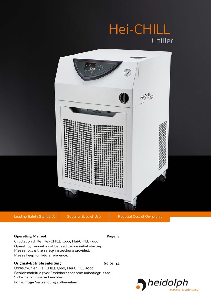
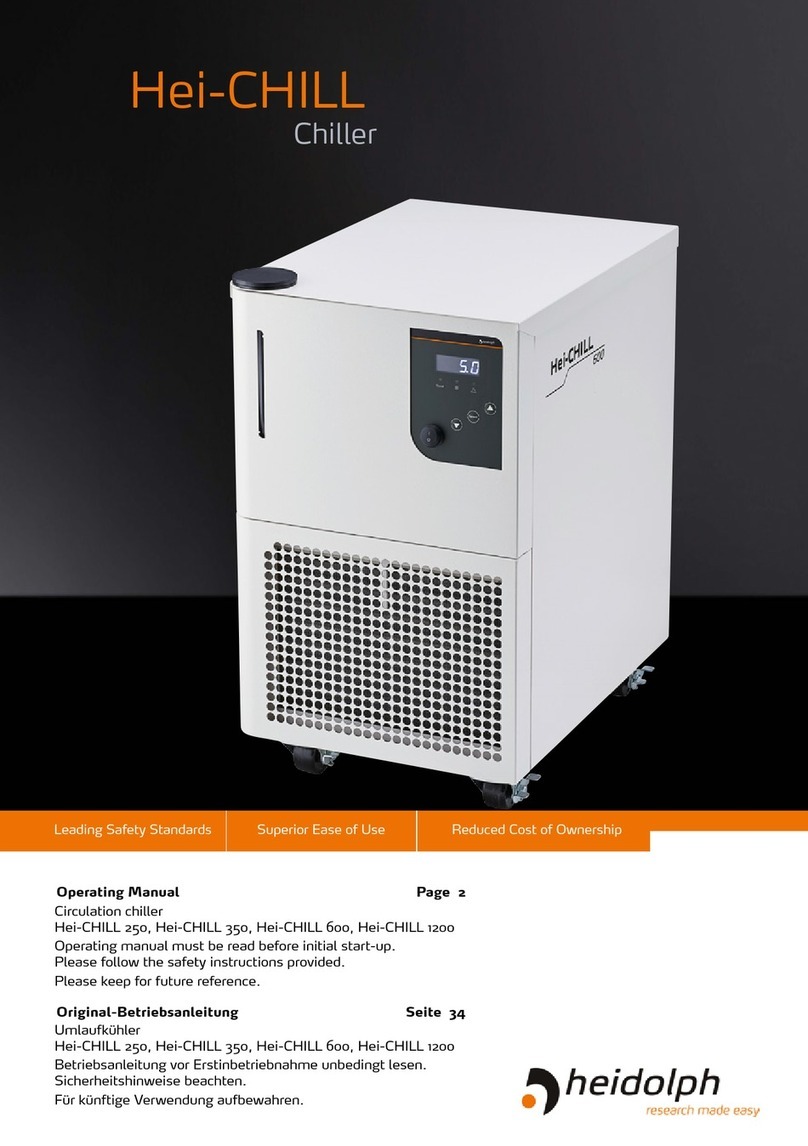
Heidolph RotaChill Large User manual

Leading Safety Standards Superior Ease of Use Reduced Cost of Ownership
Chiller RotaChill Large
Operating manual must be read before initial start-up.
Please follow the safety instructions provided.
Please keep for future reference.
Umlaufkühler RotaChill Large
Betriebsanleitung vor Erstinbetriebnahme unbedingt lesen.
Sicherheitshinweise beachten.
Für künftige Verwendung aufbewahren.
RotaChill Large
Chiller
Operating Manual Page 2
Original-Betriebsanleitung Seite 34

Contents
Inhaltsverzeichnis
About this document 4
Version and variants ...........................................................................................4
About this manual ..............................................................................................4
Terms and signs used..........................................................................................5
Safety Instructions 6
General safety instructions...................................................................................6
EC Declaration of Conformity.........................................................................6
Intended use...............................................................................................6
Installation / Electrical safety .......................................................................6
Personnel qualication..................................................................................7
Operating company’s obligations...........................................................................7
Installation site ...........................................................................................7
Changes to the unit .....................................................................................7
Safety for the personnel ...............................................................................8
Safety during use ...............................................................................................8
Disposal ............................................................................................................8
Device Description 9
Device overview .................................................................................................9
RotaChill Large overall view...........................................................................9
RotaChill Large control panel.........................................................................9
Start Up 10
Set up.............................................................................................................10
Power cord ...............................................................................................10
Main switch...............................................................................................11
Process Coolant.........................................................................................11
Filling the Reservoir ...................................................................................12
Switch unit on and off ................................................................................12
Starting process uid ow..................................................................................13
Operation 14
Normal operation..............................................................................................14
Selecting the Temperature Unit (°C or °F).....................................................14
Displaying and Adjusting the Set Point.........................................................14
Setting Operational Parameters ...................................................................15
Operational Parameters ..............................................................................15
Enabling/Disabling the Local Lockout (LLO) .................................................17
Operating Manual

Contents
Cleaning and Maintenance 18
Cleaning..........................................................................................................18
Maintenance ....................................................................................................18
Troubleshooting 20
Possible errors and how to resolve ......................................................................20
Error codes ...............................................................................................20
Other problems .........................................................................................21
Assembly 23
Electrical connections........................................................................................23
Set up chiller ...................................................................................................24
Hoses and connectors ................................................................................24
Closed System or Cooling Coil Setup ............................................................25
Disassembly and Storage 26
Dismantling, transportation and storage ..............................................................26
Dismantling ..............................................................................................26
Transportation and storage .........................................................................26
Accessories and Spare Parts 27
Scope of delivery..............................................................................................27
Attachments 28
Technical data ..................................................................................................28
Performance range.....................................................................................29
Contact / Technical Service ................................................................................30
Warranty.........................................................................................................31
Conrmation of condition of unit.........................................................................32

About this Document
4
About this document
Version and variants
Version
This manual describes the function, operation and maintenance of the compact chiller
RotaChill Large.
Version Alteration date
0.1 07/2015
Variants
The units are available in different con gurations. Certain features and functions apply to
speci c con gurations only. The varieties are documented in this manual.
About this manual
This operating manual is a component of the device described here.
➜Please read this manual carefully and obey all safety and warning
notices.
➜Ensure that every operator reads this manual.
➜Ensure that this manual is accessible for every operator.
➜Pass on the operating manual to the subsequent owner.
For the current version of this operating manual in pdf format, please
go to:
http://www.heidolph-instruments.com/Support/Operation Manuals/
Rotary Evaporators/Chillers/RotaChill Large
In addition please observe the regional regulations.

5
About this Document
Terms and signs used
In this manual you will nd standardized terms and signs to warn you of possible dangers
or give important hints. Please take special notice to these signs to avoid personal injury
or damage to the appliance.
The following terms and type of signs (basic drawing elements) are used:
Symbol Additional term / Description
Warning signs The yellow triangle indicates hazardous situations. It is used in
combination with the following terms:
DANGER:
Indicates a hazardous situation which, if not avoided, will result in
irreversible injury or death.
WARNING:
Indicates a hazardous situation which, if not avoided, could result in
serious injury or material damage.
CAUTION:
Indicates a hazardous situation which, if not avoided, may result in a
minor injury or material damage.
Prohibitory
signs
Not to do:
The red circle indicates a situation that should be avoided under all
circumstances to avoid injury or damage.
Mandatory
signs
To do:
The blue circle indicates important information. Please obey to avoid
property damage.
Other signs used
Symbol Description
➜Handling instruction, action required
✓Result of action
▪
▪
▪
List of information
a.
b.
c.
List of variants

Safety Instructions
6
Safety Instructions
General safety instructions
EC Declaration of Conformity
This device complies with the following EC-Directives*:
▪2006/42/EC Machinery Directive
▪2006/95/EC Low-Voltage Directive
▪2004/108/EC Electromagnetic Compatibility Directive
*Also see attachment “EC Declaration of Conformity”.
The device has been constructed according to state-of-the-art technology and recog-
nized safety regulations. However, risks may still arise during installation, operation and
maintenance.
➜Please ensure the operating manual is available at all times.
The device may only be used under the following circumstances:
➜Only operate the device, if it is in full working order.
➜Ensure all operators of the device possess the necessary safety and risk awareness.
➜Operate the device according to the instructions stipulated in this manual only.
➜If there is something you do not understand, or certain information is missing, ask
your manager or contact the manufacturer.
➜Do not do anything on the device without authorization.
➜Only use the device according to its intended use.
Intended use
The device is intended for use by trained and authorized personnel only.
The device is suitable for the following
use:
▪economical cooling as alternative to tap
water systems
The operation for the device is suitable
in one of the following locations:
▪in any research application
Improper use
Any use which deviates from the device’s intended use is considered to be improper. The
manufacturer does not accept liability for any damages resulting from non-permitted
uses. The risk is carried by the operator alone.
Installation / Electrical safety
▪The device may only be connected when the mains voltage corresponds to the infor-
mation on the type plate of the unit.
▪The mains connection must be accessible at all times.
▪Repairs may only be performed by a qualied electrician.
▪Never operate the unit with a damaged power cord.
▪Always turn the unit OFF and disconnect mains power before performing any
maintenance or service.

7
Safety Instructions
Personnel qualication
▪The device may only be operated by qualied persons.
▪The device may only be operated by individuals who have been instructed in its
proper use by qualied persons.
▪The device may only be operated and maintained by persons who are of legal age.
▪Other personnel may only work with the unit under continuous supervision of an
experienced qualied operator.
▪This manual must be read and understood by all persons working with the device.
▪The personnel must have received special safety instructions in order to guarantee
responsible and safe work procedures.
Operating company’s obligations
Installation site
▪The device must be positioned in a suitable location.
▪The device must be installed sufciently stable on a strong and level surface.
▪All screw connections must be securely tightened.
▪The device should be located as close to possible to the process requiring cooling.
▪The device should not be installed closer than 1.4 meters (4 feet) to a heat-gener-
ating source, such as heating pipes, boilers, etc.
▪If possible, the device should be located near a suitable drain to prevent ooding in
the event of leaks.
▪Do not place the device where corrosive fumes, excessive moisture, excessive dust,
or high room temperatures are present.
▪The device may only be operated in enclosed spaces and under the following environ-
mental conditions:
Ambient temperature 80 % relative humidity, no condensation
5 - 35 °C
▪Adequate clearance should be allowed on the front, sides, top, and rear of the device
for access to connections and components.
▪The front and side vents of the device must be a minimum of 21 cm (8 inches) away
from walls or vertical surfaces so air ow is not restricted.
Changes to the unit
▪No unauthorized changes may be made to the unit.
▪No parts may be used which have not been approved by the manufacturer.
▪Unauthorized changes result in the EC Declaration of Conformity loosing its validity,
and the appliance may no longer be operated.
▪The manufacturer is not liable for any damage, danger or injuries that result from
unauthorized changes or from operating the unit other than described in this manual.

Safety Instructions
8
Safety for the personnel
➜Ensure that only qualied personnel operate the device.
➜Observe the following regulations:
- Laboratory guidelines
- Accident prevention regulation
- Ordinance on Hazardous Substances
- Other generally accepted rules of safety engineering and occupational health
- Local regulations
Safety during use
➜Wear the appropriate protective clothing when working on the device (clothing,
protective glasses and if necessary, safety gloves).
➜Do not use the device in potentially explosive areas. The device is not protected
against explosion. There is no explosion or ATEX protection available.
➜Do not operate or assemble devices in the vicinity which are emission or radiation
sources (electromagnetic waves) for the frequency range (3×10¹¹ Hz to 3×10¹⁵ Hz).
➜Avoid putting pressure on the display when you do not operate the device.
➜Eliminate errors immediately.
➜Do not use abrasive material to clean the glass surfaces. Only wipe with damp cloths.
➜Always switch the device off after use.
Disposal
➜Check the device components for hazardous substances and solvents.
➜Clean all components before disposal.
➜Dispose of the device according to the valid national legal regulations.
➜Dispose of the packaging material in accordance to the valid national legal
regulations.

Device Description
9
Device Description
Device overview
RotaChill Large overall view
Reservoir cap
Fluid level
indicator
Air Filter
Compartment
Control panel
RotaChill Large control panel
Heating LED
Set button:
switch between
F and °C
Up/Down buttons:
adjust cooling
temperature
On/Off button
Cooling LED
Display

Start Up
10
Start Up
Set up
Power cord
Warning:
Electrical shock!
As long as the unit is not completely set up, electrical voltage is a
potential risk to your health.
Do not plug the Chiller into the electrical outlet until the unit is ready
for Start up.
Connect power cord
The power cord comes with a three-pole
plug and a recess on the bottom side.
Power cordUnit plug
The socket is located on the back side of
the unit.
➜Connect plug to the socket with the
recess facing left.
➜Push plug up against socket until
securely attached.
➜Connect plug to power socket.
Unit socket
Disconnect power cord
➜Disconnect plug from power socket rst.
➜Then disconnect plug from socket on unit.

Start Up
11
Main switch
The main switch is located on the rear
side of the unit.
With the main switch the unit is entirely
switched on to the electric system and off.
Connect to power supply
➜Press On/Off switch at the upper side.
✓The unit is now connected.
Disconnect from power supply
➜Press the On/Off switch at the lower side.
✓The unit is now disconnected.
On/Off switch: On On/Off switch: Off
Process Coolant
The Chiller is designed to accommodate a variety of coolant uids (water, glycol mixtures, etc).
▪For most applications above 20°C (68°F), distilled water is satisfactory.
▪Ethylene glycol (laboratory grade) and distilled water in a 50/50 mixture is satis-
factory from +20° to -15°C (68° to 5°F).
Caution:
Possible damage to the cooling system.
At low temperatures the uids might freeze and damage the chiller.
For operation at or below 20°C (68°F), the Chiller must be protected
with an antifreeze solution.
Warning:
Hazardous to health and environment!
Caustic, corrosive, or ammable uids might endanger your health.
Do not use the following uids:
▪Automotive antifreeze with additives**
▪Hard tap water**
▪Deionized water with a speci c resistance > 1 meg ohm
▪Any ammable uids
▪Concentrations of acids or bases
▪Solutions with halides: chlorides, uorides, bromides, iodides or
sulfur
▪Bleach (Sodium Hypochlorite)
▪Solutions with chromates or chromium salts
▪Glycerin
▪Syltherm uids
Only use uids that will satisfy safety, health, and equipment
compatibility requirements.
** At temperatures above 40°C, additives or mineral deposits can adhere to the heater. If deposits are allowed to build
up, the heater may overheat and fail. Higher temperatures and higher concentrations of additives can hasten deposit
build up.

Start Up
12
Select a uid that is compatible with the Chiller’s wetted parts
(brass, copper, stainless steel, EPDM rubber, Alcryn, nylon, PVC, and
polyethylene).
➜To prevent algae growth in the system, shield tubing from light.
Insulation around the tubing will suf ce.
➜Use an algaecide in the cooling water to minimize algae growth.
Caution:
Possible damage to the unit
Chlorine might damage metall surfces.
Do not use chlorine bleach as an algaecide.
Filling the Reservoir
The reservoir holds approximatly 3 liters.
You will nd the reservoir inlet at the top
of the unit.
➜Unscrew the reservoir cap.
➜Carefully ll the reservoir with uid.
➜Leave the cap off and add additional
uid as instructed under section
“Starting Process Fluid Flow”, below.
Reservoir cap
Switch unit on and off
Caution:
Possible damage to the unit!
If proper uid level is not maintained, the cooling system might get
damaged or the unit might not operate.
Always ensure suf cient uid level, before switching on the device
Switch unit on
➜Press the On/Off button at the control
panel.
✓The unit is switched on.
Switch unit off
➜Press the On/Off button at the control
panel again.
✓The unit powers off.
On/Off button

Start Up
13
Starting process fl uid fl ow
✓The reservoir is lled with cooling uid up to the mark “Full”.
✓The power cord is connected.
➜Place the Circuit Breaker/Power Switch on the rear of the instrument enclosure in the
“On” position.
✓Three decimal points will appear on the Temperature display.
➜Press the Power Button on the front panel.
✓The uid level indicator illuminates blue.
✓The set point temperature will appear brie y on the Temperature display.
✓After a few seconds, it will be replaced by the actual uid temperature.
➜Check for leaks.
✓The pump will turn on and uid will begin circulating through the system.
✓Ninety (90) seconds after power up, the compressor will begin operating.
✓With the pump running, the reservoir’s uid level will drop as the process and/or
process cooling lines ll with uid.
➜Slowly add uid to the reservoir until the liquid level as shown on the front panel
uid level gauge remains stable at the “Full” mark.
➜Replace the reservoir cap.
An EFL error (see chapter “Troubleshooting”) upon initial start-up or
after a routine uid change may be caused by an air bubble trapped
in the pump. Proceed as described below.
EFL Error
➜Turn the unit Off and On three times.
✓This will start and stop the pump to remove trapped air.
➜Repeat this operation if large amounts of air are still present in the system.
➜Monitor the uid level in the reservoir as uid level may drop.
➜During this process, always verify that there are no uid leaks and no uid line
restrictions.
The Chiller is equipped with the WhisperCool™ Environmental
Control System, which increases/decreases fan speed based on heat
load.
You will notice that the fan speed changes during operation. This
is particularly bene cial in an environment where low noise level is
desirable.

Operation
14
Operation
Normal operation
Selecting the Temperature Unit (°C or °F)
The LEDs adjacent to the Temperature Display indicate the unit (°C or °F) in which
temperature is displayed. To change from °C to °F or vice versa, proceed as follows:
To change to °F
➜Place the Circuit Breaker/Power Switch on the rear of the instrument in the “Off”
position.
➜Press and hold the Down arrow button while returning the Circuit Breaker/Power
Switch to the “On” position.
To change to °C
➜Place the Circuit Breaker/Power Switch on the rear of the instrument in the “Off”
position.
➜Press and hold the Up arrow button while returning the Circuit Breaker/Power Switch
to the “On” position.
Caution:
Malfunction
User settings (except local lockout, baud rate, and calibration
offset) return to the original factory defaults when the unit in which
temperature is displayed is changed.
The Chiller’s temperature set point and various alarm settings should
be reset to the desired values.
Displaying and Adjusting the Set Point
Possible range -20 °c and +60 °C
Factory setting +10 °C
➜Press the Set button on the front panel.
✓The current set point temperature will be displayed and the decimal point at the
bottom right of the display will ash, indicating the temperature can be changed.
➜Press the Up and Down arrow button to adjust the set point temperature.
✓The setting is accepted after either pressing the Set button a second time or will be
accepted automatically after a few seconds of inactivity
While it is possible to set a temperature set point outside the
temperature ranges outlined above, the Chiller will not be able to
control at that temperature reliably.

Operation
15
Setting Operational Parameters
The following parameters are user-adjustable.
Display* Description Choices / Ranges / Comments Default Setting
H-71 High Temperature Limit Set Point 1° to 71°C (33° to 159°F) 71°C (159°F)
L-46 Low Temperature Limit Set Point -46° to -1°C (-50° to 31°F) -46°C (-50°F)
A 30 Auto-Refrigeration Temperature 20°C – 90°C
(always displayed/set in °C) 30°C
P.80 Specic Heat of Fluid 0.10 to 2.00 0.8
PC96 Communication Baud Rate x 100 24, 48, 96, 192 96
C0.0 Temperature Calibration 2.0º to -2.0ºC (2.0º to -2.0ºF) 0.0°C (0.0°F)
Pd00 Password For factory use only 00
* Display Values; factory settings
Accessing Operational Parameters Menu Items:
➜You can access and scroll through the operational parameter menu items by
pressing and releasing the Up and Down arrow buttons simultaneously.
✓The rst menu item that will appear on the display is the High Temperature Limit
value (shown as an H followed by the present setting; (e.g., H-71).
➜To scroll to the next menu item, press and release the Up and Down arrow buttons
again.
Changing an Operational Parameter:
➜When the operational parameter you wish to change appears, wait until the decimal
point on the right of the display ashes and then press the appropriate arrow button
to change the displayed value.
Accepting an Operational Parameter Value:
➜To accept the displayed value and return to the main operational display, either press
the Set button or allow the display to timeout (approximately 15-20 seconds).
➜To accept the displayed value and advance to the next menu item, press the Up and
Down arrow buttons simultaneously.
Operational Parameters
High Temperature Limit (H-##)
High temperature limit denes:
▪how high the temperature set point may be set
▪the highest process uid temperature at which the Chiller will operate
When this value is exceeded, the appropriate alarm or fault message will appear on the
display (see chapter “Troubleshooting”).

Operation
16
Low Temperature Limit (L-##)
Low temperature limit de nes:
▪how low the temperature set point may be set
▪the lowest process uid temperature at which the Chiller will operate
When this value is exceeded, the appropriate alarm or fault message will appear on the
display (see chapter “Troubleshooting”).
Auto-Refrigeration Temperature (A ##)
This menu item allows you to select the temperature at which refrigeration is activated.
When the set point exceeds the auto-refrigeration temperature by more than 1.0°C, the
cooling and the fan are turned off.
Caution:
Possible wrong setting
This value is always displayed/set in °C.
If your normal operation unit is °F, always ensure with this param-
eter to covert the value to Celsius
Speci c Heat (P.##)
This menu item allows you to adjust chiller performance to the speci c heat of
the cooling uid, thus optimizing temperature control. It should be set to 0.80 for a
50% glycol / 50% water solution (the speci c heat value for water is 1.00).
Temperature Calibration (C #.#)
The Chiller’s temperature probe is accurate to ±0.25°C. Therefore, if the displayed
temperature reads 15°C, the actual temperature will be between 14.75°C and 15.25°C.
There may be situations where you want the displayed temperature to match a particular
value to have standardization between different instruments.
This menu item allows you to adjust the Chiller’s temperature reading to match that of a
traceable standard or another piece of equipment. It allows you to offset the displayed
temperature value by as much as ±2.0°C (±2.0°F).
Positive offsets are denoted with a blank space between C and the
offset value (e.g., C 0.3).
Negative offsets are denoted with a minus sign between C and the
offset value (C-0.3).
Password (Pd00)
This menu item is reserved for factory use only.

Operation
17
Enabling/Disabling the Local Lockout (LLO)
This feature is used to prevent unauthorized or accidental changes to set point and other
operational values. When enabled, the temperature set point and operational parameters
can be displayed, but not changed.
➜To enable the local lockout, press and hold the Set button until LLO is displayed
(approximately 5 seconds).
✓Once enabled, LLO will appear momentarily when the Set button is pressed to display
the set point.
➜To disable the local lockout, press and hold the Set button until CAn appears,
indicating that the local lockout feature has been disabled.

18
Cleaning and Maintenance
Cleaning
All surfaces of the unit allow for cleaning with a damp cloth and if required a mild soap lotion.
Caution:
Damage to the unit
Liquid detergents might enter the control panel and damage the
electronic of software.
Do not allow cleaning liquids or sprays to come in direct contact with
the digital display.
Caution:
Damage to the surfaces
All surfaces can be damaged by improper cleaning.
In any case do not use:
▪Chlorine bleach or any cleaning agent including chlorine
▪Ammonia
▪Abrasive cleaning agents such as cleaning rags, scrubbing agents
or any other agents which include metal components
Maintenance
The Chiller is designed to require a minimum of periodic maintenance.
Magnetic Drive Centrifugal Pump
When used under continuous operating conditions, this pump should be oiled every six
(6) months with SAE 20 oil. The pump incorporates two oil ports for this purpose.
To access the pump:
➜Turn both power switches off and unplug the power cord.
➜Remove the two screws securing the left side panel (as viewed from the front) of the
housing to the frame.
Fluid Level
The uid level gauge on the front panel of the Chiller should be periodically checked
to determine if the uid level needs to be topped off. Generally, uid should be added
whenever the level in the reservoir is below the “Full” mark.

19
Cleaning and Maintenance
Condenser, Air Vents, and Reusable Filter
To keep the system operating at optimum
cooling capacity, the condenser, the air
vents, and reusable lter should be kept
free of dust and dirt. They should be
checked on a scheduled basis and cleaned
as required.
➜To access the air lter, open the lter
compartment door by placing your
index ngers in the cutouts on the
sides of the compartment door (upper
corners) and pulling towards you.
Access cutouts
compartment door
➜Remove the lter and remove accumu-
lated dust and dirt.
➜It may be cleaned by either
vacuuming, blowing out with a clean
air source, and/or washing with a mild
detergent and water solution.
➜If using a detergent/water solution, be
sure to rinse and dry thoroughly before
reinstalling.
Washable
air lter
Any necessary repair must be performed by an authorized Heidolph distributor.
Please contact Heidolph Instruments or your local Heidolph Instruments distributor.

Troubleshootimg
20
Troubleshooting
Possible errors and how to resolve
Error codes
When certain conditions are detected, message codes ash on the display. Depending
on the nature of the condition, power to various systems components is removed. When
the condition is rectied, press the front panel Power button or turn power switch/circuit
breaker Off then On to clear the fault or error.
Error
Message Possible reason Troubleshooting
EHL
E-HI
▪Error High Limit:
Set point temperature has been set higher
than the high limit temperature.
▪Chiller Operation Chiller continues normal
operation; display alternates between
EHL, E-HI and the uid temperature.
Decrease set point
temperature
or
increase high limit
temperature
FHL ▪Fault High Limit:
Fluid temperature has exceeded the high
limit temperature for more than 25 seconds.
▪Chiller Operation: Normal operation stops,
with heating and cooling turned off and the
pump remaining on. FHL displayed continu-
ously.
NOTE: Power to the unit
must be turned Off before
making adjustment.
Correct high uid
temperature problem
or
increase high limit
temperature.
ELL
E-LO
▪Error Low Limit:
Set point temperature has been set lower
than the low limit temperature.
▪Chiller Operation: Chiller continues normal
operation; display alternates between
ELL, E-LO and the uid temperature.
Increase set point
temperature
or
decrease low limit
temperature.
FLL ▪Fault Low Limit:
The uid temperature has been below the
low limit temperature for more than 25
seconds.
▪Chiller Operation — Normal operation stops,
with heating and cooling turned off and the
pump remaining on. FLL displayed continu-
ously.
Correct low uid tempera-
ture problem or decrease
low limit temperature.
(Power to the unit must
be turned Off before
making adjustment).
EFL ▪Error Fluid Low:
Fluid ow is low.
▪Chiller Operation — Chiller continues normal
operation; display alternates between
▪EFL and the uid temperature.
Add uid to the reser-
voir; check uid lines for
restrictions and correct as
required.
Switch unit On / Off
to remove trapped air
bubbles
(also see chapter “Starting
process uid ow”).
Table of contents
Languages:
Other Heidolph Chiller manuals
Popular Chiller manuals by other brands
Clint
Clint MEA 1302-B instructions

Marco
Marco 1000860US manual

CLIVET
CLIVET WSA-XEE 262 Installation and operating manual

Johnson Controls
Johnson Controls York MaxE YK Series manual

Hitachi
Hitachi RCUE40AG1 Installation, operation and maintenance instructions

York
York MILLENNIUM YIA-ST-1A1 Operation manual