Heidolph Hei-CHILL User manual

Leading Safety Standards Superior Ease of Use Reduced Cost of Ownership
Circulation chiller
Hei-CHILL 250, Hei-CHILL 350, Hei-CHILL 600, Hei-CHILL 1200
Operating manual must be read before initial start-up.
Please follow the safety instructions provided.
Please keep for future reference.
Umlaufkühler
Hei-CHILL 250, Hei-CHILL 350, Hei-CHILL 600, Hei-CHILL 1200
Betriebsanleitung vor Erstinbetriebnahme unbedingt lesen.
Sicherheitshinweise beachten.
Für künftige Verwendung aufbewahren.
Hei-CHILL
Chiller
Operating Manual Page 2
Original-Betriebsanleitung Seite 34

Contents
Contents
About this Document 4
Version and variants ...........................................................................................4
About this manual ..............................................................................................4
Symbols and keywords........................................................................................5
Safety Instructions 6
General safety instructions...................................................................................6
EU Declaration of Conformity.........................................................................6
Intended use...............................................................................................6
Installation .................................................................................................7
Qualications of personnel ............................................................................7
Operating company’s obligations...........................................................................8
Installation site ...........................................................................................8
Modications to the device............................................................................8
Safety of personnel......................................................................................8
Safety during use ...............................................................................................9
Disposal ............................................................................................................9
Device Description 10
Device overview ...............................................................................................10
Device overview Hei-CHILL 250 / 350 / 600 / 1200 ........................................10
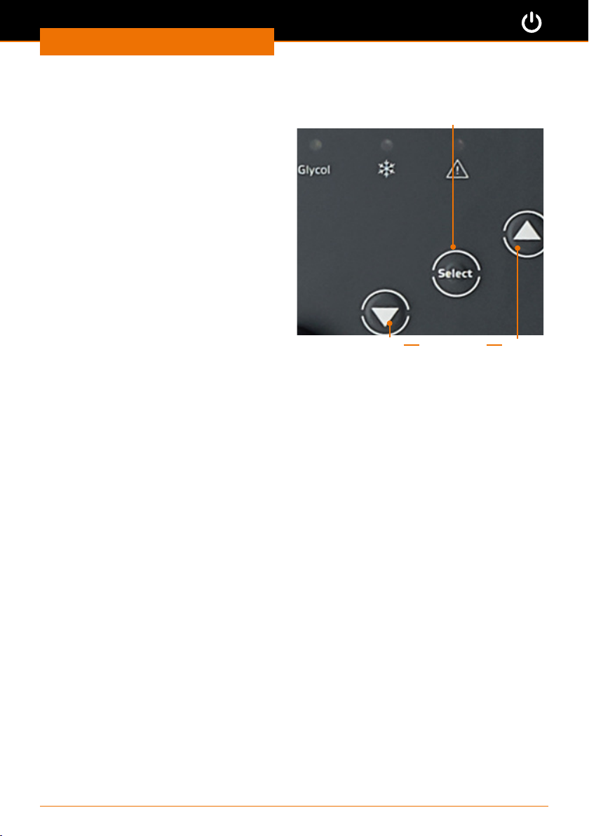
Hei-CHILL control panel..............................................................................11
Start Up 12
Setting up the device ........................................................................................12
Connecting/disconnecting the power cord ............................................................13
Switching the device on and o ..........................................................................13
Filling with thermal uid ....................................................................................14
Filling for the rst time ...............................................................................15
Menu navigation...............................................................................................17
Entering the temperature setting ........................................................................18
Setting the temperature limits.....................................................................18
Setting the temperature setpoint .................................................................20
Operation 21
Overview of menu structure...............................................................................21
Temperature control operation............................................................................22
Interfaces........................................................................................................23
RS 232 interface........................................................................................23
Interface commands ..................................................................................24
Cable and interface test for RS232 ...............................................................25
Alarm output.............................................................................................26
Autostart ..................................................................................................27
Restoring the factory settings.............................................................................28
Operating Manual

Contents
Cleaning and Maintenance 29
Cleaning..........................................................................................................29
Cleaning the device....................................................................................29
Cleaning the air lter..................................................................................29
Maintenance ....................................................................................................30
Maintenance .............................................................................................30
Maintenance intervals.................................................................................31
Checking the thermal uid ..........................................................................31
Troubleshooting 32
Malfunctions and troubleshooting........................................................................32
Assembly 33
Electrical connection .........................................................................................33
Peripheral connections ......................................................................................34
Overview of connections .............................................................................34
Connecting the alarm output .......................................................................34
Temperature control hoses..........................................................................35
Connecting the chiller to the external consumer.............................................36
Calibrating the temperature sensor ..............................................................37
Disassembly and Storage 38
Dismantling, transportation and storage ..............................................................38
Emptying the device ..................................................................................38
Transportation and storage .........................................................................38
Accessories and Spare Parts 39
Scope of delivery..............................................................................................39
Accessories......................................................................................................39
Attachments 40
Technical data ..................................................................................................40
Thermal uids ...........................................................................................41
Cooling unit ..............................................................................................42
Service 43
Contact / Technical Service ................................................................................43
Warranty.........................................................................................................44
Conrmation of condition...................................................................................45

About this Document
4
About this Document
Copyright
This operating manual is protected by copyright and is exclusively intended for the
internal use of the purchaser.
Handing over this operating manual to third parties, reproducing it in any type or form
–in part or in full – and utilizing and/or communicating its contents is prohibited without
prior written approval from the manufacturer.
Any violations will result in an obligation to provide compensation for damages. Other
claims remain unaected.
Version and variants
Version
This manual describes the function, operation and maintenance of the circulation chillers
High-CHILL 250, High-CHILL 350, High-CHILL 600 and High-CHILL 1200.
Version Alteration date
1.0 06/2018
Variants
The device is available in dierent variants. Certain features or functions are only avail-
able in specic product variants. These variants are described in this operating manual.
About this manual
This operating manual is an integral part of the device described here.
➜Carefully read through this operating manual and observe all of the
safety instructions and warnings notices.
➜Ensure that every user has carefully read the operating manual
before using the device for the rst time.
➜Store this operating manual so that it is accessible to all users at
all times.
➜Pass the operating manual on to any subsequent owner.
The current version of this operating manual can also be found at:
https://heidolph-instruments.com/en/service/downloads/operation
manuals#Rotary Evaporators/Chillers (High-CHILL 250-1200)
In addition, also observe the local regulations at the installation site.

5
About this Document
Symbols and keywords
Standardized symbols and signal words are used in this operating manual to warn against
any dangers and provide important instructions. These instructions must be strictly
observed to avoid accidents and damage.
The following terms and basic symbols are used:
Symbol Additional signal words / explanation
Warning
signs The yellow triangle indicates hazardous situations. It is used in combi-
nation with the following signal words:
DANGER:
Indicates a hazardous situation which, if not avoided, will result in
serious injury or death.
WARNING:
Indicates a hazardous situation which, if not avoided, may result in
serious injury or death.
CAUTION:
Indicates a hazardous situation which, if not avoided, may result in
property damage and minor or moderate injury.
Prohibitory
signs Prohibited:
The red circle indicates a situation that should be avoided under all
circumstances and which, if not avoided, may result in serious injury
or death.
Mandatory
signs Must be observed:
The blue circle indicates important information. Please observe this
information to avoid any property damage.
Other symbols used:
Symbol Description
➜Handling instruction, action required
✓Result of action
▪
▪
▪
List of information
a.
b.
c.
List of variants

Safety Instructions
6
Safety Instructions
General safety instructions
EU Declaration of Conformity
This device complies with the following EC-Directives*:
▪2006/42/EC Machinery Directive
▪2014/30/EU Electromagnetic Compatibility Directive
*Also see the attachment “EU Declaration of Conformity”.
The device has been manufactured according to state-of-the-art technology and in
compliance with recognized safety regulations. However, risks may still arise during
installation, operation and maintenance.
➜Please ensure that the operating manual is available at all times.
The device may only be used under the following conditions:
➜Only operate the device if it is in a technically perfect condition.
➜Only operate the device if you are properly aware of the risks and required safety
measures.
➜Only operate the device in accordance with the instructions given in this operating
manual.
➜If any information is ambiguous or missing, ask your superior or contact the manufacturer.
➜Do not operate anything on the device without authorization.
➜Only use the device in accordance with its intended use.
Intended use
The device is intended for use by trained and authorized personnel only.
The device is suitable for
the following uses:
▪Cooling of rotary evaporators: Hei-VAP Core, Hei-VAP
Expert, Hei-VAP Ultimate
▪Tempering and delivering non-combustible heat transfer
liquids in a closed circuit
▪Economical cooling as alternative to tap water systems
The device may be
operated in research
laboratories, other labora-
tories and production
facilities in the following
sectors:
▪Chemistry
▪Pharmacy
▪Biology
▪Environmental analytics
▪Basic research
▪Similar research laboratories
Reasonable foreseeable misuse
Any use which deviates from the device‘s intended use is considered to be improper. The
manufacturer is not liable for damage that occurs as a result. The risk is borne by the
operator alone.
Amongst other things, the following uses are considered to be foreseeable misuse:
▪Operation of the device without heat transfer liquid
▪Incorrect connection of tubes
▪Placement of the device on a tabletop surface, only permitted for Hei-CHILL 250 and
Hei-CHILL 350
▪Setting an incorrect pump pressure
▪Operation of the device with a glass reactor without overpressure protection
▪Chilling foodstus

7
Safety Instructions
Installation
Electrical safety
▪The device may only be connected up if the available power supply voltage corre-
sponds to the information stated on the rating plate for the device.
▪The power supply connection must be easily accessibly at all times.
▪An RCD circuit breaker (residual current circuit breaker) must be tted to the
electrical system in the building so that the device is disconnected from the power
circuit in the event of a fault.
▪Repairs may only be performed by electricians authorised by Heidolph Instruments.
▪Never operate the device with a damaged power cord.
▪Always turn the device OFF and disconnect the power cord before carrying out any
maintenance or repair work.
Thermal uids
▪The device is exclusively designed for nonammable thermal uids in Class I
according to DIN 12876-1.
▪Each thermal uid covers a specic temperature range. This temperature range must
match the temperature range of your application. If these temperatures are exceeded
or undercut, serious hazards to health or environment can be caused
(also see chapter “Attachment, Technical data”, section “Thermal uids”).
▪We recommend to use the Heidolph thermal uid. This has been tested and approved
by Heidolph Instruments.
▪The safety data sheet must be consulted for the intended use of the device.
Tubes
▪Besides material durability please note, that permissable temperature range and
maximum pressure must match with your application when selecting tubes for
connecting your periphery devices.
▪We recommend to use the Heidolph tubes. These have been tested and approved by
Heidolph Instruments.
Qualications of personnel
▪The device may only be operated by trained personnel.
▪The device may only be operated by persons who have been instructed and super-
vised in its proper use by trained specialist personnel.
▪The device may only be operated by specialist personnel who are above the legal
minimum age.
▪Other persons may only work on the device under the constant supervision of experi-
enced and trained specialist personnel.
▪This operating manual must be read and understood by all persons working with the
device.
▪Personnel must receive safety training that ensures responsible and safe working
practices.

Safety Instructions
8
Operating company’s obligations
Installation site
▪The device must be installed in a suitable location.
▪The device must be installed on a rm and stable surface.
▪Ensure that the device and all of its components and connections are easily accessible
at all times.
▪The front and side vents of the device must be a minimum of 40 cm (16 inch) away
from walls or vertical surfaces so air ow is not restricted.
▪It is not permitted to place or store any objects such as accessories, tools or
chemicals within this clearance area during operation.
▪All screw connections must be securely tightened.
▪It is not permitted to operate the device near to highly ammable or explosive substances.
▪Only operate the device (depending on the substances being used) in conjunction
with an extractor hood (see DIN EN 14175 and DIN 12924).
▪The device is designed for indoor use only and under the following ambient condi-
tions:
Ambient temperature 5 - 31 °C at 80 % relative humidity
32 - 40 °C decreasing linearly to a
maximum 50 % relative humidity
Installation altitude 0 - 2,000 m above sea level
Contamination level 2
Overvoltage category II
Permissible supply
deviations
± 10 %
▪If the device is operated in corrosive atmospheres, the service life of the device will
decrease based on the concentration, duration and frequency of the exposure to the
corrosive atmosphere e.g. concentrated hydrochloric acid (HCI).
Modications to the device
▪It is not permitted to make any unauthorised modications or changes to the device.
▪Do not attach or install any parts that have not been approved by the manufacturer.
▪Unauthorized modications or changes will void the EC Declaration of Conformity for
the device and operation of the device will no longer be permitted.
▪The manufacturer is not liable for any damage, dangers or injuries that result from
unauthorized modications and changes or due to the non-observance of the instruc-
tions in this manual.
Safety of personnel
➜Ensure that the device is only operated by qualied specialist personnel and trained
employees.
➜Observe the following instructions to avoid any personal injuries and property damage:
- Laboratory regulations
- Accident prevention regulations
- Hazardous Substance Act
- Other generally accepted occupational health and safety regulations
- Local regulations

9
Safety Instructions
Safety during use
➜Wear the appropriate clothing when working on the device (protective clothing,
protective glasses and, if necessary, safety gloves).
➜Do not use the device in potentially explosive areas. The device is not protected
against explosion. There is no explosion or ATEX protection available.
➜Do not carry out work with naked ames in the vicinity of the device (risk of
explosion).
➜Do not operate or assemble devices in the vicinity which are emission or radiation
sources (electromagnetic waves) for the frequency range (3*1011 Hz to 3*1015 Hz).
➜Do not operate or assemble appliances in the vicinity of the device which constitute
emission or radiation sources for ionizing radiation or in the ultrasonic range.
➜Do not operate the device where adiabatic compression or shock waves might occur
(shock wave combustion).
➜Attach all tube connections securely to ensure safe operation.
➜Connect all cables and tubes without kinks and locate them outside the operating and
danger zone.
➜Do not spill liquids over the device or any parts of it.
➜Remove any accidentally spilled liquids immediatly.
➜Eliminate errors immediately.
➜Avoid putting pressure on the display when you are not operating the device.
➜Do not use abrasive material to clean the surface. Only wipe with damp cloth.
➜Always switch the device OFF after use.
Disposal
Refrigerant
➜The device may only be disposed of by a qualied refriger-
ation technician.
➜Dispose of the refrigerant in accordance with EC Directive
215/2067 in combination with 517/2014/EC.
(Type und quantity of the refrigerant can be seen on the
rating plate; also see chapter „Attachement, Technical data”,
section „Refrigerant unit”.)
Device and packaging
➜Check the device components for hazardous substances and
solvents.
➜Clean all components before disposal.
➜Dispose of the device in accordance with the relevant
national regulations.
➜Dispose of the packaging material in accordance with the
appropriate national regulations.

Device Description
10
Device Description
Device overview
Device overview Hei-CHILL 250 / 350 / 600 / 1200
Filling pipe with
cover
Fill level indicator
Front cover
with ventilation
openings
Control panel
Hei-CHILL 250 / 350
4 feet
Hei-CHILL 600 / 1200
4 castors with locking brake
ON/OFF switch

Device Description
11
Hei-CHILL control panel
Error LED:
Device fault
ON/OFF switch
Fill level LED:
Thermal uid
missing
Cooling LED:
Cooling system
active
Display
Down arrow button:
navigate in menu
Up arrow button:
navigate in menu
Conrmation button:
Conrm menu
selection
Temperature display

Start-Up
12
Start Up
Setting up the device
Danger:
Risk of poisoning!
Toxic vapours may be emitted depending on the thermal uid being
used and the type of operation.
Ensure that these vapours are extracted adequately.
Warning:
Risk of crushing on the Hei-CHILL 600 and Hei-CHILL 1200
The chillers are set up on the oor and tted with castors to make
them easier to manoeuvre. As a result, the device could roll away and
possibly tip over.
Set up the device on a level, non-slip surface with sucient load-
bearing capacity!
Secure the device against rolling away by applying the locking brake!
Caution:
Possible damage to the cooling system
The liquid from the compressor may leak into the circulation system for
the thermal uid if the device is not set up in an upright position.
The device may not be tilted. Only set up, move and operate the
device in an upright position.
Caution:
Damage to the device
The device may overheat in the event of insucient airow.
Maintain a minimum distance of 40 cm between the ventilation grille
and walls or other vertical surfaces.
▪The chiller can be set up lower than the apparatus to be cooled.
In this case the pump must be switched on and all tubes must be
checked for tightness. Otherwise thermal liquid may overow or
discharge.
▪As long as the process is operated as a closed circuit, there is no
danger of the device overowing when topping up the thermal uid.
▪You can position multiple devices next to one another.
➜Set up the device on a solid, smooth, level and temperature-resistant surface.
➜Clean the installation surface and the feet or castors on the device at regular
intervals.
➜Apply the locking brake on those devices tted with castors to prevent the device
rolling away.
➜Do not place any heavy objects on the device.
Hei-CHILL 250 and Hei-CHILL 350
The devices can be set up on an even surface.
➜Carry the device by gripping underneath the device.

Start-Up
13
Hei-CHILL 600 and Hei-CHILL 1200
The devices may only be set up on the
oor.
➜Release the locking brake on the
castors by pressing the lever
downwards to [O].
➜Apply the locking brake to the castors
by pressing the lever upwards to [On]. Locking brake
applied [ON]
Locking brake
released [OFF]
Connecting/disconnecting the power cord
Connecting the power cord
The power cord has a three-pole
connector.
Power cordPower cord connector
The device socket is located on the rear of
the device.
✓The device is switched o.
➜Insert the power cord connector into
the device socket.
✓The connector has been securely
inserted when it has been pushed in
up to the stop.
➜Now insert the power cord plug into
the power socket.
Device socket
Disconnecting the power cord
➜First, remove the plug from the power socket.
➜Then disconnect the power cord connector from the device.
Switching the device on and o
Switching on the device
➜Press the toggle switch upwards
to “I”.
✓The device is switched on.
Switching o the device
➜Press the toggle switch downwards to
“O”.
✓The device is switched o. On/o switch: ON On/o switch: OFF

Start-Up
14
Filling with thermal uid
Danger:
Risk of re
If the device is lled with a thermal uid with a very low ash point, it
could catch re under certain circumstances.
Only use thermal uids with a ash point that is at least 20 K above
the temperature range for the application. Do not use any ethanol as
an additive because it is a highly ammable substance.
Warning:
Risk of electric shock
If the device is overlled, thermal uid may overow into the device
and cause the device to short circuit.
Ensure that the device is not overlled. Carefully monitor the ll level
indicator and the thermal expansion of the thermal uid.
Warning:
Risk of electric shock
If the device is lled in a careless manner, thermal uid may splash
into the device and cause the device to short circuit.
Use a funnel for the lling process. Avoid splashing the thermal uid.
Warning:
Risk of poisoning! Risk of injury!
When handling chemically prepared thermal uids, any splashes could
cause injuries to areas of bare skin.
Always wear safety goggles, protective gloves and protective clothing
when lling the chiller.
Caution:
Possible damage to the device
If you operate the device without thermal uid, the cooling circuit
pump could overheat and thus damage the device.
Only operate the device if it has been suciently lled with thermal
uid.
The thermal uid from Heidolph is suitable for all standard applications.
It covers a temperature range from minus 30 °C to plus 90 °C. (See
chapter “Spare parts and accessories, Accessories”)

Start-Up
15
Filling for the rst time
Depending on the version of the device, the reservoir for the thermal uid can hold
between 2-14 litres (see chapter “Attachments, Technical data”). The reservoir on the
device is lled with thermal uid from above.
Filling of the device is supported by a software program. If the ll level is too low:
▪the pump and cooling unit will not start
▪FILL will appear on the display and the ll level indicator will light up after the device
is switched on.
➜Connect up your external consumer
(see chapter “Assembly, Peripheral
connections”).
➜Close the drain screw by turning it to
the right as far as it will go.
Drain screw
➜Attach a suitable hose with an inner
diameter of
Ø 8 mm to the overow pipe on the
device.
➜Place the hose into a suitable container
to capture any overowing thermal
uid.
Overow pipe
If air penetrates into the temperature control circuit while lling the
device – e.g. due to an open or damaged bleed valve – the reservoir
and also the connected consumer could empty.
Ensure that you use a suciently large container for the overow pipe.
➜Switch the device ON.
✓A signal tone sounds.
✓The software version will be shown on
the display, followed by “FILL”.
➜Carefully remove the cover for the
lling pipe by pulling it upwards (no
screw connection).
➜Carefully ll the reservoir with thermal
uid via the lling pipe with the aid of
a funnel.
Sealing cap for reservoir
Filling pipe for reservoir

Start-Up
16
▪The maximum ll level for
the device is shown by the
upper arrow.
▪The minimum ll level for the
device is shown by the lower
arrow.
The ll level indicator should
not rise above the maximum
lling level.
➜Observe the ll level indicator and
ll the device up to the maximum ll
level.
Min. level
Max. level
➜Press the conrmation button when
the maximum ll level has been
reached or sucient uid has been
added.
✓The pump starts.
✓The current temperature is shown on
the display.
✓The ll level will now fall because the
external consumer is being lled.
➜Carefully rell the thermal uid.
✓If the ll level falls too far, the device
will automatically switch to FILL mode
and the pump and cooling unit will be
switched o.
➜Continue to ll the device until the ll
level indicator no longer falls.
Conrmation button
✓The reservoir has been lled suciently when the ll level settles between the
minimum and maximum marks on the ll level indicator.
➜Close the reservoir by carefully pushing the cover into the lling pipe.

Start-Up
17
Menu navigation
The menu is divided into a main menu and
2 submenus.
Use the conrmation button to access
the next menu and also to save changed
values where relevant.
Use the arrow buttons to move up and
down through the parameters in the
menu and to change the values set for the
parameters in the submenu.
Main menu
The current temperature of the device is
shown here.
Submenus 1 and 2
You can select the dierent parameters
and change the values where relevant
here.
Conrmation button
up arrow buttons down
➜Switch the device ON.
➜Press the conrmation button.
✓You will call up submenu 1.
➜Press the up ˆor down ˇarrow buttons.
✓The dierent parameters will be displayed in sequence (see chapter “Operation,
Overview of menu structure”).
➜Press the conrmation button to select a parameter.
✓You will call up submenu 2.
✓The set value for the selected parameter will be displayed.
➜Press the up ˆor down ˇarrow buttons.
✓The set value will be changed upwards or downwards.
➜Press the conrmation button to conrm the value.
✓The set value will be changed upwards or downwards.

Start-Up
18
Entering the temperature setting
Before placing the chiller into operation, the desired temperature setting needs to be
entered depending on the thermal uid being used.
Warning:
Risk of poisoning! Risk of injury!
Each individual thermal uid covers a certain temperature range. If
the temperature exceeds or falls below this temperature range, it
could damage the device and cause the thermal uid to escape. There
is a risk of slipping and poisoning in the event of escaping thermal
uids.
Check the permissible temperature range for the thermal uid being
used and carefully set the temperature limits on the device.
The desired cooling temperature is maintained by dening the following two variables:
▪Temperature limit:
This value denes the upper and lower maximum values that must not be exceeded.
If the temperature exceeds or falls below these values, a warning signal will sound.
▪Temperature setpoint:
This value denes the cooling temperature for the thermal uid. Until this setpoint is
achieved, the current temperature will uctuate above and below this setpoint and
thus also between the upper and lower temperature limits.
Setting the temperature limits
Both values for the temperature limits are dependent on the thermal uid being used.
Possible setting range:
Lower temperature limit “Lo” -12° C to 41° C
Upper temperature limit “Hi” -11° C to 42° C
Sensible temperature limits are:
Heidolph thermal uid Temperature limits: “Lo” min. -12 °C
(also see chapter “Spare parts and accessories,
Accessories”)
“Hi” max. 42 °C

Start-Up
19
Setting the upper temperature limit
✓The device is switched on.
➜Press the conrmation button.
➜Press the down arrow button ˇonce.
✓“Hi” appears on the display.
➜Press the conrmation button.
✓The display ashes.
➜Press the up ˆ or down ˇ arrow
buttons to set the desired value.
➜Conrm the desired value with the
conrmation button.
✓The set value is saved.
✓You return to the main menu.
Upper temperature limit
If you do not press any buttons for more than 4 seconds, the changed
values will be saved. You return automatically to the main menu.
Setting the lower temperature limit
✓The device is switched on.
➜Press the conrmation button.
➜Press the down arrow button ˇtwice.
✓“Lo” appears on the display.
➜Press the conrmation button.
✓The display ashes.
➜Press the up ˆor down ˇarrow
buttons to set the desired value.
➜Conrm the desired value with the
conrmation button.
✓The set value is saved.
✓You return to the main menu.
Lower temperature limit

Start-Up
20
Setting the temperature setpoint
The temperature range for the setpoint is automatically limited by
the temperature limits. It can be set to a maximum of 2 °C below the
upper temperature limit and 2 °C above the minimum temperature
limit.
In the case of a temperature setpoint or current temperature < 5
°C, the yellow LED on the device will light up. It warns you about the
possible incorrect use of the thermal uid and resulting damage to the
device.
➜Press the conrmation button.
➜Use the arrow button to select the
submenu for entering the setpoint
“Set”.
➜Set the desired temperature setpoint.
➜Save the temperature setpoint with the
conrmation button.
Entered setpoint
If the temperature setpoint you have entered is outside of the dened
temperature limits, a warning signal will sound. The value will not be
saved.
Table of contents
Languages:
Other Heidolph Chiller manuals
Popular Chiller manuals by other brands

Applied Thermal Control
Applied Thermal Control KTR instruction manual

Cornelius
Cornelius Chiller ("CH" Series) CH 250 Operator's & installation manual

Borg & Overstrom
Borg & Overstrom u1 Install & Operation Manual

lancer
lancer PRESTO Installation, operation & service manual

McQuay
McQuay Seasonpak ALR-035A Installation and maintenance data

Brooks
Brooks Polycold MaxCool Series Installation and operation manual