HEIN-WERNER AUTOMOTIVE HW93300 Instructions for use

Operating Instructions & Parts Manual
Model Number Capacity
HW93300 25 Ton
HW93301 25 Ton
Shop Presses
SFA Companies
10939 N. Pomona Ave. Kansas City, MO 64153
Read this manual and follow all the Safety Rules and Operating Instructions before using this product
HW93300-MR rev 12/07
This is the safety alert symbol. It is used to alert you to potential personal injury hazards.
Obey all safety messages that follow this symbol to avoid possible injury or death.
!

2
BEFORE USE
1. Inspect before each use. Do not use if bent, broken or cracked components are noted. Check for and tighten any loose
assemblies.
2. Verify that the product and the application are compatible, if in doubt call Hein-Werner Technical Service (816) 891-6390.
3. Before using this product, read the operator's manual completely and familiarize yourself thoroughly with the product, its
components and recognize the potential hazards associated with its use.
• Study, understand, and follow all instructions provided with and on this device before use.
• Do not exceed rated capacity.
• Burst hazard exists if hose or connection pressure exceeds rated pressure.
• Use the device only on a hard, level surface.
• Always monitor the pressure gauge while operating.
• Always inspect hoses and connections for damage prior to use.
• Always wear safety goggles when working on or near this equipment.
• Keep hands, feet and all other body parts away from loading area.
• Never leave loaded press unattended.
• Projectile hazard! Ensure workpiece is center loaded, and a safety shield is installed around workpiece to protect against
projectiles.
• Do not modify this device beyond installing a shield to protect against projectiles.
• Ensure the user is familiar with the controls and operational characteristics of this product and aware of the potential
hazards associated with its use.
• Failure to heed these markings may result in personal injury and/or property damage.
!WARNING
SAFETY and GENERAL INFORMATION
Save these instructions. For your safety, read, understand, and follow the information provided with and on this product
before using. The owner and/or operator of this equipment shall have an understanding of this equipment and safe operating
procedures before attempting to use. The owner and/or operator shall be aware that use and repair of this product may
require special skills and knowledge. Instructions and safety information shall be conveyed in the operator's native language
before use of this product is authorized. If any doubt exists as to the safe and proper use of this product, remove from service
immediately.
Inspect before each use. Do not use if there are broken, bent, cracked or otherwise damaged parts (including labels). If
the press has been or suspected to have been subjected to a shock load (a load dropped suddenly and unexpectedly upon
it), discontinue use until checked out by an authorized factory service center. Owners and operators of this equipment shall
be aware that the use of this equipment may require special training and knowledge. It is recommended that an annual
inspection be done by qualified personnel and that any missing or damaged parts, decals, warning/safety labels or signs be
replaced with factory authorized replacement parts only. Any press that appears to be damaged in any way, is worn or
operates abnormally shall be removed from service immediately. Labels and Manual are available from manufacturer.
PRODUCT DESCRIPTION
Hein-Werner Shop Presses are designed for automotive, truck, implement, fleet, and industrial repair shops where press-
ing, bending, straightening, forming is required. Each press includes a pressure gauge which provides for monitoring the
applied pressing force.
Typical applications include installation and removal of alternator and power steering pump bearings, axle bearings,
transmission bearings, seal, driveshaft bearings and u-joints and others. It is not intended for use as an assembly table or
as fixture stand used to secure a large, final assembly component. Refer to Cylinder and Pump manuals for more information.
!WARNING: To reduce the risk of personal injury and/or property damage, ensure that the rated working pressure of
each pressurized attachment be equal to or greater than the rated working pressure developed by the hydraulic pump.

3
SPECIFICATIONS
Shop Press:
Manual Pump (Hand pump):
Air Pump:
Cylinder:
Model
No. Type
HW93300 P1000 Manual 6'
HW93301 PA1500 Air 10'
Min.
Working
space
Max.
Working
Space
25 Ton 6" H2506 11 1/2" 71" x 48" x 28" 4 1/2" 47 1/4"
Pump Hydraulic
Hose
Length
Bed
Width
Press Size
(H x W x L)
Model No. Load
Capacity Stroke
Cylinder
Model
No.
Model Capacity
.
.
(ton)
Stroke
.
.
(in)
Cylinder
Effective
Area
(in2)
Oil
Capacity
.
(in3)
Collapsed
Height
.
(in)
Extended
Height
.
(in)
Outside
Dia
.
(in)
Ram
Plunger
Dia.
(in)
Saddle
Dia.
.
(in)
Collar
Thread
Collar
Thread
Length
(in)
H2506 25 5.94 5.14 30.53 10.79 16.73 3.35 2.24 0.98 3 5/16"-12 1.93
1st Stage 2nd Stage 1st Stage 2nd Stage
P1000 61 200 10,000 0.81 0.14 3/8"-18NPTF 13
Oil Outlet Port Weight
(lb.)
Model
Usable
Oil
Capacity
(in3)
Pressure Rating
(psi)
Oil Displacement
(in3)
No Load Load
PA1500 91.5 10,000 65 11 90-175 18
Input Air
Pressure Range
(psi)
Weight
,
(lb.)
Model
.
.
Usable Oil
Capacity
(in3)
Pressure
Rating
(psi)
Oil output Flow Rate
(in3/min)
ASSEMBLY
1. Attach base sections to upright channels with 4 bolts and nuts.
2. Attach lower cross member to upright channels with 4 bolts and nuts.
3. Ensure bed frame at lowest position and winch cable is slack.
4. Install the winch assembly to the press using 3 bolts, washers and nuts.
5. Secure cylinder to the cylinder adapter plate, and mount the adapter plate to upper cross member with provided bolts,
washers and nuts.
6. Secure the pump bracket to the upright channel with bolts, nuts & washers provided.
7. Connect the pressure gauge and the hydraulic hose to the gauge adapter, then connect the gauge adapter to pump.
Important: Ensure thread tape or compound is use on connections.
8. Place the pump on the pump bracket and connect the other end of hydraulic hose to cylinder.
8.a. When using manual pump, bolt pump to pump bracket.
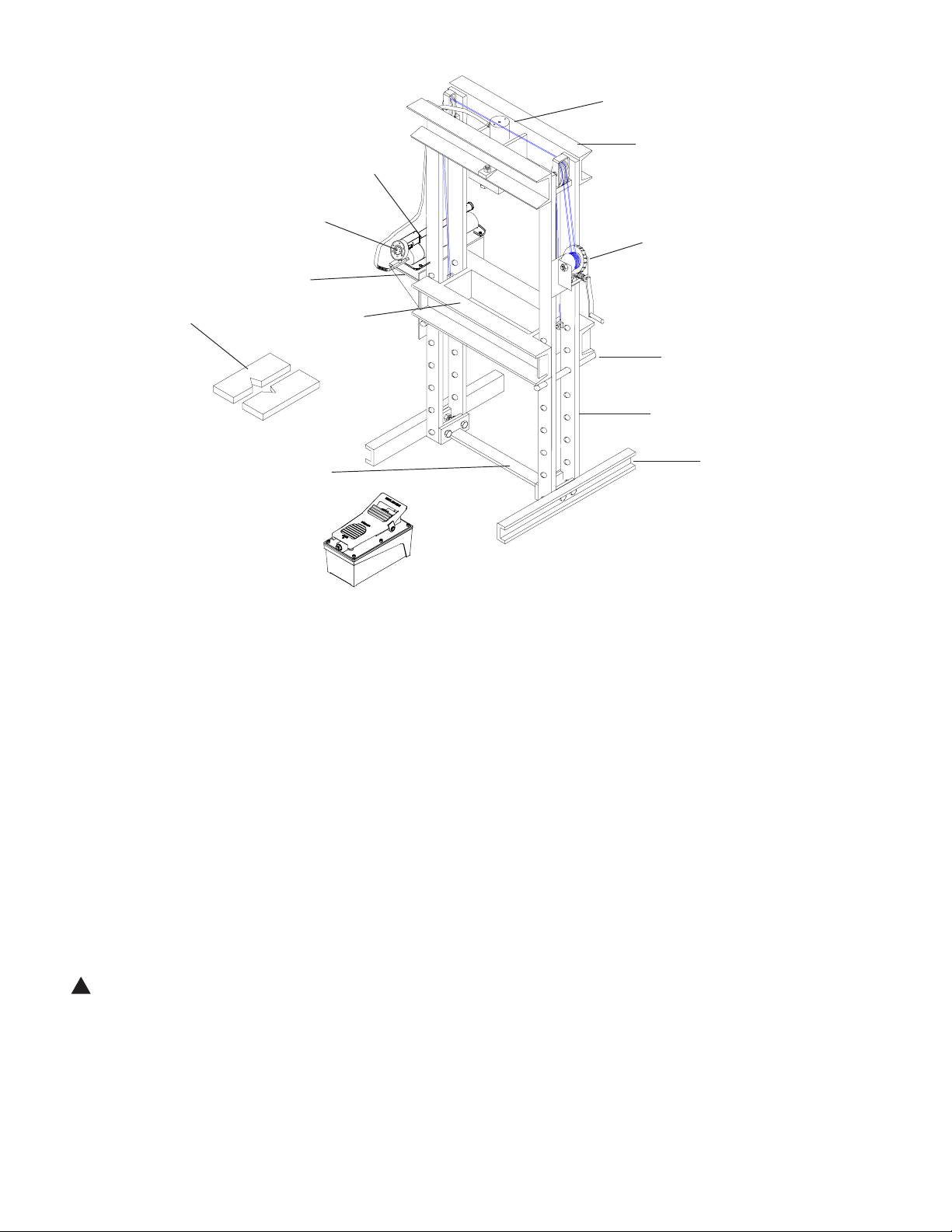
Figure 1 - Typical Shop Press Components
Cylinder
Winch
Upright Channel
Support Pin
Base
Upper Cross Member
Manual Pump
Pressure Gauge
Bed Frame
Arbor Plates
Lower Cross Member
Air Pump for Model HW93301:
4
(Optional, not
included with
the press)
Before disassemble, slide bed frame section down, into its lowest position.
!
Pump Bracket
(Model HW93300)

OPERATION
Projectile Hazard! Ensure that workpiece is centerloaded and secure. Reduce risk of flying debris by carefully
following all operating instruction. Know your press and hazards associated with its use. Keep hands and feet from
bed area at all times.
1. Insert the support pins to desired height, then lower the bed frame using the winch until the cable is slack and the bed
frame is resting fully on the support pins.
2. If needed, place arbor plates on the bed frame (optional, not included).
3. Place workpiece on the bed frame, using every precaution necessary to ensure your safety and prevent property
damage.
4. Operate the pump:
a) Manual Pump: (model HW93300)
Close the release valve by turning it clockwise, and pump the handle to extend the cylinder ram. To retract, simply
open the release valve of pump.
b) Air Pump: (model HW93301)
Connect to suitable air supply, press on the foot pedal to extend the cylinder ram. To retract, simply press the
release valve by stepping on the raised, stirrup shaped portion of the foot pedal.
Note: Never operate pump with hose disconnected from cylinder. If operated in this condition, the hydraulic hose and
connections become pressurized. This increases burst hazard.
5. Apply load to workpiece. Do not overload the workpiece.
6. Stabilize workpiece in a manner which will not allow it to inadvertently fall from the bed once the load is removed.
7. Once cylinder has fully retracted, remove workpiece.
Note: To protect your cylinder, do not continue to operate pump after cylinder plunger is fully extended or retracted.
MAINTENANCE
Please refer to cylinder and pump's manual for maintenance and how to add/change hydraulic oil. For best results,
change the oil once a year. Use only good quality hydraulic oil. We recommend HW93291 for manual and air pumps.
Lubrication
A periodic coating of light lubricating oil to pivot points and hinges will help to prevent rust and assure assemblies move
freely.
Storage
Depressurize the hydraulic system, disconnect the hydraulic hose and lower the bed frame to lowest position.
REPLACEMENT PARTS (refer to page 7)
Not all components of the Press are replacement items, but are illustrated as covenient reference of location and position
in the assembly sequence. When ordering parts, give Model number, serial number and parts description. Call or write for
current pricing: Hein-Werner Customer Support, 10939 N. Pomona Ave. Kansas City, MO 64153; Tel:(816)891-6390;
5
!
!
Risk of serious eye injury from projected or blown debris. Reduce risk by wearing safety goggles when working
with or around press.
Use only manufacturer provided attachments and accessories! Ensure all cylinder attachments are securely
threaded into the cylinder. When using bearing punch and other adapters, center the load on workpiece.

6
TROUBLESHOOTING
A system failure may or may not be the result of a pump malfunction. The following information is intended to be
used as an aid in determining if a problem exist.
Symptom Possible Causes Corrective Action
Erratic ram action • Air in system or pump cavitation
• External leak
• Internal hydraulic leak
• Follow pump instructions for
bleeding air
• Tighten all connections
• Contact Service Center
Ram extends partially • Hydraulic oil level too low in pump
• Load is above the capacity of
system
• Ram is sticking or binding
• Fill and bleed the system
• Match the capacity to application
• Contact Service Center
Ram moves slower than normal • Loose connection or coupler
• Restricted hydraulic line or fitting
• Pump not working correctly
• Ram seals leaking
• Tighten connection or coupler
• Clean and replace if damaged
• Check pump operating instructions
• Replace cylinder
Ram leaks hydraulic fluid • Worn or damaged seals • Contact Service Center
Ram will not retract or retracts
slower than normal
• Linkage binding
• Loose couplers
• Malfunctioning coupler
• Weak or broken retraction springs
• Ram damaged internally
• Pump reservoir too full
• Lubricate all moving parts
• Tighten couplers
• Depressurize pump and hose,
remove application, then replace a
new coupler
• Contact Service Center
• Contact Service Center
• Drain hydraulic fluid to correct level
Pump or ram fails to maintain
pressure
• Overload condition
• External leak
• Internal hydraulic leak
• Ram seals leaking
• Pump or valve malfunctioning
• Remedy overload condition
• Tighten all connections
• Contact Service Center
• Contact Service Center
• Check pump operating instructions

7
Figure 2: Replacement Parts Illustration for Model HW93300 and HW93301
Replacement Parts List for 25 Ton Press Model No. HW93300 & HW93301
11
13 1
3
2
4
5
6
8
7
9(b)
15
16
10
14
17(a)
P1000
Hand Pump for
model HW93300
17(b)
PA1500 Air Pump
for model HW93301
12
9(a)
(for HW93300)
(for HW93301)
HW93300 HW93301
1 300-002-001 300-002-001-B Frame with Winch & Pump Bracket 1
2 Bed Frame 1
3 Support Pin 2
4Base 2
5 Lower Cross Member 1
6Winch1
7Pulley3
8 Cable 2
9 300-002-009 300-002-011 Pump Bracket 1
10 Cylinder Adapter Plate 1
11 25 Ton Cylinder 1
12 Male Half Coupler, 3/8" 1
13 CS3838 CS3838C Hydraulic Hose, 3/8"ID 1
14 Dry Pressure Gauge, 2.5", 10,000psi 1
15 Gauge Adapter 1
16 Arbor Plates, 25Ton 1
17 P1000 PA1500 Pump 1
A
P25
H2506
CH38M
GD2514
CF3814
300-002-006
300-002-007
300-002-008
300-002-012
N/A
300-002-003
300-002-004
300-002-005
Item Part No. for Model Description Qty
18 300-002-016 N/A Pump Mounting Hardware Kit 1

TWO YEARS LIMITED WARRANTY
For a period of two (2) years from date of purchase, SFA Companies will repair or replace, at its option, without charge, any
of its products which fails due to a defect in material or workmanship under normal usage. This limited warranty is a
consumer's exclusive remedy.
Performance of any obligation under this warranty may be obtained by returning the warranted product, freight prepaid, to
SFA Companies Warranty Service Department, 10939 N. Pomona Ave., Kansas City, MO 64153.
Except where such limitations and exclusions are specifically prohibited by applicable law:
(1) THE CONSUMER'S SOLE AND EXCLUSIVE REMEDY SHALL BE THE REPAIR OR REPLACEMENT OF DEFECTIVE
PRODUCTS AS DESCRIBED ABOVE
(2) SFA COMPANIES SHALL NOT BE LIABLE FOR ANY CONSEQUENTIAL OR INCIDENTAL DAMAGE OR LOSS
WHATSOEVER.
(3) ANY IMPLIED WARRANTIES, INCLUDING WITHOUT LIMITATION THE IMPLIED WARRANTIES OF MERCHANTABILITY
AND FITNESS FOR A PARTICULAR PURPOSE, SHALL BE LIMITED TO TWO YEARS, OTHERWISE THE REPAIR,
REPLACEMENT OR REFUND AS PROVIDED UNDER THIS EXPRESS LIMITED WARRANTY IS THE EXCLUSIVE
REMEDY OF THE CONSUMER, AND IS PROVIDED IN LIEU OF ALL OTHER WARRANTIES, EXPRESS OR IMPLIED.
(4) ANY MODIFICATION, ALTERATION, ABUSE, UNAUTHORIZED SERVICE OR ORNAMENTAL DESIGN VOIDS THIS
WARRANTY AND IS NOT COVERED BY THIS WARRANTY.
Some states do not allow limitations on how long an implied warranty lasts, so the above limitation may not apply to you.
Some states do not allow the exclusion or limitation of incidental or consequential damages, so the above limitation or
exclusion may not apply to you. This warranty gives you specific legal rights, and you may also have other rights which vary
from state to state.
SFA Companies
10939 N. Pomona Ave. Kansas City, MO 64153
816-891-6390
8
This manual suits for next models
1
Table of contents
Other HEIN-WERNER AUTOMOTIVE Power Tools manuals


Popular Power Tools manuals by other brands


Sparky Group
Sparky Group HD PROFESSIONAL X 85CES Plus Original instructions

Makita
Makita TW100D Series instruction manual

Tenma
Tenma 21-8240 user manual

KRESS
KRESS 180 AFT-D Original instructions

Atlas Copco
Atlas Copco ETP STB33-12-10-B Product instructions

Desoutter
Desoutter PT040-T6000-S10S user manual


