Heinzmann Theseus AT 01 User manual

Heinzmann GmbH & Co. KG
Engine & Turbine Controls
Am Haselbach 1
D-79677 Schönau (Schwarzwald)
Germany
Phone +49 7673 8208-0
Fax +49 7673 8208-188
www.heinzmann.com
V.A.T. No.: DE145551926
HEINZMANN®
Electronic Speed Governors
Analogue Generator Power Controller
and Synchronizer
THESEUS AT 01
Copyright 2004 by Heinzmann GmbH & Co KG. All rights reserved. This document may not be reproduced or handed on to third parties.
Manual E 98 004-e / 08-06

Read this entire manual and all other publications appertaining to the
work to be performed before installing, operating or servicing your
equipment.
Practice all plant and safety instructions and precautions.
Failure to follow instructions may result in personal injury and/or
damage to property.
HEINZMANN will refuse all liability for injury or damage which
results from not following instructions
Please note before commissioning the installation:
Before starting to install any equipment, the installation must have been
switched dead!
Be sure to use cable shieldings and power supply connections meeting
the requirements of the European Directive concerning EMI.
Check the functionality of the existing protection and monitoring
systems.
To prevent damages to the equipment and personal injuries, it is
imperative that the following monitoring and protection systems
have been installed:
Overspeed protection acting independently of the speed governor
Overtemperature protection
HEINZMANN will refuse all liability for damage which results from
missing or insufficiently working overspeed protection
Generator installation will in addition require:
Overcurrent protection
Protection against faulty synchronization due to excessive frequency,
voltage or phase differences
Reverse power protection
Overspeeding can be caused by:
Failure of the voltage supply
Failure of the actuator, the control unit or of any accessory device
Sluggish and blocking linkage
Warning
Danger
Danger
Danger!
High
Voltage
Danger

Electronically controlled injection (MVC) will in addition require
to observe the following:
With Common Rail systems a separate mechanical flow limiter must
be provided for each injector pipe.
With Pump-Pipe-Nozzle (PPN) and Pump Nozzle (PNE) systems fuel
release may be enabled only by the movement of control piston of the
solenoid valve. This is to inhibit fuel from being delivered to the
injection nozzle in case of seizure of the control piston.
The examples, data and any other information in this manual are
intended exclusively as instruction aids and should not be used in any
particular application without independent testing and verification by
the person making the application.
Independent testing and verification are especially important in any
application in which malfunction might result in personal injury or
damage to property.
HEINZMANN make no warranties, express or implied, that the
examples, data, or other information in this volume are free of error,
that they are consistent with industry standards, or that they will meet
the requirements for any particular application.
HEINZMANN expressly disclaim the implied warranties of
merchantability and of fitness for any particular purpose, even if
HEINZMANN have been advised of a particular purpose and even if a
particular purpose is indicated in the manual.
HEINZMANN also disclaim all liability for direct, indirect, incidental
or consequential damages that result from any use of the examples,
data, or other information contained in this manual.
HEINZMANN make no warranties for the conception and engineering
of the technical installation as a whole. This is the responsibility of the
user and of his planning staff and specialists. It is also their
responsibility to verify whether the performance features of our devices
will meet the intended purposes. The user is also responsible for correct
commissioning of the total installation.
Warning
Warning
Danger


Contents
THESEUS Analogue AT 01
Contents
Page
1 Safety Instructions and Related Symbols ........................................................................... 1
1.1 Basic Safety Measures for Normal Operation................................................................. 2
1.2 Basic Safety Measures for Servicing and Maintenance.................................................. 2
1.3 Before Putting an Installation into Service after Maintenance and Repair Works ......... 3
2 Application............................................................................................................................. 4
2.1 General ............................................................................................................................ 4
2.2 Load Measuring and Share Device.................................................................................. 4
2.3 Synchronizer Device ....................................................................................................... 4
2.4 Load Ramp Device.......................................................................................................... 5
3 Block Diagram....................................................................................................................... 6
4 Mode of Operation................................................................................................................ 7
4.1 General ............................................................................................................................ 7
4.2 Load Measuring and Sharing Device.............................................................................. 7
4.3 Synchronizer Device ....................................................................................................... 8
4.4 Load Ramp Device.......................................................................................................... 8
5 Technical Data....................................................................................................................... 9
5.1 General ............................................................................................................................ 9
5.2 Load Measuring and Sharing Device.............................................................................. 9
5.3 Synchronizer Device ..................................................................................................... 10
5.4 Load Ramp Device........................................................................................................ 10
6 Electrical Connection.......................................................................................................... 11
6.1 Table of Terminal Connections and their Functions..................................................... 11
6.2 Connection of Bus Voltages and Current Transformers ............................................... 13
6.3 Connection with Control Unit of Series E 1 - F and E 2 - F ......................................... 14
6.4 Connection with Control Unit of Series E 6 up to E 40................................................ 14
6.5 Connection with Control Unit of Series E 2000............................................................ 15
6.6 Connection to more THESEUS Units AT 01 in Parallel Operation ............................. 15
6.7 Connection of Load Setpoint Potentiometer in Parallel Mains Operation.................... 16
6.8 Connection of Load Control Unit in Controlled Mains Supply Operation................... 16
6.9 Connection of External Base Load................................................................................ 17
6.10 Connection of External Load Limitation..................................................................... 17
6.11 Connection of External Droop, if necessary................................................................ 18
7 Measurement ....................................................................................................................... 19

Contents
THESEUS Analogue AT 01
8 Commissioning .................................................................................................................... 20
8.1 Mean and Position of Adjusting Potentiometers and Testpoints .................................. 20
8.2 Mean and Position of LED’s......................................................................................... 22
8.3 Initial Setting Up Procedure.......................................................................................... 24
8.4 Initial Setting of the Speed Governor............................................................................ 24
8.5 Adjustment of Synchronizer Device ............................................................................. 25
8.6 Adjustment of Load Sharing Device in Island Parallel Operation................................ 26
8.7 Adjustment of Load Share Device in Base Load Mains Operation .............................. 27
8.8 Adjustment of Load Sharing Device with Controlled Mains Supply............................ 29
8.9 Adjustment of Load Limitation..................................................................................... 29
8.10 Adjustment of Forward Power and Reverse Power Relays......................................... 30
8.11 Adjustment of Droop, if necessary.............................................................................. 30
8.12 Adjustment of Load Ramp Device.............................................................................. 31
9 Ordering Specification........................................................................................................ 33
10 Figure List.......................................................................................................................... 34
11 Order Specifications for Manuals.................................................................................... 35
1 Safety Instructions and Related Symbols
THESEUS Analogue AT 01 1
1Safety Instructions and Related Symbols
This publication offers wherever necessary practical safety instructions to indicate inevitable
residual risks when operating the engine. These residual risks imply dangers to
persons
product and engine
environment.
The symbols used in this publication are in the first place intended to direct your attention to
the safety instructions!
This symbol is to indicate that there may exist dangers to the engine, to
the material and to the environment.
This symbol is to indicate that there may exist dangers to persons.
(Danger to life, personal injury))
This symbol is to indicate that there exist particular danger due to
electrical high tension. (Mortal danger).
This symbol does not refer to any safety instructions but offers important notes for
better understanding the functions that are being discussed. They should by all
means be observed and practiced. The respective text is printed in italics.
The primary issue of these safety instructions is to prevent personal injuries!
Whenever some safety instruction is preceded by a warning triangle labelled “Danger” this is
to indicate that it is not possible to definitely exclude the presence of danger to persons,
engine, material and/or environment.
If, however, some safety instruction is preceded by the warning triangle labelled “Caution”
this will indicate that danger of life or personal injury is not involved.
The symbols used in the text do not supersede the safety instructions. So please do not
skip the respective texts but read them thoroughly!
Note
Warning
Dan
g
er
Danger!
High
V
olta
g
e

1 Safety Instructions and Related Symbols
2THESEUS Analogue AT 01
In this publication the Table of Contents is preceded by diverse instructions that
among other things serve to ensure safety of operation. It is absolutely imperative
that these hints be read and understood before commissioning or servicing the
installation.
1.1 Basic Safety Measures for Normal Operation
•The installation may be operated only by authorized persons who have been duly
trained and who are fully acquainted with the operating instructions so that they are
capable of working in accordance with them.
•Before turning the installation on please verify and make sure that
- only authorized persons are present within the working range of the engine;
- nobody will be in danger of suffering injuries by starting the engine.
•Before starting the engine always check the installation for visible damages and make
sure it is not put into operation unless it is in perfect condition. On detecting any faults
please inform your superior immediately!
•Before starting the engine remove any unnecessary material and/or objects from the
working range of the installation/engine.
•Before starting the engine check and make sure that all safety devices are working
properly!
1.2 Basic Safety Measures for Servicing and Maintenance
•Before performing any maintenance or repair work make sure the working area of the
engine has been closed to unauthorized persons. Put on a sign warning that
maintenance or repair work is being done.
•Before performing any maintenance or repair work switch off the master switch of the
power supply and secure it by a padlock! The key must be kept by the person
performing the maintenance and repair works.
•Before performing any maintenance and repair work make sure that all parts of engine
to be touched have cooled down to ambient temperature and are dead!
•Refasten loose connections!
•Replace at once any damaged lines and/or cables!
•Keep the cabinet always closed. Access should be permitted only to authorized
persons having a key or tools.

1 Safety Instructions and Related Symbols
THESEUS Analogue AT 01 3
•Never use a water hose to clean cabinets or other casings of electric equipment!
1.3 Before Putting an Installation into Service after Maintenance and Repair
Works
•Check on all slackened screw connections to have been tightened again!
•Make sure the control linkage has been reattached and all cables have been
reconnected.
•Make sure all safety devices of the installation are in perfect order and are working
properly!

2 Application
4THESEUS Analogue AT 01
2Application
2.1 General
The analogue generator power controller and synchronizer THESEUS AT 01 has been
designed to work in conjunction with any of the HEINZMANN analogue electronic
governors to make a complete generator management. It can also be used with competitors'
electronic governors by the addition of a small interface card.
The new concept of the AT 01 is the introduction of integrating load sharing,
synchronising and load ramping for soft switching load on and off inside one printed
circuit card which utilises a common set of voltage and current transformers. Costly wiring
between the single units are not necessary.
2.2 Load Measuring and Share Device
Isochronous load sharing is also incorporated using three phase voltage and current inputs
which are multiplied together to produce a true kilowatt output about all three phases. The
resultant kilowatt output is then fed into our standard load sharing concept that will allow
up to 15 engines to be parallelled together at the same time and share load to within ±2%.
There is a meter output 0-5V or 0-1 mA indicating kilowatts and also a forward power and
reverse power relay contact with LED indication. Standard load limiting inputs are
available, along with a new soft loading function which will allow isochronous loading and
unloading of an alternator parallel to an island or mains BUS with a base load facility.
2.3 Synchronizer Device
The analogue power controller has a full isochronous auto three phase synchroniser
incorporating frequency and phase correction with LED indication of frequency, phase,
capture angle and breaker closure. There is also a safety feature built into the synchroniser
that detects phase rotation and will only allow the breaker to close if the generator is up to
frequency, in phase (within a predetermined angle) and phase rotation in the correct
direction.
The generator voltage has to be adjusted using a seperate voltage
matching unit before synchronization, because the synchronizer device
can not influence the generator voltage.
Warning

2 Application
THESEUS Analogue AT 01 5
2.4 Load Ramp Device
This facility allows a genset to soft load after closing the generator breaker without the
island frequency deviating from the isochronous value. The load ramp is fully adjustable
and will allow an engine to load from zero to the rated load on the load share line and
unload down to either zero or a base load value. At the zero point, a relay contact closes,
indicating that the engine can come off line.
The load ramp facility is ideal for a single engine application parallel to the mains when
used in CHP mode. The base load can also be set to be equivalent to the rated load of the
engine and the ramp generator can ramp up to this rated load and ramp off again as and
when required.
3 Block Diagram
6THESEUS Analogue AT 01
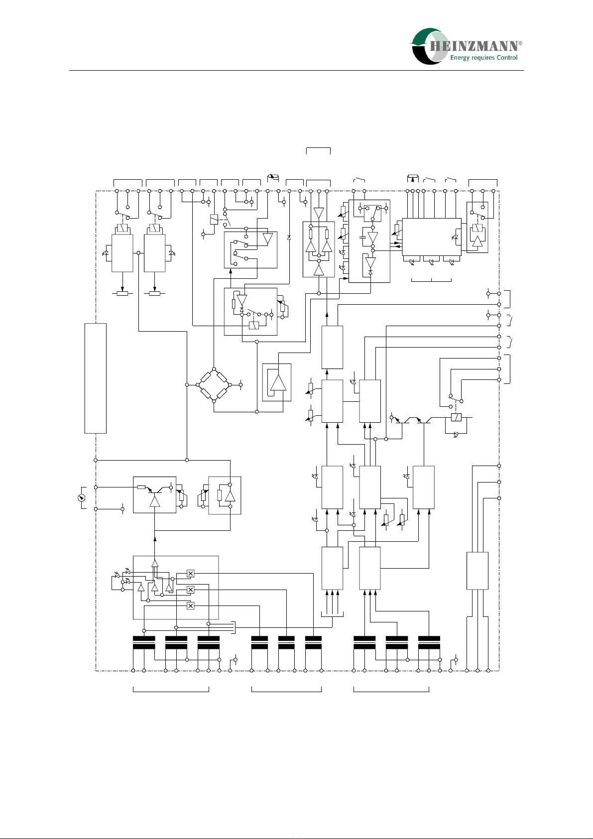
3Block Diagram
E
N
115
230
230
230
115
115
L1
L2
L3
Generator voltages
Analogue Theseus AT 01
1
2
14 16 13 54 55 56 37 38 35 36
52
53
51
28
27
30
29
25
24
23
32
31
4
6
39
5
40
20
21
12
11
9
8
42
41
44
43
46
47
45
49
50
48
18 17
33 34
15
Phase
rotaton
indicators
KW- meter
adjus.
Load share
line adjus.
Voltages
Voltages
Currents
Signal
processor
Signal
processor
Frequency
comparison
Phase angle
comparison
Phase
rotation o.k.
Insolated
supply
voltage
Angle
Delay
Rotation o.k.
in phase
Frequency
from bus
Frequency from
generator Frequencies
eaquel Gain Synchronizer time
Integrator Output
amplifier
Reset
circuit
locked
breaker
closed
+Synchron.
relay
-
+
0 V
Bridge
Generator
power
Reversed
power Reversed
power
Forward
power
0 V
+
0 V
0 V
0 V
Internal load
limitation
0 V
Control
logic
0 V 0 V
internal
base load
Base load on
Load
ramp
Max.
Min.
on/
off
up updown down
E
N
115
230
230
230
115
115
L1
L2
L3
Bus / mains
I1
I2
I3
Generator currents
0 V
+24 V
Supply
voltage
Synchronizer
relay
-10V0V+10V Sync.
on Relay
inhibit Group
sync.
Load at
minimum
Loadramp
on / off
Base load
on / off
External
Base load
Loadramp
up / down
Load sharing
0 V
Synchronizer
to governor
External load
limitation
Droop
Output
Loadshare line
Input
loadshare line
Generator
breaker
Mains
breaker
Forward power
relay
Reversed power
relay
Load control
unit
KW- indicator
Figure 1: Block Diagram of Analogue THESEUS AT 01

4 Mode of Operation
THESEUS Analogue AT 01 7
4Mode of Operation
4.1 General
Referring to the AT 01 block diagram, there are three sections incorporating load sharing,
synchronising and load ramping; these can be used independently of each other or in
combination.
The connection to the voltage and current inputs are made directly to the alternator outputs
and require a three wire, three phase signal with appropriate current transformer inputs
which can be specified to 1 A or 5 A CTs. The BUS voltage inputs on the secondary side
of the generator breaker are used for synchronising and a comparison is made between the
generator and the BUS frequencies and phases.
4.2 Load Measuring and Sharing Device
The three phase voltage inputs are conditioned and multiplied by the three phase current
inputs and are first compared for phase acceptance. LED’s indicate whether the phase of
the current to the voltage is correct. There is 180° reversing link for each current input that
can be changed when the engine is running, thus allowing easy reversal of current
transformers terminals K and L without shutting the generator down.
The load sharing device measures the output power of an AC generator (3 phase voltage
and current) and converts this to a DC voltage proportional to the generator load. This
voltage is connected to a bridge circuit. In parallel operation, these bridge circuits are
connected together by paralleling lines. If the power of the paralled generators are not
equal, there originates a little voltage difference between the bridges and then a small DC
current will flow in the paralleling leads. This will normaly cause a change in the speed
setting of the connected generators, but, as they are all coupled electrically by the rotary
field of the generators and have the same speed, their power output will be changed. When
the generators are sharing the total load correctly there will be no current in the paralleling
leads. This type of load sharing is very effective and can be accurate to within ±1% with
power factors between ±0.8.
The generator power proportional signal is also used for external meter indication and
forward/reverse power relay contacts. These contacts can be used for generator safety and
also starting and stopping generator sets, depending upon load level.

4 Mode of Operation
8THESEUS Analogue AT 01
4.3 Synchronizer Device
The auto synchronizer incorporates three phase voltage inputs which are conditioned and
compared for frequency and phase alignment. The unit first compares the frequency of the
BUS to the generator and gives an output signal to the governor speed that automatically
aligns the frequency. Once alignment is achieved, LED indication is given and the next
part of the circuit tries to align the phase. Once this is achieved, another LED confirms
alignment and an adjustable timer is then brought into operation before the breaker signal
is given. This delay time makes sure, that the generator breaker may be closed in constant
operating conditions only.
The device has a gain and a stability control for frequency and phase correction and also an
adjustable breaker delay and phase angle for optimum synchronisation time. The
synchronizer can normally close the breaker from diesel engine stop in approximately 8 -
12 seconds.
There is also a sync lock facility that allows the generator to be synchronised to a BUS, but
no breaker signal is given and is permanently synchronised in phase to a reference
frequency, ie, the BUS. This is very useful for checking phasing of transformers,
optimizing of parameters, etc, during commissioning or for stand-by synchronisation.
Under normal operation, once the breaker closure signal has been given, the unit is
automatically reset and disconnected from the governor after one second. Then the
synchronizer device is not controlling the speed of the engine anymore. Due to this fact,
there is no need for any interposing relay between the synchroniser and governor speed
input.
4.4 Load Ramp Device
The main function of the load ramp device is to soft load isochronously a single engine
after closure of the generator breaker.
The device can offer a standard load ramp from zero with adjustable time to rated load
equal to that of the paralleled engines offering a bumpless transfer and connection of load.
Isochronous unloading is also possible with a simple opening of a contact and the engine
will unload softly down to zero or a base load option which is internally or externally
adjustable. The time constants are adjustable seperatly.
There is also an enhanced feature of a minimum load relay which is set approximately to
3% of rated load which allows the generator breaker to be opened automatically once the
engine has ramped down to zero load. LED annunciation shows the state of the ramp
generator and relay functions.

5 Technical Data
THESEUS Analogue AT 01 9
5Technical Data
5.1 General
Input voltage 3 x 110 V or 415 V AC ±10%
phase to phase
Input current 0 - 5 A per phase max. 2 VA
or 0 - 1 A per phase max. 2 VA
select by resistor change
Current consuption 400 mA
Supply voltage 18 - 40 V DC 500 mA max.
Frequency range of generator 50/60 Hz
Temperature range 0 - 70° C
Protection grade IP 00
Weight 1.8 kg
5.2 Load Measuring and Sharing Device
Load measuring U x I x cosϕwith three phases
Load sharing up to 15 gensets in parallel
Output signal 6 V at 100% generator power,
adjustable
Output signal to kilowatt meter 0 - 1 V or 0 - 1 mA, adjustable
Forward power relay adjustable 0 - 80% load
indication with LED
contact load 30 V DC, 1 A
Reverse power relay adjustable from 20% power up to
30% reverse power
indication with LED
contact load 30 V DC, 1 A
Reverse power indication 1 LED per phase
Changeover of current transformer connections link changeover without shutting down
the engine
Load limitation internal or external adjustable, 0 - 100%
Generator breaker closure LED indication

5 Technical Data
10 THESEUS Analogue AT 01
Mains breaker closure LED indication
5.3 Synchronizer Device
Contact load of synchronizer relay 30 V DC, 2.5 A
Phase angle ±1 up to ±15°, adjustable
Synchronizer time 3 up to 15 sec. depends on plant,
adjustable
Gain adjustable
Output signal ±4 V
max. frequency correction ±2 Hz
Generator frequency o.k. LED indication
Bus frequency o.k. LED indication
Bus = generator frequency LED indication
Phase angle o.k. LED indication
Phase rotation o.k. LED indication
Synchronizer inhibit LED indication
Synchronizer relay closure LED indication
5.4 Load Ramp Device
Base load setting internal or external adjustable, 0 - 100%
Load ramp up ramptime adjustable, LED indication
Load ramp down ramptime adjustable, LED indication
Load at minimum relay
indication with LED
contact load 30 V DC, 1 A
Load at maximum indication with LED

6 Electrical Connection
THESEUS Analogue AT 01 11
6Electrical Connection
6.1 Table of Terminal Connections and their Functions
Terminal Function
1 0 V supply voltage
2 +24 V supply voltage
3 screen of lines on terminals 4, 5 and 6, 7
4 signal synchronizer output to governor
5 0 V synchronizer output to governor
6D signal load sharing output to digital governor
6A signal load sharing output to analogue governor
7 0 V load sharing output to governor
8 input signal of load share line
9 input 0 V of load share line
10 screen of load share lines
11 output 0 V of load share line
12 output signal of load share line
13 +10 V supply to load control unit and load setpoint potentiometer
14 -10 V supply to load control unit
15 output signal to load control unit
16 output 0 V to load control unit and load setpoint potentiometer
17 output signal to kilowatt meter, 0 - 5 V or 0 - 1 mA
18 output 0 V to kilowatt meter
19 0 V
20 input 0 V for droop
21 input signal for droop
22 screen of lines on terminals 23, 24 and 25
23 reference for external base load potentiometer
24 signal of external base load potentiometer
25 0 V for external base load potentiometer
26 0 V
27 switch input for load ramp close = on
28 0 V open = off

6 Electrical Connection
12 THESEUS Analogue AT 01
Terminal Function
29 switch input for base load close = on
30 0 V open = off
31 switch input to ramp up / down close = up
32 0 V open = down
33 switch input for synchronizer close = off
34 +12 V via 100 Ohm open = on
35 output for island / group synchronization
36 0 V
37 synchronizer relay inhibit close = inhibit
38 +12 V via 100 Ohm open = synch. possible
39 0 V 0 - 3 V or
40 external load limitation 10 kOhm potentiometer
41 0 V
42 generator breaker closed
43 0 V
44 mains breaker closed
45 Common forward power relay
46 N/C 30 V DC, 1.5 A
47 N/O
48 Common reverse power relay
49 N/C 30 V DC, 1.5 A
50 N/O
51 Common load at minimum relay
52 N/C 30 V DC, 1.5 A
53 N/O
54 Common synchronizer relay
55 N/C 30 V DC, 2.5 A
56 N/O

6 Electrical Connection
THESEUS Analogue AT 01 13
6.2 Connection of Bus Voltages and Current Transformers
AT 01
Generator
voltage
Earth
N
L1
L2
L3
Earth
N
L1
L2
L3
L3
L3
L2
L2
L1
L1
Bus
voltage
Generator
current
N
L1
L2
L3
Generator
PE
Bus
L1 L2 L3
NPE
Generator
breaker
Attention:
Take care that the right connections are made to
the high voltage phases on the AT 01!
The connections are shown as a generator power control with
synchronizer application.
When the unit is used as a group synchronizer and for controlled mains supply
a) the generator terminals are replaced by the island group (bus bar),
b) the bus bar terminals are replaced by the mains and
c) the generator breaker is replaced by the mains breaker.
Figure 2: Connection of Bus Voltages and Current Transformers

6 Electrical Connection
14 THESEUS Analogue AT 01
6.3 Connection with Control Unit of Series E 1 - F and E 2 - F
AT 01 KG 1-F/KG 2-F
456
LMG
0V
SyG
white
brown
blue
Accessory
Plug
Terminal
Strip
Cable 3 x 0,5 mm² with shielding
max. lenght 50 m
Shielding connected at control unit only
Figure 3: Connection with Control Unit of Series E 1 - F and E 2 - F
6.4 Connection with Control Unit of Series E 6 up to E 40
AT 01
LMG
0V
SyG
A3
KG 6 up to KG 40
Accessory
Plug
Terminal
Strip
456 B3E3
Cable 3 x 0,5 mm² with shielding
max. lenght 50 m
Shielding connected at control unit only
Figure 4: Connection with Control Unit of Series E 6 up to E 40
Table of contents
Other Heinzmann Recording Equipment manuals


