Evco Vgraph User manual

Evco S.p.A. Vgraph | Hardware manual ver. 1.01 | Code 114VGRAHWE01
page 1 of 22
Vgraph
CANBUS USER INTERFACE WITH
LCD GRAPHIC DISPLAY
ENGLISH
HARDWARE MANUAL ver. 1.01
CODE 114VGRAHWE01

Evco S.p.A. Vgraph | Hardware manual ver. 1.01 | Code 114VGRAHWE01
page 2 of 22
Important
Important
Read these instructions carefully before installing and using the instrument and follow all additional information for installation and electrical
connection; keep these instructions close to the interface for future consultations.
The interface must be disposed according to the local legislation about the collection for electrical and electronic equipment.

Evco S.p.A. Vgraph | Hardware manual ver. 1.01 | Code 114VGRAHWE01
page 3 of 22
Index
1.
INTRODUCTION ......................................................................................................................................................................................... 4
1.1.
Introduction.................................................................................................................................................................................................... 4
1.2.
Available models for the programmable controllers of the family c-pro........................................................................................................ 5
1.3.
Available models for the programmable controllers of the family c-pro 3..................................................................................................... 5
2.
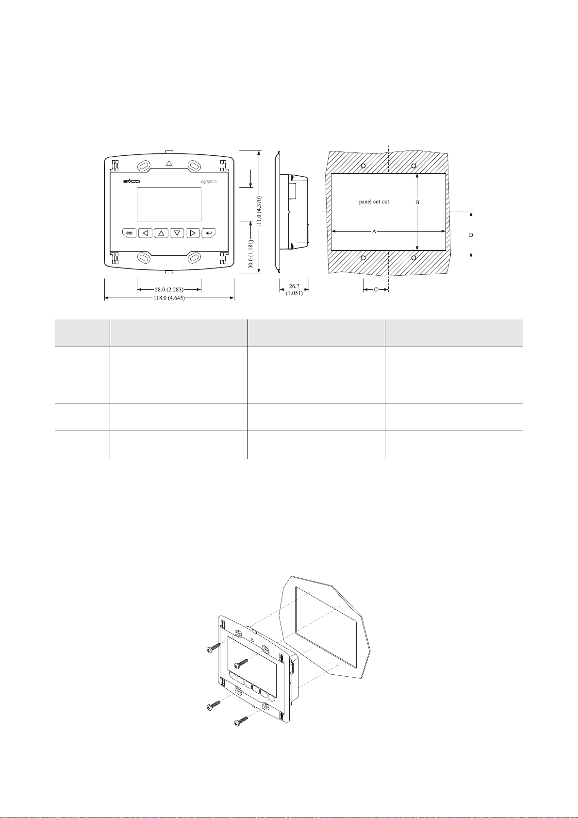
SIZE AND INSTALLATION........................................................................................................................................................................ 6
2.1.
Size ................................................................................................................................................................................................................ 6
2.2.
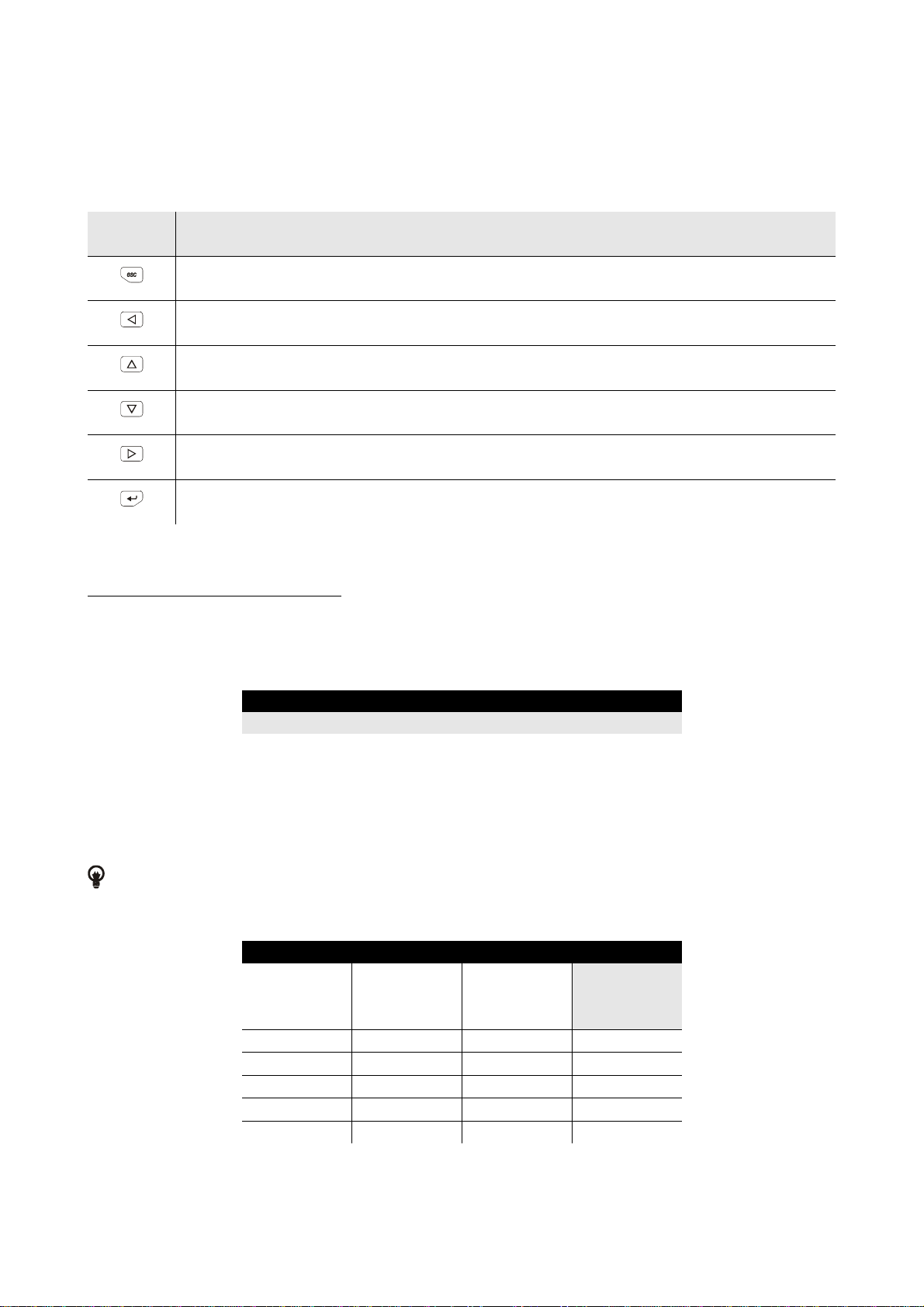
Installation ..................................................................................................................................................................................................... 6
2.3.
Additional information for installation........................................................................................................................................................... 7
3.
ELECTRICAL CONNECTION..................................................................................................................................................................... 8
3.1.
Electrical connection...................................................................................................................................................................................... 8
3.2.
Additional information for electrical connection............................................................................................................................................ 9
4.
CONFIGURATION..................................................................................................................................................................................... 10
4.1.
Preliminary information............................................................................................................................................................................... 10
4.2.
Configuring the interface ............................................................................................................................................................................. 10
4.3.
List of configuration parameters .................................................................................................................................................................. 11
4.4.
Configuring a device through the interface.................................................................................................................................................. 14
5.
SIGNALS..................................................................................................................................................................................................... 15
5.1.
Signals.......................................................................................................................................................................................................... 15
6.
ACCESSORIES........................................................................................................................................................................................... 16
6.1.
Frontal plates CPVP* by Evco..................................................................................................................................................................... 16
1.1.1.
Available models.................................................................................................................................................................................... 16
1.1.2.
Size ........................................................................................................................................................................................................ 16
6.2.
Support for wall mounting CPVW00........................................................................................................................................................... 16
1.1.3.
Available models.................................................................................................................................................................................... 16
1.1.4.
Size ........................................................................................................................................................................................................ 17
6.3.
Gasket 0027000007...................................................................................................................................................................................... 17
1.1.5.
Available models.................................................................................................................................................................................... 17
1.1.6.
Size ........................................................................................................................................................................................................ 17
7.
TECHNICAL DATA................................................................................................................................................................................... 18
7.1.
Technical data.............................................................................................................................................................................................. 18

Evco S.p.A. Vgraph | Hardware manual ver. 1.01 | Code 114VGRAHWE01
page 4 of 22
1. INTRODUCTION
1.1. Introduction
Vgraph is a new and innovative user interface for the programmable controllers of the family c-pro that support the CAN bus and for the
programmable controllers of the family c-pro 3.
The main features of the interface are the possibility to communicate to the user a great deal of information and the remarkable ease of control; these
features are due to the use of a 128 x 64 pixel single colour LCD graphic display (black with rearlighting through white LED), to the 6 buttons (with
preset functions) membrane keyboard and to the CAN bus (for the connection to the controllers).
This last also allows the use of the interface in multimaster networks.
Thanks to its constructive features, Vgraph offers several mounting typologies; this is possible:
- by panel, at the front of units, of machines for refrigeration or for air conditioning, of electrical panels and as well as in all those
applications where a frontal protection degree IP65 is required
- built-in by wall, in traditional box (like "506" by BTicino)
- by wall, on the support CPVW00 by Evco (to order separately).
Also the necessity to customize the interface, in order to integrate it aesthetically in residential and commercial environments, is satisfied by Vgraph
since at the front of the interface one can apply both the plates CPVP* by Evco (to order separately, made in plastic material and available in two
different colorations, white and black) and the numerous plates series "Living" and "Light" by BTicino.
By request, Vgraph can be supplied with:
- real time clock
- alarm buzzer.

Evco S.p.A. Vgraph | Hardware manual ver. 1.01 | Code 114VGRAHWE01
page 5 of 22
1.2. Available models for the programmable controllers of the family c-pro
The following table shows the available models and the respective main features.
Code Main features
CPV3L2C4NX Not isolated power supply 24 VAC or 20 ... 40 VDC, 128 x 64 pixel LCD graphic display
CPV3L2C4 Not isolated power supply 24 VAC or 20 ... 40 VDC, 128 x 64 pixel LCD graphic display, real time
clock, alarm buzzer
CPV3L2C7NX Isolated power supply 12-24 VAC or 15 ... 40 VDC, 128 x 64 pixel LCD graphic display
CPV3L2C7 Isolated power supply 12-24 VAC or 15 ... 40 VDC, 128 x 64 pixel LCD graphic display, real time
clock, alarm buzzer
1.3. Available models for the programmable controllers of the family c-pro 3
The following table shows the available models and the respective main features.
Code Main features
EPV4GBR Not isolated power supply 24 VAC or 20 ... 40 VDC, 128 x 64 pixel LCD graphic display, real time
clock, alarm buzzer
EPV3GBR Isolated power supply 12-24 VAC or 15 ... 40 VDC, 128 x 64 pixel LCD graphic display, real time
clock, alarm buzzer

Evco S.p.A. Vgraph | Hardware manual ver. 1.01 | Code 114VGRAHWE01
page 6 of 22
2. SIZE AND INSTALLATION
2.1. Size
Size in mm (in).
Size Minimum Typical Maximum
A 104.0 (4.094) 104.0 (4.094) 104.8 (4.125)
B 70.0 (2.755) 70.0 (2.755) 70.8 (2.787)
C 22.0 (0.866) 23.0 (0.905) 24.0 (0.944)
D 40.8 (1.606) 41.8 (1.645) 42.8 (1.685)
2.2. Installation
The installation is possible:
- by panel
- built-in by wall, in traditional box (like "506" by BTicino)
- by wall, on the support CPVW00 by Evco (to order separately); look at chapter 6 (ACCESSORIES).
The following drawing shows the installation by panel, with 4 screws (supplied by the builder).

Evco S.p.A. Vgraph | Hardware manual ver. 1.01 | Code 114VGRAHWE01
page 7 of 22
At the front of the interface one can apply the plates CPVP* by Evco (to order separately, made in plastic material and available in two different
colorations, white and black); look at chapter 6 (ACCESSORIES).
2.3. Additional information for installation
- working conditions (working temperature, humidity, etc.) must be between the limits indicated in the technical data
- do not install the interface close to heating sources (heaters, hot air ducts, etc.), devices provided with big magnetos (big speakers, etc.),
locations subject to direct sunlight, rain, humidity, dust, mechanical vibrations or bumps
- according to the safety legislation, the protection against electrical parts must be ensured by a correct installation of the interface; the parts
that ensure the protection must be installed so that you can not remove them if not by using a tool.

Evco S.p.A. Vgraph | Hardware manual ver. 1.01 | Code 114VGRAHWE01
page 8 of 22
3. ELECTRICAL CONNECTION
3.1. Electrical connection
Position micro-switch 4 on position ON to plug in the termination of the CAN port; micro-switches 1, 2 and 3 are reserved.
The following tables show the meaning of the connectors.
Connector 1: CAN port.
Terminal Meaning
1 ground
2 signal +
3 signal -
The maximum length of the connecting cables of the CAN port of the interface depends on the baud rate of the CAN communication, as
follows:
- 1,000 m (3,280 ft) with baud rate 20,000 baud
- 500 m (1,640 ft) with baud rate 50,000 baud
- 250 m (820 ft) with baud rate 125,000 baud
- 50 m (164 ft) with baud rate 500,000 baud.
Connect the CAN port of the interface using a twisted pair.
According to the default settings, the interface recognizes the baud rate automatically, on condition that it is one of the those mentioned above;
hereinafter one suggests setting the same baud rate of the others devices in the network.
Connector 2: power supply (not isolated 24 VAC or 20 ... 40 VDC or isolated 12-24 VAC or 15 ... 40 VDC, according to the model).
Terminal Meaning
4 power supply
5 power supply

Evco S.p.A. Vgraph | Hardware manual ver. 1.01 | Code 114VGRAHWE01
page 9 of 22
The maximum length of the connecting cables of the power supply is 10 m (32.8 ft).
In the models with not isolated power supply, this must galvanically be isolated from the one of the other devices connected in the
network.
3.2. Additional information for electrical connection
- do not operate on the terminal blocks with electrical or pneumatic screwers
- if the interface has been moved from a cold location to a warm one, the humidity could condense on the inside; wait about an hour before
supplying it
- test the working power supply voltage, working electrical frequency and working electrical power of the interface; they must correspond
with the local power supply
- disconnect the local power supply before servicing the interface
- do not use the interface as safety device
- for repairs and information on the interface please contact Evco sales network.

Evco S.p.A. Vgraph | Hardware manual ver. 1.01 | Code 114VGRAHWE01
page 10 of 22
4. CONFIGURATION
4.1. Preliminary information
The following table shows the main meaning of the buttons.
Button Meaning
button escape (hereinafter called “button ESC”)
button move to left (hereinafter called “button LEFT”)
button increase (hereinafter called “button UP”)
button decrease (hereinafter called “button DOWN”)
button move to right (hereinafter called “button RIGHT”)
button confirm (hereinafter called “button ENTER”)
4.2. Configuring the interface
To gain access to the procedure operate as follows:
1. Switch off the power supply.
2. Keep pressed buttons ESC and RIGHT.
3. Switch on the power supply.
4. When the display shows the following menu (hereinafter called Main menu) release buttons ESC and RIGHT:
V-Graph
Parameters
Contrast
CAN Network
Modbus
Info
Real date and time
It is also possible to show the Main menu operating as follows:
5. Make sure the power supply is switched on.
6. Keep pressed 2 s buttons LEFT and ENTER: the display will show the following menù (hereinafter called Network Status menu):
Network Status
Loc 99 OK
> >
(back to the
Main menu)
1 1 - > >
2 0 - > >
3 0 - > >
4 0 - > >
5 0 - > >
7. Press and release button ENTER: the display will show the Main menu.

Evco S.p.A. Vgraph | Hardware manual ver. 1.01 | Code 114VGRAHWE01
page 11 of 22
To gain access a submenu operate as follows:
8. From step 4, press and release button UP or button DOWN to select the submenu.
9. Press and release button ENTER.
The access to the CAN Network submenu is protected by password.
To gain access to the CAN Network submenu operate as follows:
10. From step 4, press and release button UP or button DOWN to select the submenu CAN Network.
11. Press and release button ENTER.
12. Press and release again button ENTER.
13. Press and release over and over again button DOWN to set “-19”.
14. Press and release button ENTER.
To modify a configuration parameter belonging to the Parameters submenu, to the CAN Network submenu or to the Modbus submenu operate as
follows:
15. From step 9, press and release button UP or button DOWN to select the parameter.
16. Press and release button ENTER.
17. Press and release button UP or button DOWN to modify the value.
18. Press and release button ENTER to confirm the value.
19. Press and release button ESC to go back to the Main menu.
To modify the display’s contrast operate as follows:
20. From step 4, press and release button UP or button DOWN to select the Contrast submenu.
21. Press and release button ENTER.
22. Press and release button UP or button DOWN to modify the value.
23. Press and release button ENTER to confirm the value.
24. Press and release button ESC to go back to the Main menu.
To modify the real date and time:
25. From step 4, press and release button UP or button DOWN to select the item Real date and time.
26. Press and release button ENTER.
27. Press and release button UP or button DOWN to modify the value.
28. Press and release button ENTER or button RIGHT to confirm the value and modify the following field.
29. Repeat steps 26 and 27.
30. Press and release button ESC to go back to the Main menu.
To quit the procedure:
31. Press and release over and over again button ESC: possible modifications will not be saved.
Switch off the power supply and then switch it on after the modification of the configuration.
4.3. List of configuration parameters
Submenu Parameter Min. Max. Unit Default Description
Parameters DateCharSep - - - - - - - - - / Date separator (ASCII character)
Parameters Year format - - - - - - - - - YY
Year format
YY = two numbers (for example 10)
YYYY = four numbers (for example 2010)

Evco S.p.A. Vgraph | Hardware manual ver. 1.01 | Code 114VGRAHWE01
page 12 of 22
Parameters Date format - - - - - - - - - dmy
Date format
ymd = year, month and day
mdy = month, day and year
dmy = day, month and year
Parameters TimeCharSep - - - - - - - - - : Time separator (ASCII character)
Parameters TimeWithSec 0 1 - - - 1 Showing the seconds in the real time
1 = yes
Parameters Time AM/PM 0 1 - - - 0
Time format
0 = 24 h (for example 15:20)
1 = 12 h (for example 3:20 PM)
Parameters Back Mode - - - - - - - - - TIME
Backlight mode
OFF = backlight is never lit
ON = backlight is always lit
TIME = backlight is lit the time one has
set with parameter BackTimeout
since the last operation with the
buttons
Parameters BackTimeout 0 240 s 60 Backlight duration (only if parameter Back Mode
has value TIME)
Parameters I/O Timeout 0 240 s 60
Local (or of the interface) CAN communication
time-out (after this time without CAN
communication, the display will show
Checking . . . and the l’I/O of the interface will
be disabled)
Parameters PW Timeout 0 240 s 60
CAN Network submenu access password
time-out (after this time without one has operated
with the buttons, to gain access again to the
submenu one has to set the password again)
Parameters Contrast 0 63 - - - 25 Display’s contrast
Parameters Buzz On Key 0 1 - - - 1 Uttering a beep while pressing a button
1 = yes
Parameters PrintLoad. 0 1 - - - 0
Showing the indication Loading . . . while
loading a page
1 = yes
Parameters Print Frame 0 1 - - - 0 Showing frames instead small size pages
1 = yes

Evco S.p.A. Vgraph | Hardware manual ver. 1.01 | Code 114VGRAHWE01
page 13 of 22
CAN Network MyNode 1 127 - - - 99 Local (or of the interface) CAN node’s address
CAN Network Master - - - - - - - - - YES The interface always works as master
CAN Network Baud - - - - - - - - - Auto
CAN communication baud rate
20K = 20,000 baud
50K = 50,000 baud
125K = 125,000 baud
500K = 500.000 baud
Auto = the interface recognizes the baud
rate automatically, on condition
that it is one of the those
mentioned above
One suggests modifying the value of the
parameter and assign each device in the network
the same baud rate.
CAN Network Net Timeout 1 240 s 5
Remote (or of the devices in the network) CAN
communication time-out (after this time without
CAN communication with a device, this will be
excluded by the network)
CAN Network NW Node [1] 1 [32] 127 - - - - - -
Remote (or of the devices in the network) CAN
nodes’ address; example for [1] 2:
[1] = node
2= node’s address
Modbus Address 1 247 - - - 1 Modbus address (reserved)
Modbus Parity - - - - - - - - - even
Modbus communication parity (reserved)
none = no parity
odd = odd
even = even
Modbus Baudrate - - - - - - - - - 9600
Modbus communication baud rate (reserved)
1200 = 1,200 baud
2400 = 2,400 baud
4800 = 4,800 baud
9600 = 9,600 baud
19200 = 19,200 baud
28800 = 28,800 baud
38400 = 38,400 baud
57600 = 57,600 baud
Modbus Bit Stop - - - - - - - - - 1 bit Modbus communication stop bit number
(reserved)

Evco S.p.A. Vgraph | Hardware manual ver. 1.01 | Code 114VGRAHWE01
page 14 of 22
4.4. Configuring a device through the interface
Operate as follows:
1. Switch off the power supply of the device and of the interface.
2. Connect the device to the interface through the CAN port; look at chapter 3 (ELECTRICAL CONNECTION).
3. Switch on the power supply of the device and of the interface.
4. Operate on the interface to set parameter NW Node; look at chapter 4 (CONFIGURATION).
Parameter NW Node belongs to the CAN Network submenu.
According to the default settings, the CAN node’s address of a controller has value 1(so operate on the interface to set parameter
NW Node to [1] 1) and the CAN node’s address of an expansion has value 2(so operate on the interface to set parameter
NW Node to [2] 2).
5. Keep pressed 2 s buttons LEFT and ENTER of the interface: the display will show the Network Status menu:
Network Status
Loc 99 OK > >
1 1 OK > >
2 2 OK > >
3 0 - > >
4 0 - > >
5 0 - > >
6. Press and release button UP or button DOWN to select the device.
7. Press and release button ENTER: the display will show the device’s Main menu.
8. Operate as indicated in paragraph 4.2 (Configuring the interface).
Switch off the power supply of the device and then switch it on after the modification of the configuration.

Evco S.p.A. Vgraph | Hardware manual ver. 1.01 | Code 114VGRAHWE01
page 15 of 22
5. SIGNALS
5.1. Signals
The following table shows the meaning of the LEDS at the back of the interface.
LED Meaning
POWER if it is lit, the interface will be turned supplied
CAN
RX it provides information on the status of the receiving line of the CAN port
CAN
TX it provides information on the status of the transmitting line of the CAN port

Evco S.p.A. Vgraph | Hardware manual ver. 1.01 | Code 114VGRAHWE01
page 16 of 22
6. ACCESSORIES
6.1. Frontal plates CPVP* by Evco
1.1.1. Available models
The following table shows the available models and the respective main features.
Code Main features
CPVP00 plastic material, white
CPVP01 plastic material, black
1.1.2. Size
Size in mm (in).
6.2. Support for wall mounting CPVW00
1.1.3. Available models
The following table shows the available models and the respective main features.
Code Main features
CPVW00 plastic material, white

Evco S.p.A. Vgraph | Hardware manual ver. 1.01 | Code 114VGRAHWE01
page 17 of 22
1.1.4. Size
Size in mm (in).
6.3. Gasket 0027000007
1.1.5. Available models
The following table shows the available models and the respective main features.
Code Main features
0027000007 black, to get a frontal protection degree IP65 (only in case of panel mounting)
1.1.6. Size
Size in mm (in).

Evco S.p.A. Vgraph | Hardware manual ver. 1.01 | Code 114VGRAHWE01
page 18 of 22
7. TECHNICAL DATA
7.1. Technical data
Purpose of control: user interface for programmable controllers.
Construction of control: electronic device to be incorporated.
Box: self-extinguishing transparent.
Size: 118.0 x 111.0 x 26.7 mm (4.645 x 4.370 x 1.051 in).
Size refers to the interface with connector 1 and connector 2 properly plugged.
Installation:
the installation is possible:
- by panel
- built-in by wall, in traditional box (like "506" by BTicino)
- by wall, on the support CPVW00 by Evco (to order separately); look at chapter
6 (ACCESSORIES).
Fixing screws are always supplied by the builder.
At the front of the interface one can apply the plates CPVP* by Evco (to order separately, made in
plastic material and available in two different colorations, white and black); look at chapter
6 (ACCESSORIES).
Frontal protection degree: IP40 (IP65 for panel mounting with gasket 0027000007, to order separately); look at chapter
6 (ACCESSORIES).
Connections:
extractable male + female terminal blocks (power supply and CAN port), 6 poles telephone connector
(programming port).
The maximum length of the connecting cables of the CAN port of the interface depends on the baud
rate of the CAN communication, as follows:
- 1,000 m (3,280 ft) with baud rate 20,000 baud
- 500 m (1,640 ft) with baud rate 50,000 baud
- 250 m (820 ft) with baud rate 125,000 baud
- 50 m (164 ft) with baud rate 500,000 baud.
According to the default settings, the interface recognizes the baud rate automatically, on condition
that it is one of the those mentioned above.
Working temperature: from 0 to 55 °C (32 to 131 °F, 10 ... 90% of relative humidity without condensate).
Pollution situation: 2 or more.

Evco S.p.A. Vgraph | Hardware manual ver. 1.01 | Code 114VGRAHWE01
page 19 of 22
Power supply:
according to the model:
- 12-24 VAC, 50/60 Hz, 3 VA isolated or 15 ... 40 VDC isolated
- 24 VAC, 50/60 Hz, 3 VA not isolated or 20 ... 40 VDC not isolated
supplied from a class 2 circuit.
The maximum length of the connecting cables of the power supply is 10 m (32.8 ft).
In the models with not isolated power supply, this must galvanically be isolated from the one of the
other devices connected in the network.
Protect the power supply with an UL listed or recognized fuse rated:
- 80 mA-T if the user interface is powered with 15... 40 VDC
- 160 mA-T if the user interface is powered with 12... 19 VAC
- 125 mA-T if the user interface is powered with 19... 24 VAC.
Overvoltage category: III.
Real time clock data maintenance in
absence of power supply: 2 days will battery fully charged; the real time clock is available by request.
Battery charging time 2 min without interruptions (the battery is charged by the power supply of the interface).
Alarm buzzer: by request.
Display: 128 x 64 pixel single colour LCD graphic display (black with rearlighting through white LED).
Communication ports:
2 ports:
- 1 non optoisolated CAN port
- 1 programming port.

Evco S.p.A. Vgraph | Hardware manual ver. 1.01 | Code 114VGRAHWE01
page 20 of 22
Notes
________________________________________________________________________________________________________________________
________________________________________________________________________________________________________________________
________________________________________________________________________________________________________________________
________________________________________________________________________________________________________________________
________________________________________________________________________________________________________________________
________________________________________________________________________________________________________________________
________________________________________________________________________________________________________________________
________________________________________________________________________________________________________________________
________________________________________________________________________________________________________________________
________________________________________________________________________________________________________________________
________________________________________________________________________________________________________________________
________________________________________________________________________________________________________________________
________________________________________________________________________________________________________________________
________________________________________________________________________________________________________________________
________________________________________________________________________________________________________________________
________________________________________________________________________________________________________________________
________________________________________________________________________________________________________________________
________________________________________________________________________________________________________________________
________________________________________________________________________________________________________________________
________________________________________________________________________________________________________________________
________________________________________________________________________________________________________________________
________________________________________________________________________________________________________________________
________________________________________________________________________________________________________________________
________________________________________________________________________________________________________________________
________________________________________________________________________________________________________________________
Table of contents
Other Evco Recording Equipment manuals