Bitzer Group Lodam LMC341 DIWE User manual
Lodam Condensing Unit Controller
Modbus Interface
Version 2.0
LMC341 DIWE

Page 2
Contents
1. Read this first ................................................................................................ 4
1.1. Installation ........................................................................................ 4
1.2. Safety............................................................................................... 4
2. General ......................................................................................................... 5
3. Definitions..................................................................................................... 5
4. How to ... ...................................................................................................... 6
4.1. Connection samples......................................................................... 6
4.2. Communication recommendations.................................................. 6
5. Connections.................................................................................................. 7
5.1. Connections on the LMC341 DIWE controller..................................... 7
5.2. Cable specification .......................................................................... 7
5.3. Configuration................................................................................... 7
5.4. RS485 Repeater .............................................................................. 7
5.5. Recommended guidelines for cable routing. . . . . . . . . . . . . . . . . . . . . . . . . . . . . . . . . . . . . . 8
6. Setup ............................................................................................................ 8
6.1. Modbus configuration....................................................................... 8
6.2. Data values, scaling and data types ................................................. 9
6.3. Modbus function codes ................................................................... 9
6.4. Modbus exception codes ................................................................. 9
7. Functions....................................................................................................... 10
7.1. Status information ............................................................................ 10
7.2. Inputs............................................................................................... 11
7.3. Outputs ........................................................................................... 12
7.4. Alarms ............................................................................................. 13
7.5. Control............................................................................................. 15
7.6. Modbus sample communication ...................................................... 16
8. Standards ..................................................................................................... 16
9. Trouble shooting ........................................................................................... 17
10. Index ........................................................................................................... 18
11. Notes............................................................................................................ 19

Modbus Interface manual LMC341 DIWE
Page 3

Page 4
1. Read this first
The contents of this manual are subject to change
without notice.
Lodam electronics holds the copyright to this user’s
manual. The user must follow any instructions given in this
user manual entirely and not only partly. Any non-follow-
ing of this user manual result in exclusion of all warranties,
guarantees, and liabilities.
Copyright© 2013 by Lodam electronics a/s. All Rights
Reserved.
Disposing of the parts of the controller:
INFORMATION FOR USERS ON THE COR-
RECT HANDLING OF WASTE ELECTRICAL
AND ELECTRONIC EQUIPMENT (WEEE)
In reference to European Union directive 2012/19/EU and
the related national legislation, please note that:
1. WEEE cannot be disposed of as municipal waste and
such waste must be collected and disposed of sepa-
rately;
2. The public or private waste collection systems defined
by local legislation must be used. In addition, the equip-
ment can be returned to the distributor at the end of its
working life when buying new equipment;
3. The equipment may contain hazardous substances:
the improper use or incorrect disposal of such may
have negative eects on human health and on the
environment;
4. The symbol (crossed-out wheeled bin) shown on the
product or on the packaging and on the instruction
sheet indicates that the equipment must be disposed
of separately;
5. In the event of illegal disposal of electrical and elec-
tronic waste, the penalties are specified by local waste
disposal legislation.
1.1. Installation
Before installation, the user should be thoroughly
familiarized with this technical manual, especially
with purposes, installation, settings and operation.
Special care should be taken when installing and con-
necting external equipment (sensor, high voltage etc.)
and handling the PCB’s correctly according to protection
against ESD.
Installation of the LMC341 DIWE Condensing Unit Control-
ler must be performed by authorized personnel only. All
warranties are excluded in case installation is performed
by unauthorized personnel or in case the LMC341 DIWE has
not been correctly installed.
Electrical plant failures are to be immediately solved, even
though no immediate danger exists; the LMC341 DIWE
must not be operating.
1.2. Safety
The LMC341 DIWE is not a safety component and
cannot be used in “medical” or “life support”
equipment.
The LMC341 DIWE is not a safety component according to
the Machinery Directive.
Before commissioning, the service technician shall ensure
that personal safety requirements are met in conformity
with the Machinery Directive based on safety estimations.
The LDH105 should not be apart when operating.
Fuses can only be replaced and NOT left out.
Operation sta must in detail be informed about operating
the LMC341 DIWE before operating the LMC341 DIWE.
Only use recommended parts/spare parts on the LMC341
DIWE. All warranties are excluded in case unoriginal part/
spare parts are installed.

Modbus Interface manual LMC341 DIWE
Page 5
2. General
Lodam’s Condensing Unit Controller, LMC341 DIWE enable
you to gain total control of your condensing unit to deliver
cooling to one or more evaporators – thereby optimizing
your system to save energy, time and money.
Remote control of the controller is via Modbus over a
RS485 connection and this document describes the
settings for this.
3. Definitions
BEST BEST software
HW Hardware/electronics
LMT Lodam Multi Tool (PC communication
tool for Lodam controllers)
Modbus Application-layer messaging protocol -
http://www.modbus.org/specs.php
RS485 Hardware communication standard
Page 6
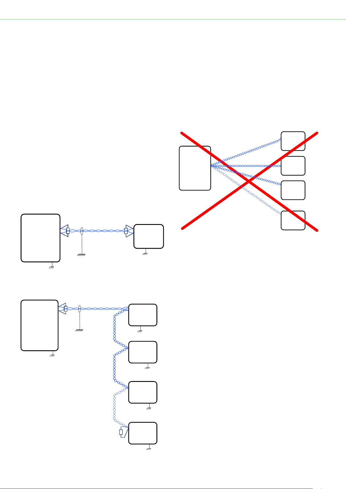
The end points, first and last controller on the string must
have a 120 ohm termination resistor.
All LMC341 DIWE controllers are grounded, the signal
ground is not needed as PE (Protective Earth) is used as
signal ground.
The following installation is not guaranteed to work!
Master
Controller
LMC341
DIWE
LMC341
DIWE
Modbus (RTU) via RS485
LMC341
DIWE
LMC341
DIWE
#1
#2
#3
#10
...
4.2. Communication recommen-
dations
The poll-interval setting in the master controller must be
considered. The processor of the LMC341 DIWE controller
can only handle a certain amount of requests per second.
Beyound this, request from the master controller will be
lost.
The data in the LMC341 DIWE controller don’t change very
rapidly so a poll interval of seconds will be sucient for
the monitoring purpose.
4. How to ...
4.1. Connection samples
• The Modbus communication is connected using a
shielded, 2-wired, twisted pair cable (RS485).The two
signal wires must be in the same pair of wires.
• The connection can be multi-drop with up to 10
LMC341 DIWE controllers on the same communication
line. For larger installations or from building to building, a
RS-485 repeater with galvanic isolation must be used.
• The cable must be installed as a string, not a star.
• The LMC341 DIWE is always the client (slave unit).
One master controller and one LMC341 DIWE.
Master
Controller
LMC341
DIWE
Modbus (RTU) via RS485 (2-wire)
120 ohm
Termination
resistor
120 ohm
Termination
resistor
One master controller and several LMC341 DIWE.
Master
Controller
LMC341
DIWE
LMC341
DIWE
Modbus (RTU) via RS485 (2-wire)
LMC341
DIWE
LMC341
DIWE
120 ohm
Termination
resistor
120 ohm
Termination
resistor
#1
#2
#3
#10
...

Modbus Interface manual LMC341 DIWE
Page 7
5. Connections
All LMC341 DIWE controllers have internally connected
signal ground and protective earth. The signal ground is
hence not needed as protective earth is used as signal
ground.
5.1. Connections on the LMC341
DIWE controller
Ethernet
2 x USB Host
RS485
1
2
3
4
+12V
Data+
Data-
GND
Data+
Modbus (RTU)
Data-
1 2 3 4
Terminal Description
CN32 - RS485 Modbus connection
GND: Do not use as all LMC341 DIWE controllers are
grounded(1).
Protective earth is used as signal ground.
Data- Inverted signal
Data+ Signal
+12V Power supply for RS485 connection.
Not used for Modbus communication!
Note (1): The LMC341 DIWE controller has internally
connected signal ground to PE (Protective Earth).
5.2. Cable specification
Communication is half duplex.
• Use shielded, tinned copper, twisted-pair cable – twisted
all the way to the controllers.
• Max 200 m cable length. Characteristic impedance
between 100 Ohm and 130 Ohm
• Foil or braided shield – shield grounded at the master
controller
• Shunt capacitance < 100 pF/m, AWG24, 2 * 120 Ohm
termination.
• Receiver impedance >= 12 kOhm.
5.3. Configuration
There can be up to 10 LMC341 DIWE controllers on the
same Modbus string.
If other equipment than LMC341 DIWE controllers are con-
nected on the same string, the maximum current sourcing
of the other equipment must be observed!
The network should be configured in sections, possible with
RS 485 repeaters between sections in large installations
and when connecting dierent buildings in one network. Up
to 3 repeaters may be used.
5.4. RS485 Repeater
The repeater should be an isolated (galvaniccally isolated)
RS485 repeater to separate the sections of the network.
The following products have been tested and verified to
work right out of the box:
• ICP CON 7510AR
• ICP CON 7510A
• Moxa TCC-120/120I
• BLACK BOX ICD202A
Other RS485 repeater brands and models should be tested
and verified before use in installations.

Page 8
5.5. Recommended guidelines for
cable routing
• Signal, control and communication cables should be
shielded with braided shielding and the shield connected
to the earth connection – preferrable at the master
controller.
• Signal, control and communication cables should
be routed so the influence from the power cables is
minimized. When crossing power cables, an 90 degrees
angle should be achieved
• Signal and power cables that run in parallel should be
separated by the largest possible appropriate clearance
distance, approx. 20 – 25 cm. A grounded shield plate or
grounded metal duct can be used instead.
• The cable shielding must not be interrupted.
• The cables should be kept as short as possible.
Route cables using grounded, metal cable trays or cable
ducts. Sections of cable tray or ducts must be connected
together with as large areas as possible.
• Communication cables should be twisted pair for the
data wires.
6. Setup
Communication with the LMC341 DIWE is via Modbus
(RTU). Configuration and reading of settings and readings
from the LMC341 DIWE is described in the following
sections.
Client Server
Initiate request
Perform the action.
Initiate the response
Receive the
response
Function code Data Request
Function code Data Response
6.1. Modbus configuration
Specification of the protocol:
Protocol:
Modbus (RTU mode)
See http://www.modbus.org/specs.php
Modbus node address:
LMC341 DIWE uses default address 1; can be
changed on the LUP200 display (option)
Baud rate:
Default 115200; 4800, 9600, 19200, 38400,
57600 are selectable
Number of data bits:
8
Parity:
Default Even; None and Odd parity are selectable
Number of stop bits:
Default 1; 2 (2 only if Parity is None)
Packet size:
Maximum 32 register in a row
Settings are configured on the LUP200 display of the
LMC341 DIWE controller in the Service->LOM MB config
menu.
Please observe that register numbers used in this manual
are zero-based as the LMC341 DIWE uses PDU telegrams.

Modbus Interface manual LMC341 DIWE
Page 9
6.2. Data values, scaling and data
types
Following is a description of used scaling and data types.
Scale 1, 10 and 100 refers to where the decimal point
is implied, as a decimal value can’t be transmitted via
Modbus.
Scale 1: The value is the exact value
Scale 10: To transmit a value it must be multiplied
by 10; i.e. 12.3 -> 123
A received value must be divided by 10;
i.e. 123 -> 12.3
Scale 100: To transmit a value it must be multiplied
by 100; i.e. 1.23 -> 123
A received value must be divided by 100;
i.e. 123 -> 1.23
uint8: Unsigned 8-bit integer
uint16: Unsigned 16-bit integer
sint16: Signed 16-bit integer
uint32: Unsigned 32-bit integer
sint32: Signed 32-bit integer
6.3. Modbus function codes
Function Code
(hexadecimal)
Code
(decimal)
Read Holding Registers 03 03
Read Input Register 04 04
Read/Write Multiple Registers 17 23
6.4. Modbus exception codes
Code Name Meaning
01 Illegal function The function code is not valid.
02 Illegal data address The specied register is not valid
03 Illegal data value The value is not allowed

Page 10
7. Functions
For all registers apply that a more specific description of
the parameters are to be found in the User manual for the
LMC341 DIWE.
The parameter names in brackets are the complete
parameter name as listed in LMT or BEST.
7.1. Status information
This section contains status information parameters.
Many are directly visible on the main menu of the LUP200
display (option).
Name Possible
Values Default Description Register
type Address
2ndSetp Unit None
Scale 1
unit8
0 2nd Setpoint is active
(Animation.2ndSetp)
0: Off
1: Active
Input register 1537
LowSound Unit None
Scale 1
unit8
0 LowSound fan mode is active
(Animation.LowSound)
0: Off
1: Active
Input register 1538
WinterStart Unit None
Scale 1
unit8
0 WinterStart is enabled
(Animation.WinterStart)
0: Off
1: Enabled
Input register 1539
HeatRecover Unit None
Scale 1
unit8
0 Heat recovery is enabled
(Animation.HeatRecover)
0: Off
1: Enabled
Input register 1540
SetPointSrc Unit None
Scale 1
unit8
0 What setpoint is used right now
(Animation.SetPointSrc)
0: User setpoint
1: 2nd Setpoint
2: Week program
Input register 1541
StatusIcon Unit None
Scale 1
unit8
0 Unit status - as on the displays main menu
(Animation.StatusIcon)
0: Normal
1: Min run
2: Min pause
3: Oil return
4: Stopped
5: Li m Tc
6: Lim Tdis
7: Lim Tfc
8: Lim dp
9: Lim Psuc
10: Lim Ifc
11: Off
12: Manual
13: Restarting
14: FC Emergency
15: Psuc Emergency
16: Critical Stop
Input register 1542
MinRun Unit None
Scale 1
unit8
0 Min. compressor run time is active
(Animation.MinRun)
0: Off
1: Active
Input register 1543
MinPause Unit None
Scale 1
unit8
0 Min. compressor pause is active
(Animation.MinPause)
0: Off
1: Active
Input register 1544
LimTc Unit None
Scale 1
unit8
0 TC limiter is active
(Animation.LimTc)
0: Off
1: Active
Input register 1545

Modbus Interface manual LMC341 DIWE
Page 11
7.2. Inputs
The section lists analogue and digital readings from the LMC341 DIWE controller.
Name Possible
Values Default Description Register
type Address
LimTdis Unit None
Scale 1
unit8
0 Tdis limiter is active
(Animation.LimTdis)
0: Off
1: Active
Input register 1546
LimT Unit None
Scale 1
unit8
0 Temp. FI limiter is active
(Animation.LimT)
0: Off
1: Active
Input register 1547
LimdP Unit None
Scale 1
unit8
0 dP limiter is active
(Animation.LimdP)
0: Off
1: Active
Input register 1548
LimPsuc Unit None
Scale 1
unit8
0 Psuc limiter is active
(Animation.LimPsuc)
0: Off
1: Active
Input register 1549
LimIFI Unit None
Scale 1
unit8
0 FI current limiter is active
(Animation.LimI)
0: Off
1: Active
Input register 1550
Name Possible
Values Default Description Register
type Address
T0 Unit °C
Scale 100
sint16
- Saturated suction temperature
(Input.T0)
-10000 °C – 12000 °C
Input register 1552
Troom Unit °C
Scale 100
sint16
- Room temperature
(Input.Troom)
-10000 °C – 12000 °C
Input register 1553
TC Unit °C
Scale 100
sint16
- Saturated discharge (condenser) temperature
(Input.TC)
-10000 °C – 12000 °C
Input register 1554
Tdis Unit °C
Scale 100
sint16
- Discharge temperature
(Input.Tdis)
-10000 °C – 12000 °C
Input register 1555
Tamb Unit °C
Scale 100
sint16
- Ambient temperature
(Input.Tamb)
-10000 °C – 12000 °C
Input register 1556
Tsuc Unit °C
Scale 100
sint16
- Suction temperature
(Input.Tsuc)
-10000 °C – 12000 °C
Input register 1557
Tsh Unit °C
Scale 100
sint16
- Suction superheat temperature
(Input.Tsh)
-10000 °C – 12000 °C
Input register 1558
TFC Unit °C
Scale 100
sint16
- Frequency inverter temperature
(Input.TFC)
-10000 °C – 12000 °C
Input register 1560
IFC Unit A
Scale 100
sint16
- Frequency inverter current
(Input.IFC)
000 A – 10000 A
Input register 1561
Ext_Ref Unit None
Scale 100
sint16
- External input offset
The offset range is set under capacity regulation
(Input.Ext_Ref)
-10000 °C – 10000 °C
Input register 1562
Psuc Unit bar
Scale 100
sint16
- Suction pressure
(Input.Psuc)
000 bar – 1300 bar
Input register 1563
Pdis Unit bar
Scale 100
sint16
- Discharge pressure
(Input.Pdis)
100 bar – 3300 bar
Input register 1564
Pressure
switch
input
Unit Boolean
Scale 1
uint8
- High pressure switch input
(Input.HP_Switch)
0: Off
1: Active
Input register 1565

Page 12
7.3. Outputs
Status of relay outputs.
Name Possible
Values Default Description Register
type Address
Oil_Sensor Unit Boolean
Scale 1
uint8
- Oil level failure
(Input.Oil_Switch)
0: Off
1: Active
Input register 1566
SE-B1 Unit Boolean
Scale 1
uint8
- Compressor overheated
(Input.Cpr_OH)
0: Ok
1: Failure
Input register 1567
Fan1_Fault Unit Boolean
Scale 1
uint8
- Fan1 failure
(Input.Fan1_OH)
0: Ok
1: Failure
Input register 1568
Fan2_Fault Unit Boolean
Scale 1
uint8
- Fan2 failure
(Input.Fan2_OH)
0: Ok
1: Failure
Input register 1569
DigIn1 Unit Boolean
Scale 1
uint8
- Digital input 1
(Input.DigIn1)
0: Off
1: Active
Input register 1570
DigIn2 Unit Boolean
Scale 1
uint8
- Digital input 2
(Input.DigIn2)
0: Off
1: Active
Input register 1571
ExtOnOff Unit Boolean
Scale 1
uint8
- External release input
(Input.ExtOnOff)
0: Off
1: Active
Input register 1572
SC_Cpr1 Unit Boolean
Scale 1
uint8
- Security chain for compressor 1
(Only valid in dual compressor mode)
(Input.SC_Cpr1)
0: Ok
1: Failure
Input register 1573
SC_Cpr2 Unit Boolean
Scale 1
uint8
- Security chain for compressor 2
(Only valid in dual compressor mode)
(Input.SC_Cpr2)
0: Ok
1: Failure
Input register 1574
Name Possible
Values Default Description Register
type Address
RE1 Unit Boolean
Scale 1
uint8
- Contactor K1 for frequency inverter /compressor
(Output.RE1)
0: Off
1: On
Input register 1584
RE2 Unit Boolean
Scale 1
uint8
- Liquid Line Valve / Oil Return signal
(Output.RE2)
0: Off
1: On
Input register 1585
RE3 Unit Boolean
Scale 1
uint8
- Crankcase heater
(Output.RE3)
0: Off
1: On
Input register 1586
RE4 Unit Boolean
Scale 1
uint8
- Power for ΔpII and SE-B1
(Output.RE4)
0: Off
1: On
Input register 1587
RE5 Unit Boolean
Scale 1
uint8
- Alarm relay
(Output.RE5)
0: Off
1: On
Input register 1588
RE6 Unit Boolean
Scale 1
uint8
- RI (Refrigerant Injection)
(Output.RE6)
0: Off
1: On
Input register 1589

Modbus Interface manual LMC341 DIWE
Page 13
7.4. Alarms
Alarm section with up to 16 alarms at a time. The alarms
are sorted with highest priority in Code1 parameter. When
an alarm becomes inactive the priority is less and it is
moved to a new parameter CodeNo > Code1.
An alarm number is coded, meaning status, severity level
and alarm number are encoded in the number in the
parameters Code1 – Code16.
Leftmost bit = Bit16; rightmost bit = Bit0.
Bit1 – Bit10:
Alarm number; 100 – 999. Code1 AND 1023dec =
alarm number.
Bit11 – Bit13:
Alarm level; 0 – 6 as listed for Level in the table
below.
Code1 AND 7168dec = level.
Bit16:
Alarm status; 1: Alarm active; 0: Alarm inactive.
Code1 AND 32768dec = status.
Name Possible
Values Default Description Register
type Address
RE7 Unit Boolean
Scale 1
uint8
- Fan 1
(Output.RE7)
0: Off
1: On
Input register 1590
RE8 Unit Boolean
Scale 1
uint8
- Fan 2
(Output.RE8)
0: Off
1: On
Input register 1591
RE9 Unit Boolean
Scale 1
uint8
- Compressor running for ΔpII
(Output.RE9)
0: Off
1: On
Input register 1592
Name Possible
Values Default Description Register
type Address
Count Unit None
Scale 1
uint16
0 Number of alarms in the list, active and inactive
(Alarm.Count)
0 - 16 alarms
Input register 1600
CountActive 0 Number of active alarms
(Alarm.CountActive)
0 – 16
Input register 1601
Level Unit None
Scale 1
uint16
0 Highest alarm level of the active alarms
(Alarm.Level)
0: None
1: Log
2: Event
3: Info
4: Warning
5: Critical
6: Fault
Input register 1602
Alarm Reset Unit None
Scale 1
uint16
- Alarm reset command variable
(Alarm.Reset)
Range 0 – 65535
100 – 999: Resets the specic alarm – if the alarm is
resettable
65535: Reset all resettable alarms
Holding register 1603

Page 14
Name Possible
Values Default Description Register
type Address
Code1 Unit None
Scale 1
uint16
0 Alarm number of most severe alarm
(Alarm.Code1)
0: No alarm
100 – 40935: Alarm number
Input register 1604
Code2 Unit None
Scale 1
uint16
0 Alarm number of less severe alarm
(Alarm.Code2)
0: No alarm
100 – 999: Alarm number
Input register 1605
Code3 Unit None
Scale 1
uint16
0 Alarm number of less severe alarm
(Alarm.Code3)
0: No alarm
100 – 999: Alarm number
Input register 1606
Code4 Unit None
Scale 1
uint16
0 Alarm number of less severe alarm
(Alarm.Code4)
0: No alarm
100 – 999: Alarm number
Input register 1607
Code5 Unit None
Scale 1
uint16
0 Alarm number of less severe alarm
(Alarm.Code5)
0: No alarm
100 – 999: Alarm number
Input register 1608
Code6 Unit None
Scale 1
uint16
0 Alarm number of less severe alarm
(Alarm.Code6)
0: No alarm
100 – 999: Alarm number
Input register 1609
Code7 Unit None
Scale 1
uint16
0 Alarm number of less severe alarm
(Alarm.Code7)
0: No alarm
100 – 999: Alarm number
Input register 1610
Code8 Unit None
Scale 1
uint16
0 Alarm number of less severe alarm
(Alarm.Code8)
0: No alarm
100 – 999: Alarm number
Input register 1611
Code9 Unit None
Scale 1
uint16
0 Alarm number of less severe alarm
(Alarm.Code9)
0: No alarm
100 – 999: Alarm number
Input register 1612
Code10 Unit None
Scale 1
uint16
0 Alarm number of less severe alarm
(Alarm.Code10)
0: No alarm
100 – 999: Alarm number
Input register 1613
Code11 Unit None
Scale 1
uint16
0 Alarm number of less severe alarm
(Alarm.Code11)
0: No alarm
100 – 999: Alarm number
Input register 1614
Code12 Unit None
Scale 1
uint16
0 Alarm number of less severe alarm
(Alarm.Code12)
0: No alarm
100 – 999: Alarm number
Input register 1615
Code13 Unit None
Scale 1
uint16
0 Alarm number of less severe alarm
(Alarm.Code13)
0: No alarm
100 – 999: Alarm number
Input register 1616
Code14 Unit None
Scale 1
uint16
0 Alarm number of less severe alarm
(Alarm.Code14)
0: No alarm
100 – 999: Alarm number
Input register 1617
Code15 Unit None
Scale 1
uint16
0 Alarm number of less severe alarm
(Alarm.Code15)
0: No alarm
100 – 999: Alarm number
Input register 1618
Code16 Unit None
Scale 1
uint16
0 Alarm number of least severe alarm
(Alarm.Code16)
0: No alarm
100 – 999: Alarm number
Input register 1619

Modbus Interface manual LMC341 DIWE
Page 15
7.5. Control
Parameters used to view and control operation of the LMC341 DIWE controller.
Name Possible
Values Default Description Register
type Address
Mode Unit None
Scale 1
uint8
0 Overall unit mode
(Control.PM_Mode)
0: Off
1: On
2: Manual
Holding register 1632
Control Mode Unit Boolean
Scale 1
uint8
0 Temperature control mode
(Control.CapMode)
0: Suction pressure
1: Room temp control mode
Holding register 1633
Runtime Hours Unit None
Scale 1
uint16
- Runtime in hours, wrap around after 7.5 years
(Control.RuntimeHours)
Input register 1634
MBExtOnOff Unit Boolean
Scale 1
uint8
0 Same function as Input.ExtOnOff, but for Modbus
(Control.MBExtOnOff)
0: Unit Stopped
1: Unit Released
Holding register 1635
TC Setpoint Unit °C
Scale 100
sint16
- Condenser TC setpoint
Only used if ambient compensation = Off
(Condens.TC_set)
000 °C - 8500 °C
Holding register 1636
Fan Mode Unit Boolean
Scale 1
uint8
0 Fan control mode
(Condens.Economy)
0: Eco
1: LowSound
Holding register 1637
Ambient
Comp.
Unit Boolean
Scale 1
uint8
1 Use ambient compensation or xed condenser
setpoint
(Condens.AmbComp)
0: Off
1: On
Holding register 1638
Setpoint Unit °C
Scale 100
sint16
- Capacity controller setpoint
Range depends on compressor and refrigerant
(Capacity.Tset)
-4500 °C - 3500 °C
Holding register 1639
2nd Setpoint Unit °C
Scale 100
sint16
- Secondary setpoint
Activated by a digital input
Range depends on compressor and refrigerant
(Capacity.2ndTset)
-4500 °C - 3500 °C
Holding register 1640
Act. Setpoint Unit °C
Scale 100
sint16
- Actual setpoint (read only)
(Capacity.ActTset)
-4500 °C - 3500 °C
Holding register 1641
Cap. Request Unit %
Scale 100
sint16
- Capacity request
Calculated capacity request
(Capacity.CapReq)
0 - 10000 %
Input register 1642
Cap. Actual Unit %
Scale 100
sint16
- Actual capacity
Actual capacity request – limiters might have reduced
the requested capacity
(Capacity.CapAct)
0 - 10000 %
Input register 1643
FI frequency Unit Hz
Scale 100
sint16
- Actual FI frequency in Hz
(Capacity.FrqAct)
0 - 10000 Hz
Input register 1644
Cpr. Running Unit Boolean
Scale 1
uint8
-Future use Input register 1645

Page 16
7.6. Modbus sample communica-
tion
Note: The following sample is a general Modbus commu-
nication sample and is not for the LMC341 DIWE!
Request: 0b041000000e75a4
Response: 0b041c0000095008b0e4a-
80014000b000108e108f1000f0002f39f8e
Request 0b03200000018f60
Response: 0b030200002045
8. Standards
The product is manufactured according to the following
standards.
RoHS 2002/95/EC
Low voltage 206/95/EC
EMC 2004/108/EC
61000-6-x Generic EMC
The following standards have been used:
EN 61010-1
Safety requirement for electrical equipment for
measurement and control.
EN 61000-6-2
Immunity standard for industrial environments.
EN 61000-6-3
Emission standard for residential, commercial and
lightindustrial environments.
CE approved.
Request (Input register)
0x0b Slave address 1 byte
0x04 Function code 1 byte
0x1000 Start addr 2 bytes
0x000e Quantity 2 bytes
0x75a4 CRC 2 bytes
Response
0x0b Address 1 byte
0x04 Function code 1 byte
0x1c NB bytes of data 1 byte
0xffff Value1 2 bytes
0x0000 Value2 2 bytes
0x0950 Value3 2 bytes
0x08b0 Value4 2 bytes
0xe4a8 Value5 2 bytes
0x0014 Value6 2 bytes
0x000b Value7 2 bytes
0x0001 Value8 2 bytes
0x08e1 Value9 2 bytes
0x08f1 Value10 2 bytes
0xffff Value11 2 bytes
0x000f Value12 2 bytes
0x0002 Value13 2 bytes
0xfff3 Value14 2 bytes
0x9f8e CRC 2 bytes
Request (Holding register)
0x0b Slave address 1 byte
0x03 Function code 1 byte
0x2000 Address 2 bytes
0x0001 Quantity 2 bytes
0x8f60 CRC 2 bytes
Reponse
0x0b Slave address 1 byte
0x03 Function code 1 byte
0x02 Quantity 1 byte
0x0000 Value1 2 bytes
0x2045 CRC 2 bytes

Modbus Interface manual LMC341 DIWE
Page 17
9. Trouble shooting
•Check if there is power to the LMC341 DIWE,
range 15 - 30 VDC/12 – 24 VAC.
•Check if Data+ and Data- wires have been switched.
•Check if the communication node
adress setting matches the selected.
Note: Node address should be between 1 and 247, both
included.
•Check if the communication speed matches the selected.
•Check if communication is running.
The LUP200 display will show readings and commands.

Page 18
10. Index
A
Alarms 13
C
Cable routing 8
Control 15
D
Data types and scaling 9
Definitions 5
Disposing 4
F
Functions 10
G
General 5
I
Inputs 11
Installation 4
Internally connected 7
M
Master controller 6
Modbus configuration 8
Modbus exception codes 9
Modbus function codes 9
Modbus sample communication 16
O
Outputs 12
S
Safety 4
Setup 8
Standards 16
Status information 10

Modbus Interface manual LMC341 DIWE
Page 19
11. Notes

Innovative and energy saving
climate control
When it comes to climate control Lodam is one of the most experienced you can turn to. For
more than four decades we have developed, produced and implemented electronic solutions
dedicated to optimising applications like:
• Compressors
• Condensing units
• Heat pumps
• Air conditioning
• Refrigerated truck and trailer
• Reefer containers
We know the importance of reliable, energy-ecient operation – and constantly push techno-
logical boundaries to bring you the most innovative and forward-thinking solutions.
As part of the BITZER Group we are backed by one of the world’s leading players in the
refrigeration and air conditioning industry. This alliance provides us with extensive network and
application knowhow and allows us to stay at the forefront of climate control innovation. And
to help ensure comfortable surroundings for humans and reliable protection of valuable goods
anywhere in the world.
Lodam electronics a/s
Kærvej 77
6400 Sønderborg
Denmark
Tel. +45 7342 3737
Fax +45 7342 3730
lodam@lodam.com
For more information visit:
www.lodam.com
17-04-2018 Contents are subject to change without notice.
Table of contents


