HEIRLOOM STUDIO 1 User manual

STUDIO 1 12V v1 Jan 2020 Page 1of 3
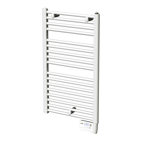
STUDIO 1 12volt LADDER TOWEL WARMER
The Advanced Art of Towel Warming
WARNING: This appliance is intended only for drying textiles washed in water.
WARNING: In order to avoid a hazard for very young children, this appliance should be installed so that the lowest
heated rail is at least 600 mm above the floor.
IMPORTANT: A means of disconnection in the fixed wiring must be used, which is in accordance with national wiring rules (ie
AS/NZS3000)
Operation
Your STUDIO 1 Towel Warmer uses only minimal electrical power - about the same as three LED lamps. It will take approximately
20-30 minutes to reach maximum operating temperature. STUDIO 1 Towel warmers are designed for continuous operation. NOTE:
The temperature of your towel warmer will vary with the ambient temperature of your room. A towel warmer is designed to warm and
assist the drying of towels and will normally operate at a temperature that is too hot for the warmer to be grasped for an extended
time.
Locating Instructions
Detailed installation instructions are provided on the reverse side. The STUDIO 1 Ladder Towel Warmer must be fixed through the
wall cladding directly to studs or other suitable anchor material. The towel warmer must be located in compliance with the AS/NZS
60335 Standard . STUDIO 1 LV towel warmers have an IP47 rating offering you the greatest flexibility to safely locate the towel
warmer in bathrooms or shower rooms in Zone 1-3. All other electrical fittings must also be compliant with the zone within which the
warmer is being installed.
Electrical Installation
This towel warmer must be installed by a registered electrician and ensure the electrical supply, transformer, plug & switch location,
and product location will comply with your local regulations. It must be installed with Heirloom transformer WTS12-100 The
transformer must be installed in an accessible location. If installed in a roof space, it must not be covered by insulation. The non-
connected side of the wiring must be protected from touching the stainless steel ladder. Do not connect both sides.
New Zealand electrical wiring requirements stipulate that this appliance must be wired by a registered electrician in accordance with
current electrical wiring regulations.
This product must be used in conjunction with a hard wired switch. For complete temperature control a wall mounted dimmer
switch (with “off” position) is recommended. Leading or trailing edge dimmers may be used.
Concealed Wiring Kit
A concealed wiring adapter kit is included with this product. If you have access to the wall cavity the kit allows you to conceal the
electrical flex for a more streamlined and visually appealing installation.
Care and Cleaning
The polished stainless steel finish of your Towel Warmer is hard wearing and easily maintained. Clean regularly with a soft cloth and
non-abrasive cleaning agent.
Warranty
This product is warranted against defects due to faulty workmanship or materials for 10 years from date of purchase. In the event of
a defect in the product, turn it off at the wall, and contact the retailer from which it was purchased and provide details from your
sales receipt and the products serial number from the label on the towel warmer. The retailer will contact Heirloom who will assess
the matter and if accepted as a valid warranty claim the product will be repaired or replaced at Heirloom’s option –free of charge.
Costs of disconnection, reconnection, and freight are the responsibility of the owner, as is any damage arising in transit to and from
servicing by Heirloom. This warranty does not cover:
a. Any damage to the product caused by misuse, neglect, accident, or in violation of the manufacturer’s instructions, or
b. Any damage, loss or injury arising as a consequence of the use of the product.
Australia: Our goods come with guarantees that cannot be excluded under the Australian Consumer Law. You are entitled to a
replacement or refund for a major failure and compensation for any other reasonably foreseeable loss or damage. You are also
entitled to have the goods repaired or replaced if the goods fail to be of acceptable quality and the failure does not amount to a
major failure.

STUDIO 1 12V v1 Jan 2020 Page 2of 3
INSTALLATION OF STUDIO 1 12 volt LADDER TOWEL WARMER
SPECIFICATIONS
Mounting Centre
(Approx Width)
Rating at 12 Volts AC
Voltage
IP Rating
WSLV825 (7 Rungs)
570mm
86 Watts
12v
IP47
WSLV825S (7 Rungs) Slimline
420mm
68 Watts
12v
IP47
WSLV510E (5 Rungs)
820mm
84 Watts
12v
IP47
WSLV510 (5 rungs)
570mm
61 Watts
12V
IP47
This Package Contains:
1 Ladder Towel Warmer
1 x Concealed adaptor fixing barrel 4 x Mounting Screws to fix Fixing Barrels to wall
2 x Top Mounting Legs with Fixing Barrel & Grub Screw & (Separate) Fixing bolt
1 x Bottom Mounting Leg (Non Flex Leg) with Fixing Barrel & Grub Screw
1 x Bottom Mounting Leg (Flex Leg) with Plastic grommet & Flat Fixing Bracket & M4 x10 Screw
1x PVC white flex (for exposed wire installations)
!x termination pack ( 2 x bootlace crimps and heat shrink)
CAUTION: Prior to installation please ensure the product is to your satisfaction. Once installed Heirloom cannot be responsible for defects in the
product finish. This product is not intended for use by young children or infirmed persons without supervision. Young children must be supervised
to ensure they do not play with the product. To minimize a hazard for young children, this appliance must be installed so that the bottom rail is
600mm above the floor. If the supply cord is damaged it must be replaced by the manufacturer, its service agent, or similarly qualified persons in
order to avoid a hazard.
Installation:
This towel warmer must be installed by a registered electrician and in accordance with local and national electrical codes. Use suitable size cable
for the installation We recommend that the towel warmer be installed vertically on a flat and uniform wall, and where possible into studs or other
suitable anchor material. If fixing to hollow cavity walls, Toggle Anchors (not those supplied) or similar devices must be used.
Position the towel warmer so that the towel warmer leads and flush box are easily accessible, with the cable entry to the towel warmer NEAREST
THE FLOOR. Avoid the supply cable coming into contact with the heated parts of the towel warmer.
DO NOT PLUG THE UNIT INTO THE POWER SUPPLY OR SWITCH THE TOWEL WARMER ON BEFORE INSTALLATION IS COMPLETE.
1 If the towel warmer is being installed with a concealed electric flex, read those instructions before returning to this point as preparatory
work is required before the wall cladding is installed on to the walls.
2 Identify the three different types of mounting legs per the above descriptions and attach the two top mounting legs to the towel warmer
with the fixing bolts (After removing the fixing barrels & making sure the grub screw will face the floor)
3 Decide which side the electric flex is to be connected and then connect the “Non Flex” Leg to the bottom of the towel warmer that will
not house the electric flex (After removing the fixing barrel & making sure the grub screw will face the floor). Also before attaching the
leg, shorten and insulate the wires on the side not being used.
4 Thread the “Flex Leg” on to the electric flex (ensuring that the leg is facing in the correct direction). Fix the leg to the towel warmer with
the two screws provided.
5 If the warmer is being installed without using the concealed adaptor (i.e. the electric flex is to be visible) proceed to the next step. Use
the white tube, cut to length to cover the leads. If the towel warmer is being installed with a concealed wiring fixing adaptor, proceed to
that section.
6 Hold the towel warmer in position and mark around one of the top legs. Remove the towel warmer and fix the fixing barrel to the wall.
7 Ensuring that mounting points are level (horizontal), mark the second point. . Fix the mounting barrel to the wall. Should the towel
warmer not be sitting square, do not proceed further with installation without rectifying problem.
8 Place the towel warmer onto the two fixing barrels and mark the location of the two bottom legs.
9 Remove the towel warmer and fix the remaining fixing barrel and fixing bracket to the wall. Ensure that the metal fixing bracket is used
for the foot that contains the electric flex. (The other three feet will use the same style of fixing bracket)
10 A length of PVC flex is supplied for exposed flex installations. Use bootlace crimps and heat shrink to joint towel warmer leads to this
flex. Ensure the flex exits the leg through the slot with the plastic edge.
11 Place the towel warmer in position and secure it to the fixing barrels using the grub screws.
12 Connect the towel warmer leads to the supply from the transformer.

STUDIO 1 12V v1 Jan 2020 Page 3of 3
Concealed Wiring Option Instructions:
.
1. Ensure that the flush box that the towel warmer will be wired to can be reached by the flex from the mounting position of the towel
warmer. Allow for loss of flex length due to connections.
2. Drill a 12.5mm hole into the face of the stud where the towel warmer foot with the flex is to be positioned. Drill the hole approximately
25mm deep. (On masonry walls drill a 14mm hole.)
3. Identify the side of the stud facing the flush box that the towel warmer will be wired to. On that side of the stud, drill a 25mm deep hole
at right angles to this first hole so that the hole will break into the base of the first hole. Refer to Fig1.
4. Place a pull through line from the flush box and out the 12.5mm hole so that the line can be picked up later once the wall cladding is in
place
5. When the wall cladding is installed a hole will be required to provide access to the above 12.5 mm hole in the stud. Locate the pull
through and leave hanging out of the hole that has been created in the wall cladding. (NOTE: care must be taken to ensure that the
hole created in the wall cladding is a lesser diameter than that of the towel warmer leg to ensure that the hole in the cladding will be
concealed by the towel warmer leg when it is fixed into position)
6. When installing the towel warmer, thread the pull through line, through the concealed mounting adaptor and screw the mounting
adaptor into position. The pull through line must now exit through the concealed wiring adaptor. (On masonry walls epoxy resin the
adaptor into position). (refer Fig 2)
7. For the second bottom leg of the towel warmer mark a point horizontally from the centre of the adaptor at the measurement for your
model (but check the actual measurements to your warmer as manufacturing tolerances apply) for the other bottom fixing barrel. It is
important that the line between these two points is level.
8. Screw the other bottom mounting bracket into place with the screws provided.
9. If applicable, fit the trim to the Concealed mounting adaptor, attach the pull through to the flex and pull the flex through the stud holes to
the flush box.
10. Position the towel warmer on the bottom two mounting brackets / barrels and mark the position of the two top feet. (Use easy to remove
pencil)
11. Mark the centre distance for the top mounting brackets / barrels (per above) & screw the mounting brackets / barrel to the wall.
12. If applicable, fit the trims on the 3 remaining mounting brackets.
13. Remount the towel warmer on the four mounting brackets / barrels. Secure the foot containing the flex with the screws provided, then
secure the three remaining feet with the screws provided.
Heirloom International Limited, P O Box 204 235, Auckland 2161, New Zealand.
Contact Us
We welcome your feedback on our products. You can view our full range of towel warmers on our website and send us your
comments about this product using the Contact Us page on our website www.heirloom.co.nz
At centre measurement for your model
This manual suits for next models
4
Table of contents
Popular Heater manuals by other brands
LVI
LVI JARL Instructions for fitting and use

Olimpia splendid
Olimpia splendid CALDODESIGN Instructions for use and maintenance
Fagor
Fagor TRV-220 Instructions for use

NARVI
NARVI Steam Master installation, user and maintenance instructions

Proheat
Proheat Teleflex X45 Installation and service
Perel
Perel TC78049N user manual
