Proheat Teleflex X45 Manual

INSTALLATION
AND SERVICE
MODEL X45


CONTENTS
INTRODUCTION...........................................................................i
1. OPERATING YOUR PROHEAT HEATER ..................................1-1
2. TECHNICAL SPECIFICATIONS
ENCLOSURE DIMENSIONS ..........................................................2-1
HEATER DIMENSIONS .................................................................2-2
3. INSTALLATION
LOCATING THE HEATER...............................................................3-2
MOUNTING THE HEATER .............................................................3-4
EXHAUST PIPE CONNECTION .......................................................3-6
PLUMBING THE SYSTEM .............................................................3-7
General Considerations.........................................................3-7
Option A – Engine Heat or Supplemental Heat ........................3-8
Option B – Engine & Sleeper Heat..........................................3-9
Engine Connection Details...................................................3-11
WIRING & ELECTRICAL CONNECTIONS .......................................3-13
General Considerations.......................................................3-13
Power Connection to Batteries.............................................3-14
Timer Connections..............................................................3-15
On/Off Switch ....................................................................3-16
Sleeper Heater Wiring Details..............................................3-17
Option A – OEM Heater & PROHEAT Thermostat....................3-17
Option B – OEM Heater & Thermostat ..................................3-18
Option C – Auxiliary Sleeper Heater ......................................3-19
Option D – Relay Sleeper Heater..........................................3-20
FUEL SYSTEM ..........................................................................3-21
General Considerations.......................................................3-21
Option A – 1⁄4" OR 1⁄2" NPT Port...........................................3-22
Option B – Existing Blank Fuel Sender Cover Plate ................3-23
Option C – Hole Drilled into Fuel Tank ..................................3-23
Installation.........................................................................3-24
FIRST TIME STARTUP ................................................................3-25
4. PRINCIPLES OF OPERATION
GENERAL DESCRIPTION ..............................................................4-1
NORMAL OPERATING SEQUENCE .................................................4-5
5. TROUBLESHOOTING & REPAIR
“ON” Indicator Light..............................................................5-1
FUNCTION DIAGNOSTICS.............................................................5-2
Start....................................................................................5-2
Flame Out ............................................................................5-3
Coolant Flow ........................................................................5-4
Overheat..............................................................................5-5
Voltage ................................................................................5-6

COMPONENT DIAGNOSTICS.........................................................5-8
Flame Sensor.......................................................................5-8
Temperature Sensor ...........................................................5-10
Fuel Pump..........................................................................5-12
Compressor .......................................................................5-13
Ignition Coil........................................................................5-15
Coolant Pump ....................................................................5-17
Blower ...............................................................................5-19
Sleeper Fan .......................................................................5-21
COMPONENTS..........................................................................5-22
Electrode Gap ....................................................................5-22
Fuse ..................................................................................5-23
Nozzle ...............................................................................5-25
Fuel Regulator ....................................................................5-26
FUEL SYSTEM ..........................................................................5-27
General..............................................................................5-27
OPERATIONAL PROBLEMS .........................................................5-29
Smoking Exhaust................................................................5-29
Low Heat Output.................................................................5-29
Engine Temperature Gauge .................................................5-29
Backfiring...........................................................................5-29
6. MAINTENANCE
Weekly Maintenance.............................................................6-1
Annual Maintenance .............................................................6-1
Clean Heater Enclosure.........................................................6-1
Heat Exchanger ....................................................................6-2
Exhaust System ...................................................................6-2
Electrical System..................................................................6-3
Clean Air intake ....................................................................6-3
Fuel System .........................................................................6-4
Vehicle Batteries ..................................................................6-4
Operation Test .....................................................................6-5
PCM: Pin-out Details .............................................................6-5
Proheat Wiring Diagram.........................................................6-6
7. WARRANTY .............................................................................7-1
8. APPENDICES
Service Bulletin #951528.........................................8-3
#967329.........................................8-5
SB0003...........................................8-7

i
INTRODUCTION
This manual is provided to assist an authorized
PROHEAT dealer to install and service a PROHEAT
heater. Although trucks have been used in the
examples, applications for PROHEAT are by no means
limited to trucks. PROHEAT heaters are designed to be
used on any diesel equipped vehicle including: trucks,
buses (school, transit and coach), construction
equipment, off road equipment, military equipment
and cargo.
PROHEAT heaters are used in the following applications:
(1) Engine Block Heat – PROHEAT will preheat an
engine block to ensure reliable starting in cold
weather. At the same time it may be used
throughout the year to reduce the wear associated
with cold starts.
(2) Cab or Sleeper Heat (engine off) – PROHEAT will
supply heat to the cab or sleeper. Drivers can
sleep in comfort not only in the cold of winter
but also in the spring and fall when the weather
is miserable. Substantial savings through reduced
fuel consumption and engine wear can be
obtained by not idling the engine.
PROHEAT Model X45
(3) Supplemental Heat (engine running) – as the
efficiency of modern diesel engines are improved
there is no longer adequate reject heat available
to heat the vehicle’s interior. This is particularly
true for buses. PROHEAT can be used while
the vehicle is operating to provide supplemental
heat for the interior.
(4) Cargo Heat – PROHEAT can be used to provide
heat to protect valuable cargo such as produce
or beverages from damage due to freezing.
(5) Marine – Marine applications typically involve
the engineering and installation of a complete
hot-water heating system of which PROHEAT
is only one component. Teleflex recommends
that only an expert in marine hot-water heating
systems install a PROHEAT on a boat.
It is the installer’s responsibility to ensure
that the installation complies with all applicable
Coast Guard regulations.


OPERATING YOUR PROHEAT HEATER 1-1
OPERATING YOUR
PROHEAT HEATER
Engine Heat Only
1. Switch the ON/OFF switch located in the vehicle dash to “ON.”
The switch will light and the heater will fire. It will continue to fire
until the coolant reaches 185˚F (85˚C) at the heater outlet and then
cycle “OFF.”
When the coolant temperature falls below 150˚F (65˚C) at the heater
outlet, it will refire and repeat the cycle.
It will continue to cycle until:
a) the heater is switched “OFF,”
b) the heater runs out of fuel,
c) the vehicle battery voltage drops below 10.0 Volts, or
d) an error occurs and the switch light flashes
(See Troubleshooting & Repair, Section 5)
NOTE: The PROHEAT may be operated if the engine is running
or not running.
2. When engine preheat is no longer required,
switch the PROHEAT heater “OFF.”
Engine and Sleeper Heat
1. Switch the ON/OFF switch located in the vehicle dash to “ON.”
The switch will light and the heater will fire. It will continue to fire
until the coolant reaches 185˚F (85˚C) at the heater outlet and then
cycle “OFF.”
When the coolant temperature falls below 150˚F (65˚C) at the
heater outlet, it will refire and repeat the cycle.
It will continue to cycle until:
a) the heater is switched “OFF,”
b) the heater runs out of fuel,
c) the vehicle battery voltage drops below 10.0 Volts, or
d) an error occurs and the switch light flashes
(See Troubleshooting & Repair, Section 5)
NOTE: The PROHEAT may be operated if the engine is running
or not running.
2. For sleeper heat – set the thermostat in the sleeper to the desired
temperature. If the set temperature is higher than the temperature
in the sleeper the fan will cycle “ON.” When the air reaches the set
temperature the fan will cycle “OFF.” The fan will cycle “ON” and “OFF”
to maintain the set temperature.
3. When engine and/or sleeper preheat is no longer required,
switch the PROHEAT heater “OFF.”
1.0
NOTE:
Regular use of your PROHEAT
throughout the year will improve
its reliability. Weekly operation is
recommended.
NOTE:
The PROHEAT heater can be
operated by either using a toggle
switch or a 7 day timer.
Refer to Page 3-13 for WIRING &
ELECTRICAL CONNECTIONS.

TECHNICAL SPECIFICATIONS
Model Heat Rating Volts Current Fuel Rate Coolant Flow
BTU/hr. (kw) Nominal Amps Gal/hr (l/hr) Gal/min (l/min.)
(range)
X45-12 45,000 12 7.5 .32 (1.2) 8.0 (30)
(13.0) (10.0 – 15)
X45-24 45,000 24 3.75 .32 (1.2) 8.0 (30)
(13.0) (20 – 30)
2-1
TECHNICAL
SPECIFICATIONS
Ignition Type: .................................Electronic spark ignition
Fuel Types:.....................................Diesel #1, #2, Kerosene
Coolant Temperature: .....................150˚ to 185˚F (65˚ to 85˚C) @ heater
Enclosure Dimensions: X45...........12 1⁄2 W x 11 H x 20 1⁄2 L inches
(318 x 280 x 521 mm)
Weight, Heater only: X45...........40 lbs. (18 kg)
Weight, with Enclosure: X45...........55 lbs. (25 kg)
Operating Temperature Range:........-40˚ to 122˚F (-40˚ to 50˚C)
Heat Exchanger Capacity:...............1 quart U.S. (0.97 litre)
WARNING
DO NOT use gasoline
2.0
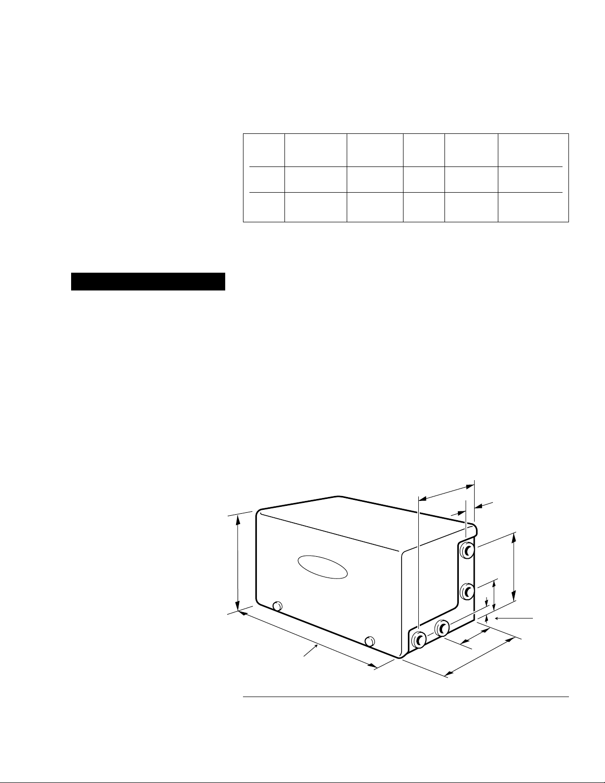
Figure 2-1 Enclosure Dimensions
10 1/8"
(241 mm)
1 1/4"
(31 mm)
8 1/2"
(216 mm)
3 7/8"
(92 mm)
1 7/16"
(36 mm)
7 5/16"
(186 mm) 12 1/2" (318 mm)
20 1/2" (521 mm)
11"
(280 mm)
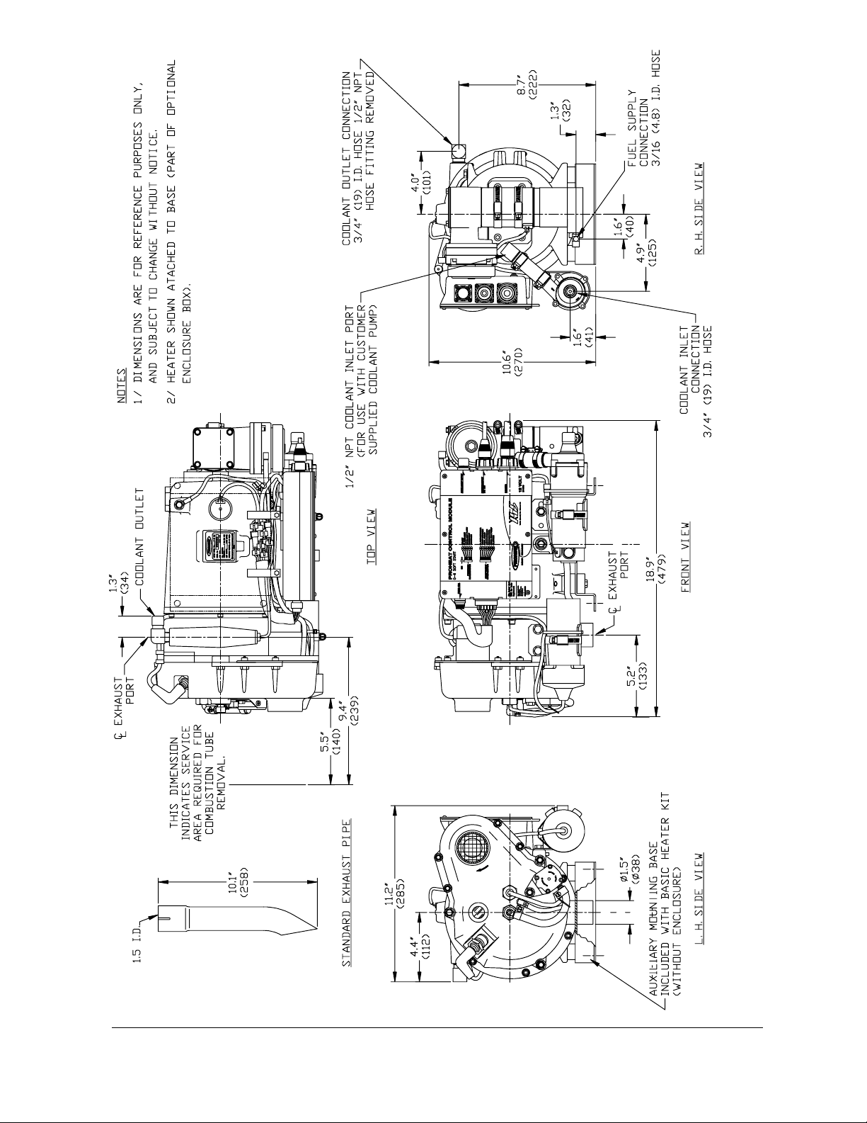
Figure 2-2 Heater Dimensions X45
PROHEAT INSTALLATION & SERVICE
2-2

INSTALLATION 3-1
INSTALLATION
There are seven major steps that must be completed to successfully
install the PROHEAT heater.
1. LOCATING THE HEATER ......................................................3-2 to 3-3
2. MOUNTING THE HEATER.....................................................3-4 to 3-5
3. EXHAUST PIPE CONNECTION ........................................................3-6
4. PLUMBING THE SYSTEM.....................................................3-7 to 3-9
5. WIRING & ELECTRICAL CONNECTIONS.............................3-13 to 3-20
6. FUEL SYSTEM................................................................3-21 to 3-24
7. FIRST TIME STARTUP......................................................3-25 to 3-26
NOTE: The installation details described in this manual may not cover
all of the application possibilities. In these cases this manual
should be used as a guideline only. If additional installation
information is required please contact your PROHEAT Dealer
regarding your specific application.
Prior to the installation of your PROHEAT, consult your engine owner’s
manual or engine manufacturer for any restrictions or changes that may
apply to plumbing into the engine coolant system.
3.0
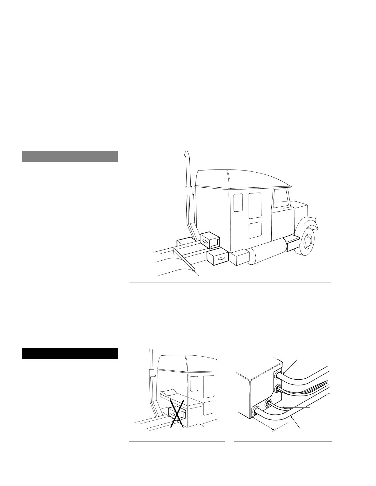
Figure 3-3 Allow minimum 6" clearance
for hose connections.
PROHEAT INSTALLATION & SERVICE
3-2
Select Your Location
The most suitable location for mounting the heater will vary depending
on the type of vehicle. Recommended mounting locations are:
• Behind the cab across the frame rails (1).
• On either side of the frame rails (2).
• In an existing enclosure on the vehicle (step or toolbox) (3).
Locating the Heater
GENERAL CONSIDERATIONS
• Never mount the heater to two separate parts of the vehicle.
• Avoid mounting the heater to fenders or areas of excessive vibration.
• Do not mount the heater directly to the engine.
Figure 3-1 Recommended Mounting Positions
Caution
Do not weld PROHEAT heater
mounting brackets to the
vehicle frame.
If repairs to the vehicle require
welding, disconnect the PROHEAT
power cable at the PCM. This will
prevent damage to the PROHEAT
electronics.
You Choose ☞
Figure 3-2
WARNING
Never locate the heater inside
the vehicle cab. (See Figure 3-2)
1
2
2
3
COOLANT OUT
COOLANT IN
MINIMUM
CLEARANCE 6"
FUEL IN

Figure 3-5 Adequate Air Flow
Figure 3-4 Height Requirement
INSTALLATION 3-3
Heater must be mounted below the highest point in the cooling system.
Mounting the PROHEAT heater in an enclosure
Do not locate the heater in an
airtight enclosure. If the heater
is to be mounted in an enclosure
other than the PROHEAT enclosure,
adequate air flow must be provided
to ensure proper combustion.
Figure 3-6 Mounting Angle
Heater must be mounted within 5˚ of horizontal, as shown.
HIGHEST POINT IN
COOLING SYSTEM
HEATER MUST
BE MOUNTED
BELOW
HIGHEST POINT
PROHEAT ENGINE OR RADIATOR
5˚
5˚
5˚
5˚
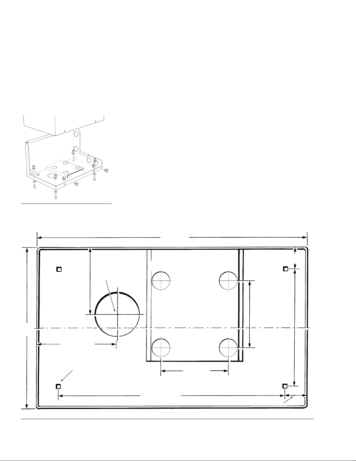
Figure 3-8 X45 Enclosure Base Dimensions
PROHEAT INSTALLATION & SERVICE
3-4
Mounting the Heater
Select Your Mounting Option
Heater supplied with an enclosure.
1. Remove the enclosure cover.
2. Drill the (4) mounting holes and exhaust pipe clearance hole.
3. Using the bolts supplied, fasten the enclosure to the mounting
tray or brackets.
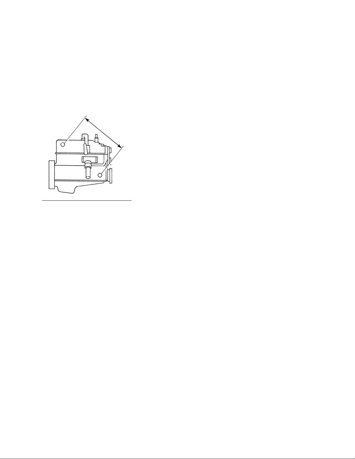
4. Ensure that the combustion tube can be removed for service.
Minimum of 5 1⁄2" from fan end casting face is required.
NOTE: Use anti-seize compound on fasteners to prevent galling
and corrosion.
OPTION A:
Figure 3-7 Mounting Tray
8 13/16"
(223 mm)
5 3/4" (146 mm)
3/4" (20 mm) MOUNTING HOLES
(4 REQUIRED)
16 11/16" (427 mm)
12"
(306 mm)
20" (508 mm)
5" (127 mm)
3" (76 mm) Dia.
5" (127 mm)
CENTERLINE OF ENCLOSURE
5" (127 mm)
1 5/8"
(45 mm)
1 5/8" (45 mm)
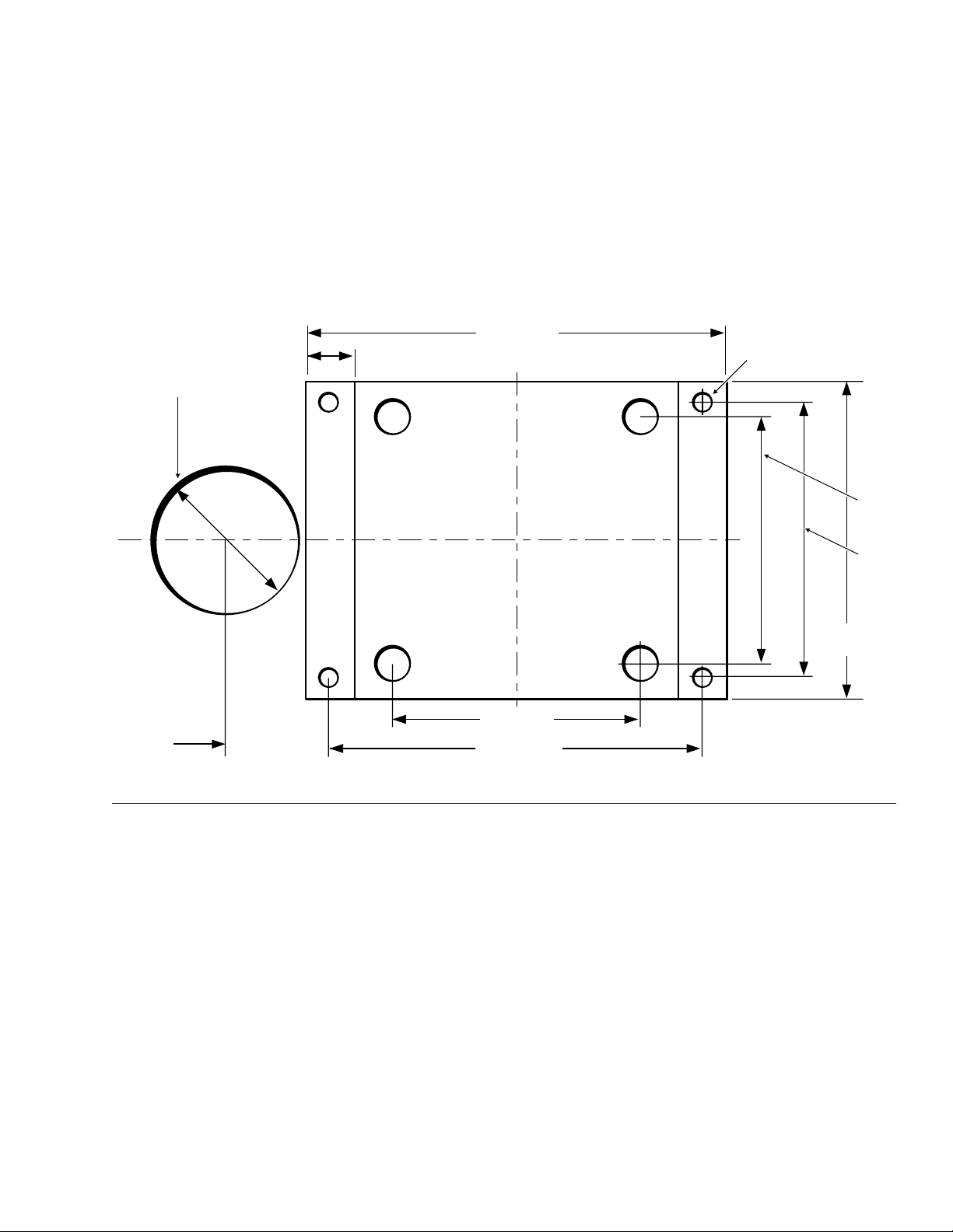
Figure 3-9 X45 Mounting Plate Dimensions & Exhaust Hole
INSTALLATION 3-5
Heater supplied without an enclosure (mount in an existing enclosure on
the vehicle ie. tool box). Heater supplied with an auxiliary mounting plate.
1. Ensure that the proposed enclosure is big enough for the heater.
12 1⁄2W x 11H x 20 1⁄2L inches (318 x 280 x 521 mm)
2. Using the indicated dimensions, drill the (4) mounting holes
and exhaust pipe clearance hole.
3. Ensure that the combustion tube can be removed for service.
Minimum of 5 1⁄2" from fan end casting face is required.
OPTION B:
2.02"
(51 mm)
3" (76 mm) Dia.
5.5"
(140 mm)
1.0" (25 mm)
8.5" (216 mm)
5"
(127 mm)
5" (127 mm)
7.5" (191 mm)
4 X .38" (10MM)
MOUNTING HOLES
6.4"
(163mm)
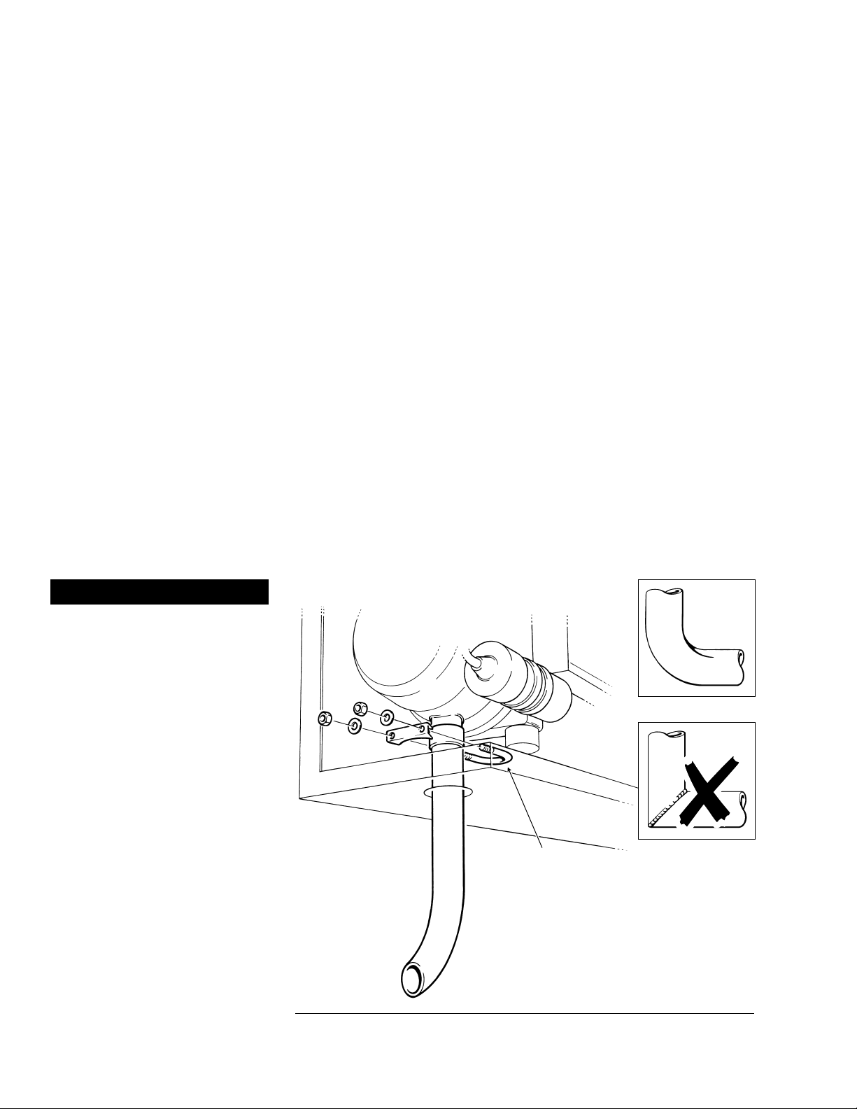
Figure 3-10 Exhaust Pipe
PROHEAT INSTALLATION & SERVICE
3-6
Exhaust Pipe
Connection
1. Push the exhaust pipe through the hole in the enclosure and onto
the exhaust outlet port of the heater. Ensure that the pipe is pushed
onto the spigot at least 11⁄2" (38 mm).
2. Route the exhaust pipe such that:
a) It does not rest against or be directed toward any parts.
of the vehicle that may be damaged by heat (i.e. brake lines,
seals, wires, rubber hoses).
b) Debris and snow will not plug the outlet.
c) Moisture from combustion will drain out of the pipe.
d) It does not face forward.
3. Disassemble the exhaust pipe clamp and apply anti-seize compound
to the threads.
4. Assemble the exhaust clamp over the exhaust pipe (clamp goes
inside the enclosure) and tighten the nuts.
NOTE: 11⁄2" exhaust pipe should not exceed 5 ft and have no more than
180 degrees of bends. The bends must be formed for best results.
Do not use 90 degree welded pipe to turn corners.
NOTE: For installations requiring special exhaust systems, consult your
PROHEAT Dealer.
WARNING
Exhaust gases must not enter
the vehicle interior. Direct
exhaust pipe away from
vehicle.
EXHAUST CLAMP
U BOLT
(APPLY ANTI-SEIZE
COMPOUND TO
THREADS)
Use formed elbows.
Do not use welded
90˚ elbows.
INSTALLATION 3-7
GENERAL CONSIDERATIONS
Coolant flow must be maintained throughout the coolant system
under all conditions.
• Keep the engine inlet and outlet ports as far apart as possible
to maximize cross-flow through engine.
• Ensure that no sharp kinks or bends exist in the hoses
which may restrict coolant flow.
• Avoid high points in the hose routing to prevent air traps.
• For systems requiring more than 50 feet of coolant line,
consult factory for coolant pump recommendations.
For plumbing the system use:
1⁄2" NPT pipe fittings or bigger.
3⁄4" ID heater hose.
NOTE: Use of silicone hose requires special hose clamps.
Shut-off valves are not required at the engine inlet and outlet connections
but may be used if desired. They should be left open at all times so that
the heater can be operated throughout the year.
Select Your Plumbing Option
OPTION A: Engine heat or supplemental heat.
The PROHEAT heats the engine block only.
NOTE: When the engine block is preheated you will have
nearly instant heat from the dash heat exchanger.
OPTION B: Engine and sleeper heat.
The PROHEAT heats the engine block and the sleeper.
NOTE: Plumbing the PROHEAT through the dash fan
is not recommended.
Plumbing the System
You Choose ☞
Figure 3-11 Maximize cross-flow
MAXIMUM CROSS-FLOW
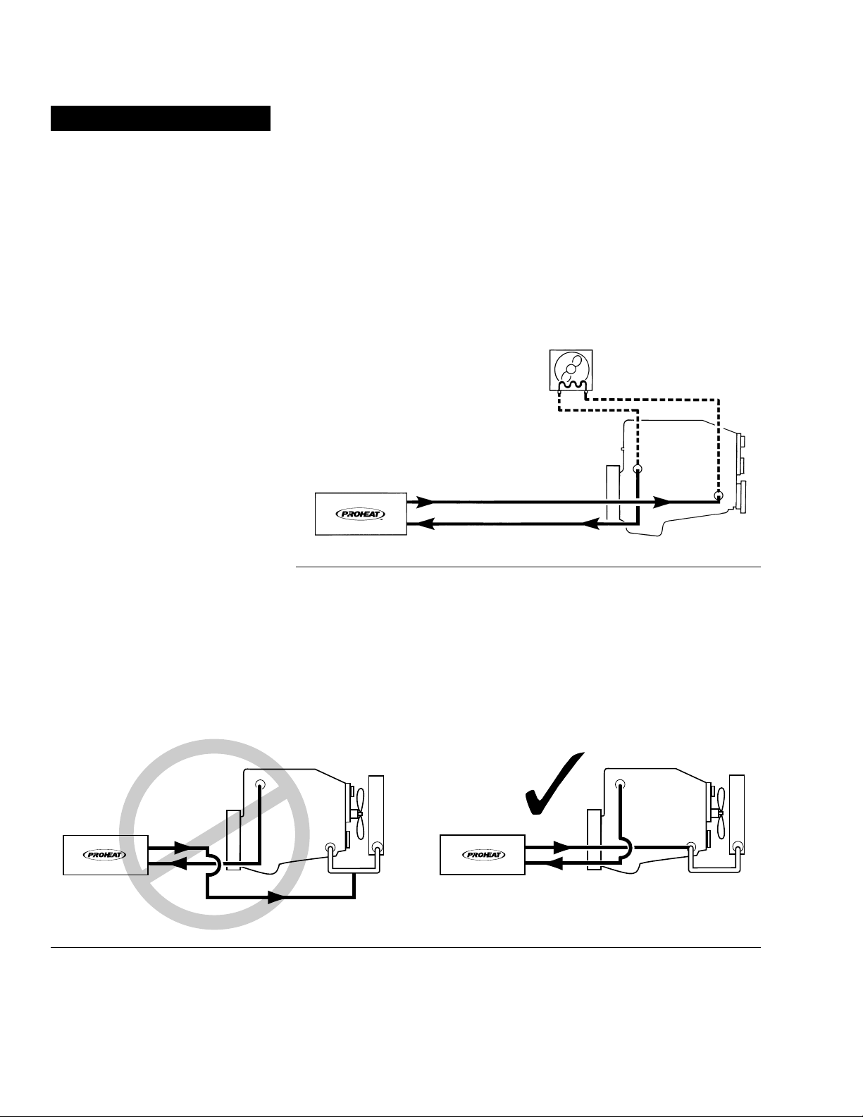
Figure 3-12 Engine Heat or Supplemental Heat
PROHEAT INSTALLATION & SERVICE
3-8
Engine Heat or Supplemental HeatOPTION A:
WARNING
Opening the radiator cap when
the engine is hot may cause
serious injury.
Instructions for Options A and B
1. Remove the radiator cap to release the system pressure.
2. Drain the coolant system.
3. Plumb the system as per Figure 3-12 or Figure 3-14
4. Add engine coolant to the system as per the specific engine
manufacturer’s recommendations and re-install the radiator cap.
NOTE: Plumbing the PROHEAT through the dash fan is not recommended.
NOTE: On coolant systems where the return from the PROHEAT is plumbed
to the bottom of the main coolant supply line from the radiator to
engine pump, the return line must be moved to avoid loss of heat
through the radiator.
DASH HEATER
ENGINE
RETURN TO ENGINE
SUPPLY TO PROHEAT
NOTE: Specific engine
connection details by
manufacturer and model
can be found at the end of
this section.
Figure 3-13 Correct Return Line Plumbing
®®
ENGINE
ENGINE
SUPPLY TO PROHEAT
RETURN TO ENGINE
SUPPLY TO PROHEAT
RETURN TO ENGINE

Figure 3-15 Engine and Sleeper Heat
Figure 3-14 Engine and Sleeper Heat
INSTALLATION 3-9
OPTION B: Engine and Sleeper
For vehicles with solenoid
valves in the normally closed
position.
Western Star
For best results these vehicles
should use an auxiliary heater.
International with single heater
NOTE: Vehicles equipped with a combination heater/air-conditioner will
have a solenoid operated shut-off valve in the heater unit. Typically
this valve is normally open with the truck engine turned off and the
key removed. (See Figure 3-15 for plumbing)
Due to the many options available in vehicle heating and air conditioning
systems, the installer should be looking for any restrictions that may affect
coolant flow, with vehicle ignition in the “OFF” position.
DASH HEATER
ENGINE
SUPPLY TO PROHEAT
RETURN TO ENGINE
OEM OR AUXILIARY
SLEEPER HEATER
SOLENOID VALVE
OEM COMBO HEATERS
ONLY (NORMALLY OPEN)
NOTE: Specific engine connection details by
manufacturer and model can be found
at the end of this section.
DASH HEATER
SUPPLY TO PROHEAT
RETURN TO ENGINE
SLEEPER HEATER
SOLENOID VALVE
(NORMALLY CLOSED)
ENGINE
NOTE:
The PROHEAT PCM sleeper fan
circuit has a one minute delay
during ignition. Power to open a
sleeper fan coolant valve must be
taken from another source such
as the wire for the hour meter.
(See PROHEAT Wiring Diagram
page 6-6)

Other manuals for Teleflex X45
2
Table of contents
Other Proheat Heater manuals


Popular Heater manuals by other brands

Vornado
Vornado Vortex Heater VH2 user guide

EUROM
EUROM GOLDEN 2000 AMBER SMART instruction manual

Stelpro
Stelpro SDHR Series Installation and user guide

Clarke
Clarke 6933980 Operation & maintenance instructions

VOLTOMAT HEATING
VOLTOMAT HEATING FH-110692.1 instruction manual

Dimplex
Dimplex R23DH Series quick start guide


