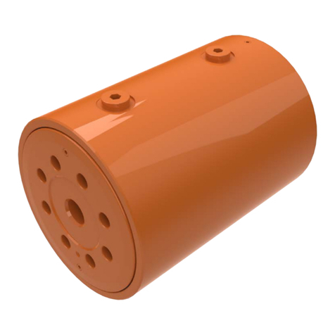
Helac L20 Series Installation and operating manual

Helical Hydraulic
Rotary Actuators
L20 Series Service & Repair Manual

2Parker Hannifin Corporation
Helac/Cylinder Division
Enumclaw, Washington USA
www.helac.com
Helical, Hydraulic Rotary Actuators
L20 Series Service & Repair Manual
Catalog HY34-1120
Table of Contents
Table of Contents
Introduction
Table of Contents..................................................................................................................................................... 2
Product Introduction................................................................................................................................................. 3
General Safety Guidelines....................................................................................................................................... 3
Product Identication ............................................................................................................................................... 4
Operation Technology.............................................................................................................................................. 5
Tools
Tools Required......................................................................................................................................................... 6
Drawings
Spare Parts.............................................................................................................................................................. 7
Assembly Drawing................................................................................................................................................... 8
Exploded View......................................................................................................................................................... 9
Parts List..................................................................................................................................................................10
Disassembly
Before Disassembly................................................................................................................................................. 11
Disassembly ............................................................................................................................................................ 11
Inspection ................................................................................................................................................................16
Assembly
Assembly ................................................................................................................................................................17
Post Assembly
Grease Thrust Washers...........................................................................................................................................22
Testing the Actuator.................................................................................................................................................23
Installation and Bleeding..........................................................................................................................................24
Troubleshooting Guide ........................................................................................................................................... 25
Warranty Information ............................................................................................................................................... 26

3Parker Hannifin Corporation
Helac/Cylinder Division
Enumclaw, Washington USA
www.helac.com
Helical, Hydraulic Rotary Actuators
L20 Series Service & Repair Manual
Catalog HY34-1120
Product Introduction & Safety Guidelines
General Safety Guidelines
Product Introduction
Many L20 actuator applications have several pinch
points with the potential for severe injuries. Use
extreme caution and remain clear of all rotating
components when bleeding the hydraulic system
and whenever the machine is in operation.
After rebuilding or repairing an actuator, it is
necessary to bleed all air from the actuator as well
as the hydraulic system of the machine. See page
25 for bleeding instructions.
Exercise extreme caution while bleeding the
actuator -- keep hands, ngers, and other limbs a
safe distance from all rotating components.
For over 45 years, Helac Corporation has
been recognized for innovation in design of
hydraulic rotary actuators and construction
equipment attachments. Helac products
are renowned for their tremendous torque
output, compact congurations, exceptional
load bearing capabilities, and rugged,
reliable performance. Over 1,000 mobile,
industrial, construction and mining machinery
manufacturers around the world depend on
Helac actuators to perform such functions as
rotation, positioning, manipulation, vehicle
steering and indexing. Helac's L20 Series
rotary actuators are used widely to rotate work
platforms on self-propelled aerial lifts where
they have become the industry standard.
The L20 Series is available in dierent sizes
and various mounting congurations (for more
details see page 4).
Avoid personal injury and
machinery damage:
Read the Service and Repair Manual
for proper installation, maintenance
and repair procedures.
Spraying fluids.
Contents under pressure.
Wear approved eye protection.
Use caution when removing
port plugs and fittings.
To avoid contamination
to machined parts:
Make sure work area is clean.
To avoid injury or damage
to product:
Secure product to slotted table or vise.

4Parker Hannifin Corporation
Helac/Cylinder Division
Enumclaw, Washington USA
www.helac.com
Helical, Hydraulic Rotary Actuators
L20 Series Service & Repair Manual
Catalog HY34-1120
Product Indentification
Product Identification
Each Helac actuator is individually serial
numbered. The serial number is a ve or six digit
number and must be provided before parts and/
or service issues can be addressed.
The serial number can be found on the
Identication (ID) Tag that is axed to all
actuators.Thetagisathin,silvercolored,plastic
materialwithaself-adhesivebacking.Information
is imprinted in black. The tag is located either
on the side plate or on the housing tube of the
actuator. In some cases, the ID tag may be
painted over by the OEM (Original Equipment
Manufacturer). Typical sample tag locations are
seen below. Note that the model number may
begin with either "HP" or "L20".
Additionally, the serial number of the actuator is
stampedontothesideplateorthehousingtube.
It may be necessary to remove paint to expose
the serial number.
IftheIDtagisnotattachedtotheactuatorand/or
the stamped serial number cannot be located,
the basic actuator model can be identied by
measuring the outer diameter of the drilled and
tapped shaft ange.
Model Flange Diameter
L20-4.5 4.10” (104.14 mm)
L20-8.2 4.60” (116.84 mm)
L20-15 5.60” (142.24 mm)
L20-25 6.70” (170.18 mm)
L20-30 7.20” (182.88 mm)
L20-39 7.70” (195.58 mm)

5Parker Hannifin Corporation
Helac/Cylinder Division
Enumclaw, Washington USA
www.helac.com
Helical, Hydraulic Rotary Actuators
L20 Series Service & Repair Manual
Catalog HY34-1120
Operation Technology
OperationTechnology
The L20 Series rotary actuator is a simple
mechanism that uses Helac's sliding spline
technology which converts axial piston motion
into powerful shaft rotation. As seen in the
illustrationbelow left,eachactuatoriscomposed
of a housing with an integral ring gear (1) and
only two moving parts: the central shaft (2),
and the annular piston sleeve (3). Note the L20
actuator shaft features an integral mounting
ange and bearing which are not shown in the
illustration.
Helical spline teeth machined on the shaft
engage matching splines on the inside diam-
eter of the piston. The outside diameter of the
pistoncarriesasecondsetofsplines,of opposite
hand, which engage the matching splines of the
housing's ring gear.
As hydraulic pressure is applied, the piston is
displaced axially within the housing - similar
to the operation of a hydraulic cylinder - while,
simultaneously, the splines cause the shaft to
rotate. When the control valve is closed, oil is
trapped inside the housing, preventing piston
movement and locking the shaft rmly in position.
Theshaft issupported radiallybythelargeupper
radial bearing and the lower radial bearing (see
drawings on pages 8 and 9). Axially, the shaft
is separated from the housing by the upper and
lower thrust washers. The end cap is adjusted
for axial clearance and locked in position by set
screws or pins.
The L20 Series is available in several dierent
sizes. All L20 Series actuators have the same
internal design and basic components, though
congurations of parts may be slightly dierent
depending on model.
Many L20 actuators are equipped with factory
installed counterbalance valves, which perform
four major functions.
• Protectstheactuatorintheeventofoverload
• Enables the actuator to hold position without
drifting when external loads are applied
• Reduces hydraulic backlash by pressuring
the hydraulic uid
• Providesaconstantcontrolledrateofrotation
in over-center load conditions
Bars indicate starting positions of piston
and shaft. Arrows indicate direction they
will rotate. The housing with integral ring
gear remains stationary. For clarity, the
shaft ange, bearings, and end cap are not
shown.
Applying uid pressure will displace the
piston axially while the helical gearing causes
the piston and shaft to rotate simultaneously.
The double helix design compounds rotation:
shaft rotation is about twice that of the piston.
Applying pressure to the opposite port will
return the piston and shaft to their original
starting positions.
3
2
1

6Parker Hannifin Corporation
Helac/Cylinder Division
Enumclaw, Washington USA
www.helac.com
Helical, Hydraulic Rotary Actuators
L20 Series Service & Repair Manual
Catalog HY34-1120
Tools Required
Tools Required
MAKING A SEAL TOOL
The seal tool is merely a customized stan-
dard at head screwdriver.
1. Heat the at end with a torch until it
glows.
2. Secure the heated end of the screw-
driver in a vise and bend the heated end
to a slight radius.
3. Round o all sharp edges of the heated
end to a polished nish. The tool may be
modied slightly to your own personal
preference.
Several basic tools are required for the
disassembly and reassembly of the actuator. The
tools and their intended functions are outlined
below:
1. PIPEVISE
2. TORQUEWRENCH
Removal and replacement of port plugs and
set screws.
3. ASSORTED SCREWS
4. SAFETY GLASSES
5. END CAP REMOVALTOOLS (provided with
Helac seal kit).
6. DRILL
7. FLASHLIGHT
Helps in locating and examining timing marks,
component failure and overall condition.
8. RUBBER MALLET
Removal and installation of shaft and piston
sleeve assembly.
9. PLASTIC MANDREL
10. PRY BAR
Removal of end cap and manual rotation
of shaft.
11. FELT MARKER
Highlights timing marks and outlines troubled
areas. Permanent ink is recommended.
12. T-HANDLE SCREW EXTRACTOR
13. HEXWRENCH SET
Removal and replacement of port plugs and
set screws (106,113).
14. SEALTOOLS
Removal and installation of seals and wear
guides. Directions on making a seal tool are
provided at bottom.
15. PUNCH
16. DOWEL PINS
Removal and installation of end cap.
6.
1.
2. 3. 4.
8.
7.
9. 10.
5.
11. 12. 13.
14. 15. 16.

7Parker Hannifin Corporation
Helac/Cylinder Division
Enumclaw, Washington USA
www.helac.com
Helical, Hydraulic Rotary Actuators
L20 Series Service & Repair Manual
Catalog HY34-1120
Spare Parts & Technical Support
Technical Support
Spare Parts
Sparepartsmustbeorderedthroughthevehicle/
machineOEM.Sealsandbearingsareavailable
as complete kits only. In order to obtain the
correct parts, it is essential to provide the serial
numberoftheactuatortoberepaired,seeProduct
Identication section on page 4. To identify spare
partsrequired,refertotheAssemblyDrawingon
page 8 and Parts List on page 10.
Technical support is available from Helac Corporation, Monday through Friday 7 am to 4 pm
Pacic Standard Time by calling 800-327-2589. If possible, please have the serial number of the
actuator available. (The serial number is stamped into the housing of the actuator-see page 4).
Spare Parts

8Parker Hannifin Corporation
Helac/Cylinder Division
Enumclaw, Washington USA
www.helac.com
Helical, Hydraulic Rotary Actuators
L20 Series Service & Repair Manual
Catalog HY34-1120
106
2
113
4
109
2
401
A
A
420.1
420.2
200
202
02
421
206
304
205
03
400
204
421
04
206
304
205302
01
207
103
2
302
VIEW A-A
90°
113
4
109
2
401
106
2
Assembly Drawing
Assembly Drawing
Typical L20 Series Actuator
Clevises May Be Dierent

9Parker Hannifin Corporation
Helac/Cylinder Division
Enumclaw, Washington USA
www.helac.com
Helical, Hydraulic Rotary Actuators
L20 Series Service & Repair Manual
Catalog HY34-1120
421
113
2
02
206
304
205
302
200
202
03
420
401
204
207
302
205
304
206
04
109
2
113
4
421
106
01
Template Rev J - T.U.
Exploded View
ExplodedView

10 Parker Hannifin Corporation
Helac/Cylinder Division
Enumclaw, Washington USA
www.helac.com
Helical, Hydraulic Rotary Actuators
L20 Series Service & Repair Manual
Catalog HY34-1120
Parts List
Parts List
Parts
ITEM DESCRIPTION QUANTITY
01 HOUSING 1
02 SHAFT 1
03 PISTON SLEEVE 1
04 END CAP 1
Hardware
ITEM DESCRIPTION QUANTITY
103 SEALING SCREW (OPTIONAL) 2
106 PORT PLUG 2
109 LOCK PIN 2
113 CAP SCREW 6
Bearings
Sold as "kit" only
ITEM DESCRIPTION QUANTITY
302 WEAR GUIDE 2
304 THRUST WASHER 2
Accessories
ITEM DESCRIPTION QUANTITY
400 STOP TUBE (OPTIONAL) 1
401
COUNTERBALANCE VALVE (OPTIONAL)
1
403
MOTION CONTROL VALVE (OPTIONAL)
1
420 BUSHINGS (OPTIONAL) 2-4
421 BUSHINGS (OPTIONAL) 2
Spare Parts
Spare parts must be ordered through the vehicle/machine OEM. Seals and bearings are available as complete kits
only. In order to obtain the correct parts, it is essential to provide the serial number for the actuator to be repaired.
See Product Identication on Page 4. To identify spare parts required, refer to the Assembly Drawing, Exploded View
Drawing and the Parts List.
Seal and Bearing kits can be ordered online at
http://www.helac.com/store/
Seals
Sold as "kit" only
ITEM DESCRIPTION QUANTITY
200 T-SEAL 1
202 T-SEAL 1
204 O-RING 1
205 CUP SEAL 2
207 BACK-UP RING 1
206 EXCLUSION SEAL 2
HYDRAULIC FLUID: ISO-VG-46

11 Parker Hannifin Corporation
Helac/Cylinder Division
Enumclaw, Washington USA
www.helac.com
Helical, Hydraulic Rotary Actuators
L20 Series Service & Repair Manual
Catalog HY34-1120
Disassembly
Disassembly
Before Disassembly
Inspect the actuator for corrosion prior to
disassembly. Severe corrosion can make
it dicult to remove the lock pins (109) and
unthread the end cap (04). If corrosion is
evident, soak the lock pins and end cap
withpenetratingoilforseveralhoursbefore
disassembling.
Disassembly is considerably easier if
the actuator is rmly secured to the work
bench. A pipe vise or mounting xture
work well.
1. Remove port plugs (106) and drain oil.
Inspect oil for signs of contamination, i.e.
water, metal shavings.
2. Remove the cap screws (113) that cover
the end cap lock pins (109).
3. Using a 1/8” (3 mm) drill bit, drill a hole in
the center of each lock pin to a depth of
approximately 3/16” (5 mm).
Before Disassembly
All numbers that appear
in parenthesis ( ) refer
to items in parts list on
page 10.
Avoid personal injury and
machinery damage:
Read the Service and Repair Manual
for proper installation, maintenance
and repair procedures.
Spraying fluids.
Contents under pressure.
Wear approved eye protection.
Use caution when removing
port plugs and fittings.
To avoid contamination
to machined parts:
Make sure work area is clean.
To avoid injury or damage
to product:
Secure product to slotted table or vise.

12 Parker Hannifin Corporation
Helac/Cylinder Division
Enumclaw, Washington USA
www.helac.com
Helical, Hydraulic Rotary Actuators
L20 Series Service & Repair Manual
Catalog HY34-1120
Disassembly
Disassembly
8. Remove the stop tube (400) if the
actuator is equipped with one. The stop
tube is an available option that limits the
rotation of the actuator.
6. Using a metal bar or similar tool, unthread
the end cap (04) by turning it counter-
clockwise.
4. Remove the lock pins using a screw
extracting tool such as an Easy OutTM (a
size #2 is shown).
If the pin cannot be removed with the
screw extractor, use a 5/16” bit to drill out
the entire pin. Do not drill deeper than 1/2”
(12.7 mm).
5. Install the end cap removal tools provided
with the Helac seal kit. (1/4-20)
7. Remove the end cap (04) and carefully
set aside for later inspection.

13 Parker Hannifin Corporation
Helac/Cylinder Division
Enumclaw, Washington USA
www.helac.com
Helical, Hydraulic Rotary Actuators
L20 Series Service & Repair Manual
Catalog HY34-1120
Disassembly
Disassembly
10. Prior to removing the shaft (02), use a
felt marker to clearly indicate the timing
between shaft and piston sleeve (03).
This will greatly simplify timing when the
actuator is reassembled.
9. Every actuator has two sets of small
punched timing marks that indicate timing
between the gear sets. The location and
appearance of the marks can vary slightly
between models. One set indicates the
timing between the piston sleeve (03) and
the housing (01) (photo at left), the
second set between the piston and the
shaft (lower photo). To ensure correct
rotation and accurate end positions, it is
essential that the actuator be
correctly timed when it is reassembled.
The punched timing marks can be used,
but it is easier to highlight punched marks
with a marker before disassembly as
outlined in the steps below.
12. As in step 9 above, before removing
the piston (03), mark the housing (01)
ring gear in relation to the piston outside
diameter gear. There should now be
timing marks on the housing (01) ring
gear, the piston (03) and the shaft (02).
11. Remove the shaft (02) by rotating
counterclockwise. As the shaft is rotated,
it will disengage from the piston sleeve
(03) and can be removed. It may be
necessary to strike the threaded end of
the shaft with a rubber mallet.

14 Parker Hannifin Corporation
Helac/Cylinder Division
Enumclaw, Washington USA
www.helac.com
Helical, Hydraulic Rotary Actuators
L20 Series Service & Repair Manual
Catalog HY34-1120
Disassembly
Disassembly
18. Remove the thrust washer (304) from the
end cap (04) and shaft (02).
16. Remove the wear guide (302) from the
end cap (04) and shaft (02).
17. Remove the main pressure seal (205).
15. Remove the O-ring (204) and backup ring
(207) from end cap (04).
13. To remove the piston (03) use a rubber
mallet and a plastic mandrel so the piston
and housing bore are not damaged.
14. At the point when the piston gear teeth
come out of engagement with the housing
gear teeth, mark the piston and housing
with a marker as shown.

15 Parker Hannifin Corporation
Helac/Cylinder Division
Enumclaw, Washington USA
www.helac.com
Helical, Hydraulic Rotary Actuators
L20 Series Service & Repair Manual
Catalog HY34-1120
Disassembly
Disassembly
20. Remove the outside diameter piston seal
(202) from the piston.
21. Remove the inside diameter piston seal
(200).
19. Remove the O-ring (206) from its groove
in the end cap (04) and shaft (02).

16 Parker Hannifin Corporation
Helac/Cylinder Division
Enumclaw, Washington USA
www.helac.com
Helical, Hydraulic Rotary Actuators
L20 Series Service & Repair Manual
Catalog HY34-1120
Inspection
Inspection
1.Clean all parts in a solvent tank and dry
with compressed air prior to inspecting.
2. Carefully inspect all critical areas for
any surface nish abnormalities: Seal
grooves, bearing grooves, thrust
surfaces, shaft surface, housing bore
and gear teeth.
Prior to assembly of actuator,
these steps must be closely
followed to insure proper
operation of the actuator.
Small or minor surface
scratches can be carefully
polished.

17 Parker Hannifin Corporation
Helac/Cylinder Division
Enumclaw, Washington USA
www.helac.com
Helical, Hydraulic Rotary Actuators
L20 Series Service & Repair Manual
Catalog HY34-1120
Assembly
Assembly
1. Gather all the components and tools into
one location prior to re-assembly. Use the
cut away drawing to reference the seal
orientations.
2. Coat the thrust washers (304) with a
generous amount of Lithium grease.
Install the thrust washer (304) onto shaft
(02) and end cap (04).
3. Install the exclusion seal (206) into the
appropriate grooves on the shaft (02) and
end cap (04) around the outside edge of
the thrust washer (304).
Avoid personal injury and
machinery damage:
Read the Service and Repair Manual
for proper installation, maintenance
and repair procedures.
Spraying fluids.
Contents under pressure.
Wear approved eye protection.
Use caution when removing
port plugs and fittings.
To avoid contamination
to machined parts:
Make sure work area is clean.
To avoid injury or damage
to product:
Secure product to slotted table or vise.

18 Parker Hannifin Corporation
Helac/Cylinder Division
Enumclaw, Washington USA
www.helac.com
Helical, Hydraulic Rotary Actuators
L20 Series Service & Repair Manual
Catalog HY34-1120
Assembly
Assembly
5. Install the wear guide (302) on the end
cap (04) and shaft (02).
7. Install the inner T-seal (200) into the
appropriate groove in the piston (03).
Use a circular motion to insure the seal is
correctly seated in the groove.
Install the outer T-seal (202) by stretching
it around the groove in a circular motion.
Each T-seal has 2 back-up rings (see
Assembly Drawing on page 8 for
orientation).
6. Install the O-ring (204) and back-up ring
(207) into the inner seal groove on the
end cap (04).
4. Using a seal tool (see Tools Required on
page 6) install the main pressure seal
(205) onto shaft (02) and end cap (04).
Use the seal tool in a circular motion.
Beginning with the inner seal (200)
insert one end of backup ring in the
lower groove and feed the rest in using
a circular motion. Make sure the wedged
ends overlap correctly.
Insert the other back up ring in upper
groove.
Repeat both of these steps for the outer
seal (202).

19 Parker Hannifin Corporation
Helac/Cylinder Division
Enumclaw, Washington USA
www.helac.com
Helical, Hydraulic Rotary Actuators
L20 Series Service & Repair Manual
Catalog HY34-1120
Assembly
Assembly
9. Looking into the housing bore from the
shaft ange end, rotate the piston (03)
until the marks you put on the piston and
the housing (01) during disassembly align
as shown. Using a rubber mallet, tap the
piston into the housing until the gear teeth
contact.
10. Looking into the bore from the opposite
end of the housing (01) be sure the timing
marks align correctly. Rotate the piston
as necessary until aligned, then gently
tap the piston (03) into the housing until
the gear teeth mesh together. Tap the
piston into the housing until it completely
bottoms out against the ring gear.
8. Insert the piston (03) into the housing (01)
as shown, until the outer piston seal (202)
contacts the inside housing bore.
11. Insert the shaft (02) into the piston (03).
Be careful not to damage the piston seals.
Do not engage the piston gear teeth yet.

20 Parker Hannifin Corporation
Helac/Cylinder Division
Enumclaw, Washington USA
www.helac.com
Helical, Hydraulic Rotary Actuators
L20 Series Service & Repair Manual
Catalog HY34-1120
Assembly
Assembly
13. Install two bolts in the threaded holes
in the ange. Using a metal bar, rotate
the shaft in a clockwise direction until
the wear guides are seated inside the
housing bore.
14. Install the stop tube (400) onto the shaft
end if necessary. Stop tubes are an
available option to limit the rotation of an
actuator.
As the shaft is rotated, be
careful not to disengage the
piston and housing gearing.
16. Thread the end cap (04) onto the shaft
(02). Make sure the wear guide remains
in place on the end cap as it is threaded
into the housing (01).
15. Coat the threads on the end of the shaft
with anti-seize grease to prevent galling.
12. Looking at the actuator from the end
opposite the shaft ange, use the existing
timing marks to align the gear teeth on
the shaft (02) with the gear teeth on the
inside of the piston (03). When the marks
align, gently tap the ange end of the
shaft with a rubber mallet until the gear
teeth engage.
Table of contents
Other Helac Controllers manuals
Popular Controllers manuals by other brands

Allen-Bradley
Allen-Bradley PowerFlex 525 user manual
spega
spega BSK4-F Technical manual
Morningstar
Morningstar TriStar TS-60M Installation, operation and maintenance manual

Osaka
Osaka F 500 user manual
Rice Lake
Rice Lake 880 Performance Series Operation manual

preussen
preussen SwitchME KNX Series User handbook
