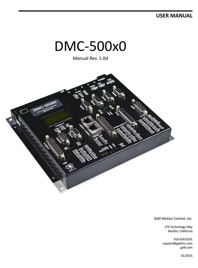
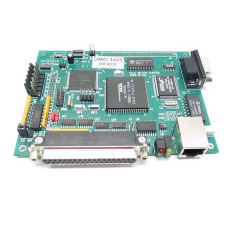
Galil Motion Control DMC-4040 User manual

USER MANUAL
DMC-40x0
Manual Rev. 1.0w
Galil Motion Control, Inc.
270 Technolog Wa
Rocklin, California
916.626.0101
galil.com
01/2017

Using This Manual
This user manual provides information for proper operation of the DMC-40x0 controller. A separate supplemental
manual, the Command Reference, contains a description of the commands available for use with this controller. It
is recommended that the user download the latest version of the Command Reference and User Manual from the
Galil Website.
http://www.galilmc.com/support/manuals.php
Your DMC-40x0 motion controller has been designed to work with both servo and stepper t pe motors.
Installation and s stem setup will var depending upon whether the controller will be used with stepper motors or
servo motors. To make finding the appropriate instructions faster and easier, icons will be next to an information
that applies exclusivel to one t pe of s stem. Otherwise, assume that the instructions appl to all t pes of
s stems. The icon legend is shown below.
Attention: Pertains to servo motor use.
Attention: Pertains to stepper motor use.
4080
Attention: Pertains to controllers with more than 4 axes.
Please note that man examples are written for the DMC-4040 four-axes controller or the DMC-4080 eight axes
controller. Users of the DMC-4030 3-axis controller, DMC-4020 2-axes controller or DMC-4010 1-axis controller
should note that the DMC-4030 uses the axes denoted as ABC, the DMC-4020 uses the axes denoted as AB, and the
DMC-4010 uses the A-axis onl .
Examples for the DMC-4080 denote the axes as A,B,C,D,E,F,G,H. Users of the DMC-4050 5-axes controller. DMC-
4060 6-axes controller or DMC-4070, 7-axes controller should note that the DMC-4050 denotes the axes as
A,B,C,D,E, the DMC-4060 denotes the axes as A,B,C,D,E,F and the DMC-4070 denotes the axes as A,B,C,D,E,F,G. The
axes A,B,C,D ma be used interchangeabl with X, Y, Z, W.
WARNING
Machiner in motion can be dangerous!
It is the responsibilit of the user to design effective error handling and safet protection as
part of the machiner . Galil shall not be liable or responsible for an incidental or
consequential damages
DMC-40x0 Contents ▫ i

Contents
Contents iii
Chapter 1 Overview 1
Introduction ................................................................................................................... 1
Part Numbers ................................................................................................................ 2
Overview of Motor Types ............................................................................................. 5
Overview of xternal Amplifiers .................................................................................. 6
Galil Internal Amplifiers and Drivers ........................................................................... 6
Functional lements ...................................................................................................... 7
Chapter 2 Getting Started 10
Layout ........................................................................................................................... 10
Power Connections ....................................................................................................... 12
Dimensions ................................................................................................................... 13
lements You Need ....................................................................................................... 15
Installing the DMC, Amplifiers, and Motors ................................................................ 16
Chapter 3 Connecting Hardware 33
Overview ....................................................................................................................... 33
Overview of Optoisolated Inputs .................................................................................. 33
Optoisolated Input lectrical Information .................................................................... 36
High Power Optoisolated Outputs ................................................................................ 39
TTL Inputs and Outputs ................................................................................................ 40
Analog Inputs ................................................................................................................ 42
xtended I/O ................................................................................................................. 42
xternal Amplifier Interface ......................................................................................... 43
Chapter 4 Software Tools and Communication 50
Introduction ................................................................................................................... 50
Controller Response to Commands .............................................................................. 50
Unsolicited Messages Generated by Controller ............................................................ 51
Serial Communication Ports ......................................................................................... 51
thernet Configuration .................................................................................................. 53
Modbus ......................................................................................................................... 55
Data Record .................................................................................................................. 58
GalilSuite (Windows and Linux) .................................................................................. 64
Creating Custom Software Interfaces ........................................................................... 65
Chapter 5 Command Basics 67
Introduction ................................................................................................................... 67
Command Syntax - ASCII ............................................................................................ 67
Controller Response to DATA ...................................................................................... 68
Interrogating the Controller .......................................................................................... 69
Chapter 6 Programming Motion 71
Overview ....................................................................................................................... 71
Independent Axis Positioning ....................................................................................... 72
Independent Jogging ..................................................................................................... 74
Position Tracking .......................................................................................................... 75
Linear Interpolation Mode ............................................................................................ 79
Vector Mode: Linear and Circular Interpolation Motion .............................................. 82
lectronic Gearing ........................................................................................................ 89
lectronic Cam .............................................................................................................. 92
PVT Mode ..................................................................................................................... 97
Contour Mode ............................................................................................................... 100
DMC-40x0 Contents ▫ ii

Virtual Axis ................................................................................................................... 104
Stepper Motor Operation .............................................................................................. 105
Stepper Position Maintenance Mode (SPM) ................................................................. 107
Dual Loop (Auxiliary ncoder) .................................................................................... 110
Motion Smoothing ....................................................................................................... 112
Homing ......................................................................................................................... 114
High Speed Position Capture (The Latch Function) .................................................... 116
Chapter 7 Application Programming 117
Overview ....................................................................................................................... 117
Program Format ............................................................................................................ 117
xecuting Programs - Multitasking .............................................................................. 119
Debugging Programs .................................................................................................... 120
Program Flow Commands ............................................................................................ 121
Mathematical and Functional xpressions ................................................................... 136
Variables ........................................................................................................................ 139
Operands ....................................................................................................................... 140
Arrays ............................................................................................................................ 141
Input of Data (Numeric and String) .............................................................................. 144
Output of Data (Numeric and String) ........................................................................... 146
Hardware I/O ................................................................................................................ 150
xtended I/O of the DMC-40x0 Controller .................................................................. 154
xample Applications ................................................................................................... 156
Using the DMC ditor to nter Programs .................................................................... 160
Chapter 8 Hardware & Software Protection 162
Introduction ................................................................................................................... 162
Hardware Protection ..................................................................................................... 162
Software Protection ....................................................................................................... 163
Chapter 9 Troubleshooting 167
Overview ....................................................................................................................... 167
Chapter 10 Theory of Operation 170
Overview ....................................................................................................................... 170
Operation of Closed-Loop Systems .............................................................................. 172
System Modeling .......................................................................................................... 173
System Analysis ............................................................................................................ 177
System Design and Compensation ................................................................................ 179
Appendices 182
lectrical Specifications ................................................................................................ 182
Performance Specifications .......................................................................................... 184
Ordering Options .......................................................................................................... 185
Power Connector Part Numbers .................................................................................... 192
Input Current Limitations ............................................................................................. 193
Serial Cable Connections .............................................................................................. 194
Configuring the Amplifier nable Circuit .................................................................... 196
Signal Descriptions ....................................................................................................... 206
List of Other Publications ............................................................................................. 208
Training Seminars ......................................................................................................... 208
Contacting Us ................................................................................................................ 209
WARRANTY ................................................................................................................ 210
Integrated Components 211
Overview ....................................................................................................................... 211
A1 – AMP-430x0 (-D3040,-D3020) 213
Description .................................................................................................................... 213
lectrical Specifications ................................................................................................ 214
Operation ....................................................................................................................... 215
rror Monitoring and Protection ................................................................................... 217
DMC-40x0 Contents ▫ iii
A2 – AMP-43140 (-D3140) 219
Description .................................................................................................................... 219
lectrical Specifications ................................................................................................ 220
Operation ....................................................................................................................... 221
A3 – AMP-43240 (-D3240) 222
Description .................................................................................................................... 222
lectrical Specifications ................................................................................................ 223
Operation ....................................................................................................................... 224
rror Monitoring and Protection ................................................................................... 225
A4 – AMP-435x0 (-D3540,-D3520) 228
Description .................................................................................................................... 228
lectrical Specifications ................................................................................................ 229
Operation ....................................................................................................................... 230
rror Monitoring and Protection ................................................................................... 233
A5 – AMP-43640 (-D3640) 235
Introduction ................................................................................................................... 235
lectrical Specifications ................................................................................................ 236
Operation ....................................................................................................................... 238
A6 – AMP-43740 (-D3740) 241
Description .................................................................................................................... 241
lectrical Specifications ................................................................................................ 242
Operation ....................................................................................................................... 243
rror Monitoring and Protection ................................................................................... 245
A7 – SDM-440x0 (-D4040,-D4020) 247
Description .................................................................................................................... 247
lectrical Specifications ................................................................................................ 248
Operation ....................................................................................................................... 249
A8 – SDM-44140 (-D4140) 251
Description .................................................................................................................... 251
lectrical Specifications ................................................................................................ 252
Operation ....................................................................................................................... 253
rror Monitoring and Protection ................................................................................... 254
A9 – CMB-41012 (-C012) 255
Description .................................................................................................................... 255
Connectors for CMB-41012 Interconnect Board ......................................................... 256
A10 – CMB-41022 (-C022) 259
Description .................................................................................................................... 259
Connectors for CMB-41022 Interconnect Board ......................................................... 260
A11 – ICM-42000 (-I000) 264
Description .................................................................................................................... 264
Connectors for ICM-42000 Interconnect Board ........................................................... 265
A12 – ICM-42100 (-I100) 268
Description .................................................................................................................... 268
Connectors for ICM-42100 Interconnect Board ........................................................... 269
Theory of Operation ...................................................................................................... 272
A13 – ICM-42200 (-I200) 275
Description .................................................................................................................... 275
Connectors for ICM-42200 Interconnect Board ........................................................... 276
DMC-40x0 Contents ▫ iv

Chapter 1 Overview
Intro uction
The DMC-40x0 Series are Galil’s highest performance stand-alone controller. The controller series offers man
enhanced features including high speed communications, non-volatile program memor , faster encoder speeds,
and improved cabling for EMI reduction.
Each DMC-40x0 provides two communication channels: high speed RS-232 (2 channels up to 115K Baud) and 100
BaseT Ethernet. The controllers allow for high-speed servo control up to 22 million encoder counts/sec and step
motor control up to 6 million steps per second. Sample rates as low as 31.25 µsec per axis are available.
A Flash EEPROM provides non-volatile memor for storing application programs, parameters, arra s and firmware.
New firmware revisions are easil upgraded in the field.
The DMC-40x0 is available with up to eight axes in a single stand alone unit. The DMC-4010, 4020, 4030, 4040 are
one thru four axes controllers and the DMC-4050, 4060, 4070, 4080 are five thru eight axes controllers. All eight
axes have the abilit to use Galil’s integrated amplifiers or drivers and connections for integrating external devices.
Designed to solve complex motion problems, the DMC-40x0 can be used for applications involving jogging, point-
to-point positioning, vector positioning, electronic gearing, multiple move sequences, contouring and a PVT Mode.
The controller eliminates jerk b programmable acceleration and deceleration with profile smoothing. For smooth
following of complex contours, the DMC-40x0 provides continuous vector feed of an infinite number of linear and
arc segments. The controller also features electronic gearing with multiple master axes as well as gantr mode
operation.
For s nchronization with outside events, the DMC-40x0 provides uncommitted I/O, including 8 optoisolated digital
inputs (16 inputs for DMC-4050 thru DMC-4080), 8 high power opticall isolated outputs (16 outputs for DMC-4050
thru DMC-4080), and 8 analog inputs for interface to jo sticks, sensors, and pressure transducers. The DMC-40x0
also has an additional 32 I/O at 3.3V logic. Further I/O is available if the auxiliar encoders are not being used (2
inputs / each axis). Dedicated optoisolated inputs are provided for forward and reverse limits, abort, home, and
definable input interrupts.
Commands are sent in ASCII. Additional software is available for automatic-tuning, trajector viewing on a PC
screen, and program development using man environments such as Visual Basic, C, C++ etc. Drivers for Windows
XP, Vista and 7 (32 & 64 bit) as well as Linux are available.
Chapter 1 Overview ▫ 1 DMC-40x0 User Manual

Part Numbers
The DMC-40x0 is modular b nature, meaning that a customer must specif several components in order to create
a full part number. The user must specif the main control board (DMC), the communication board (CMB), and the
interconnect module (ICM) to have a complete unit. The user can also specif an optional internal amplifier (AMP
or SDM). How these models stack up internall is shown in Figure 1.1 for 1-4 axis models.
For 5-8 axis models, the user must also specif an additional ICM and optional internal amplifier t pe for axis 5-8 as
shown in Figure 1.2.
Each module has it's own set of part numbers and configuration options that make the full part number of a DMC-
40x0 unit. The DMC has the part number format “DMC-40X0(Y),” the CMB is “-CXXX(Y),” the ICM is “-IXXX(Y),” and
the AMP/SDM is “-DXXX(Y),” where X designates different module options and Y designates different configuration
options for these modules. The full DMC-40x0 part number would be the full string of individual module part
numbers combined as shown for 1-4 and 5-8 axis models in Figure 1.3.
Chapter 1 Overview ▫ 2 DMC-40x0 User Manual
Figure 1.1: Abstract internal layout of the DMC-40x0 for 1-4 axis models
Figure 1. : Abstract internal layout of the DMC-40x0 for 5-8 axis models

The placement of ICM and AMP/SDM options is extremel important for 5-8 axis models. Reading left to right, the
first ICM (Axis 1-4) will be placed in the ICM (1) spot in Figure 1.2 and the second ICM (Axis 5-8) will be placed in
the ICM (2) spot. This also follows for AMP/SDM placement.
If the part number is not readil available, ou can determine the information b using the 'ID' command. Issuing
an 'ID' command when connected to the controller will return our controller's internal hardware configuration.
WARNING
The CMB an ICM mo ule options effect the pin-outs of the DMC-40x0.
Use Table 1.2 and Table 1.3 below to determine our CMB and ICM part numbers then refer to the
appropriate documentation for our pin-outs before connecting an hardware.
DMC, “DMC-40X0(Y)” Options
Option Type Options Brief Description Documentation
X 1,2,3,4,5,6,7, and 8 Number of control axis N/A
Y DIN DIN Rail Mount DMC, “DMC-40X0(Y)” Controller Board
Options, starting on pg 185.
12V Power Controller with 12 VDC
-16bit 16-bit analog inputs
4-20mA 4-20mA analog inputs
ISCNTL Isolate Controller Power
TRES Encoder terminating resistors
ETL ETL certification
MO Motor off jumper installed
Table 1.1: Controller board, DMC, “DMC-40X0(Y)” options
Chapter 1 Overview ▫ 3 DMC-40x0 User Manual
Figure 1.3: Layout of a complete DMC-40x0 part number

CMB, “-CXXX(Y)” Options
Option Type Options Brief Description Documentation
XXX 012 Default communication board A9 – CMB-41012 (-C012), pg 255
022 Dual-Ethernet communication board A10 – CMB-41022 (-C022), pg 259
Y 5V SSI Feedback 5V – Configure Extended I/O for 5V logic, pg
187
P422 RS-422 on Main and Aux serial port RS-422 – Serial Port Serial Communication, pg
187
P1422 RS-422 on Main serial port onl
P2422 RS-422 on Aux serial port onl
Table 1. : Communication board, CMB “-CXXX(Y)” options
ICM, “-IXXX(Y)” Options
Option Type Options Brief Description Documentation
XXX 000 Default interconnect board A11 – ICM-42000 (-I000), pg 264
100 Sine/Cosine feedback interconnect board A12 – ICM-42100 (-I100), pg 268
200 26-pin encoder connecter interconnect board A13 – ICM-42200 (-I200),pg 275
Y SSI SSI Feedback ICM, “-IXXX(Y)” Interconnect Board Options,
starting on pg 188
BiSS BiSS Feedback
DIFF Differential ±10 motor command outputs
STEP Differential STEP/DIR outputs
Table 1.3: Interconnect module, ICM “-IXXX(Y)” options
AMP/SDM, “-DXXXX(Y)” Options
Option Type Options Brief Description Documentation
XXXX 3020/3040 500 W trapazoidal servo drive
2 and 4-axis models A1 – AMP-430x0 (-D3040,-D3020), pg 213
3140 20 W brush-t pe onl drive A2 – AMP-43140 (-D3140), pg 219
3240 750 W trapazoidal servo drive A3 – AMP-43240 (-D3240), pg 222
3520/3540 600 W sinusoidal servo drive
2 and 4-axis models A4 – AMP-435x0 (-D3540,-D3520), pg 228
3640 20 W sinusoidal servo drive A5 – AMP-43640 (-D3640), pg 235
4040/4020 1.4 A with 1/16 microstepping drive A7 – SDM-440x0 (-D4040,-D4020), pg 247
4140 3 A with 1/64 microstepping drive A8 – SDM-44140 (-D4140), pg 251
Y 100mA 100mA current
-D3140 option onl
AMP/SDM, “-DXXXX(Y)” Internal Amplifier Options,
starting on pg 190
1 Not available for all amplifier options, see the
proper documentation in Ordering Options.
SSR Solid state rela 1
HALLF Filtered hall sensors1
ISAMP Isolates power between amplifiers
Two banks of AMP/SDMs required
Table 1.4: Amplifier options, AMP/SDM “-DXXXX(Y)”
Chapter 1 Overview ▫ 4 DMC-40x0 User Manual

Overview of Motor Types
The DMC-40x0 can provide the following t pes of motor control:
1. Standard servo motors with ± 10 volt command signals
2. Brushless servo motors with sinusoidal commutation
3. Step motors with step and direction signals
4. Other actuators such as h draulics and ceramic motors - For more information, contact Galil.
The user can configure each axis for an combination of motor t pes, providing maximum flexibilit .
Stan ar Servo Motor with ±10 Volt Comman Signal
The DMC-40x0 achieves superior precision through use of a 16-Bit motor command output DAC and a sophisticated
PID filter that features velocit and acceleration feed-forward, an extra pole filter and integration limits.
The controller is configured b the factor for standard servo motor operation. In this configuration, the controller
provides an analog signal (±10 volts) to connect to a servo amplifier. This connection is described in Chapter 2.
Brushless Servo Motor with Sinusoi al Commutation
The DMC-40x0 can provide sinusoidal commutation for brushless motors (BLM). In this configuration, the
controller generates two sinusoidal signals for connection with amplifiers specificall designed for this purpose.
Note: The task of generating sinusoidal commutation ma be accomplished in the brushless motor amplifier. If the
amplifier generates the sinusoidal commutation signals, onl a single command signal is required and the controller
should be configured for a standard servo motor (described above).
Sinusoidal commutation in the controller can be used with linear and rotar BLMs. However, the motor velocit
should be limited such that a magnetic c cle lasts at least 6 milliseconds with a standard update rate of 1
millisecond. For faster motors, please contact the factor .
To simplif the wiring, the controller provides a one-time, automatic set-up procedure. When the controller has
been properl configured, the brushless motor parameters ma be saved in non-volatile memor .
The DMC-40x0 can control BLMs equipped with Hall sensors as well as without Hall sensors. If Hall sensors are
available, once the controller has been setup, the brushless motor parameters ma be saved in non-volatile
memor . In this case, the controller will automaticall estimate the commutation phase upon reset. This allows
the motor to function immediatel upon power up. The Hall effect sensors also provide a method for setting the
precise commutation phase. Chapter 2 describes the proper connection and procedure for using sinusoidal
commutation of brushless motors.
Stepper Motor with Step an Direction Signals
The DMC-40x0 can control stepper motors. In this mode, the controller provides two signals to
connect to the stepper motor: Step and Direction. For stepper motor operation, the controller does
not require an encoder and operates the stepper motor in an open loop fashion. Chapter 2 describes
the proper connection and procedure for using stepper motors.
If encoders are available on the stepper motor, Galil’s Stepper Position Maintenance Mode ma be
used for automatic monitoring and correction of the stepper position. See Stepper Position
Maintenance Mode (SPM) in Chapter 6 for more information.
Chapter 1 Overview ▫ 5 DMC-40x0 User Manual

Overview of External Amplifiers
The amplifiers should be suitable for the motor and ma be linear or pulse-width-modulated. An amplifier ma
have current feedback, voltage feedback or velocit feedback.
Amplifiers in Current Mo e
Amplifiers in current mode should accept an analog command signal in the ±10 volt range. The amplifier gain
should be set such that a +10V command will generate the maximum required current. For example, if the motor
peak current is 10A, the amplifier gain should be 1 A/V.
Amplifiers in Velocity Mo e
For velocit mode amplifiers, a command signal of 10 volts should run the motor at the maximum required speed.
The velocit gain should be set such that an input signal of 10V runs the motor at the maximum required speed.
Stepper Motor Amplifiers
For step motors, the amplifiers should accept step and direction signals.
Galil Internal Amplifiers an Drivers
With the DMC-40x0 Galil offers a variet of Servo Amplifiers and Stepper Drivers that are integrated into the same
enclosure as the controller. Using the Galil Amplifiers and Drivers provides a simple straightforward motion control
solution in one box. Instead of having to route a +/-10V motor command signal, or STEP/DIR to some external box,
all the wiring is taken care of internall . In addition, Galil's internal amplifiers reside inside the same box as the
controller, ICM, and communication board (see Part Numbers, pg 2) saving real estate space and the hassle of
configuring a separate device.
A full list of amplifier specifications and details can be found in the Integrated Components, starting on pg 211.
Chapter 1 Overview ▫ 6 DMC-40x0 User Manual

Functional Elements
The DMC-40x0 circuitr can be divided into the following functional groups as shown in Figure 1.4 and discussed
below.
Figure 1.4: DMC-40x0 Functional Elements
Microcomputer Section
The main processing unit of the controller is a specialized Microcomputer with RAM and Flash EEPROM. The RAM
provides memor for variables, arra elements, and application programs. The flash EEPROM provides non-volatile
storage of variables, programs, and arra s. The Flash also contains the firmware of the controller, which is field
upgradeable.
Motor Interface
Galil’s GL-1800 custom, sub-micron gate arra performs quadrature decoding of each encoder at up to 22 MHz. For
standard servo operation, the controller generates a ±10 volt analog signal (16-bit DAC). For sinusoidal
commutation operation, the controller uses two DACs to generate two ±10 volt analog signals. For stepper motor
operation, the controller generates a step and direction signal.
Communication
The communication interface with the DMC-40x0 consists of high speed RS-232 and Ethernet. The Ethernet is
10/100Bt and the two RS-232 channels can generate up to 115K. An additional Ethernet port is available with the
CMB-41022, see A10 – CMB-41022 (-C022), pg 259 for details.
General I/O
The DMC-40x0 provides interface circuitr for 8 bi-directional, optoisolated inputs, 8 high power optoisolated
outputs and 8 analog inputs with 12-Bit ADC (16-Bit optional). The DMC-40x0 also has an additional 32 I/O (3.3V
Chapter 1 Overview ▫ 7 DMC-40x0 User Manual
WATCHDOG TIM R
RISC BAS D
MICROCOMPUT R
HIGH-SP D
MOTOR/ NCOD R
INT RFAC
FOR
A,B,C,D
I/O INT RFAC
TH RN T
RS-232 /
RS-422
8 UNCOMMITT D
ANALOG INPUTS
HIGH-SP D LATCH FOR ACH AXIS
ISOLAT D LIMITS AND
HOM INPUTS
MAIN NCOD RS
AUXILIARY NCOD RS
+/- 10 VOLT OUTPUT FOR
S RVO MOTORS
PULS /DIR CTION OUTPUT
FOR ST P MOTORS
HIGH SP D NCOD R
COMPAR OUTPUT
8 PROGRAMMABL ,
OPTOISOLAT D
INPUTS
8 PROGRAMMABL
HIGH POW R OPTOISOLAT D
OUTPUTS
32 Configurable I/O

logic) and unused auxiliar encoder inputs ma also be used as additional inputs (2 inputs / each axis). The general
inputs as well as the index pulse can also be used as high speed latches for each axis. A high speed encoder
compare output is also provided.
4080
The DMC-4050 through DMC-4080 controller provides an additional 8 optoisolated inputs and 8 high
power optoisolated outputs.
System Elements
As shown in Figure 1.5, the DMC-40x0 is part of a motion control s stem which includes amplifiers, motors and
encoders. These elements are described below.
Figure 1.5: Elements of Servo systems
Motor
A motor converts current into torque which produces motion. Each axis of motion requires a motor sized properl
to move the load at the required speed and acceleration. (Galil’s MotorSizer Web tool can help ou with motor
sizing: www.galilmc.com/support/motorsizer)
The motor ma be a step or servo motor and can be brush-t pe or brushless, rotar or linear. For step motors, the
controller can be configured to control full-step, half-step, or microstep drives. An encoder is not required when
step motors are used.
Other motors and devices such as Ultrasonic Ceramic motors and voice coils can be controlled with the DMC-40x0.
Amplifier (Driver)
For each axis, the power amplifier converts a ±10 volt signal from the controller into current to drive the motor.
For stepper motors, the amplifier converts step and direction signals into current. The amplifier should be sized
properl to meet the power requirements of the motor. For brushless motors, an amplifier that provides electronic
commutation is required or the controller must be configured to provide sinusoidal commutation. The amplifiers
ma be either pulse-width-modulated (PWM) or linear. The ma also be configured for operation with or without
a tachometer. For current amplifiers, the amplifier gain should be set such that a 10 volt command generates the
maximum required current. For example, if the motor peak current is 10A, the amplifier gain should be 1 A/V. For
velocit mode amplifiers, 10 volts should run the motor at the maximum speed.
Galil offers amplifiers that are integrated into the same enclosure as the DMC-40x0. See the Integrated section in
the Appendices or http://galilmc.com/products/accelera/dmc40x0.html for more information.
Chapter 1 Overview ▫ 8 DMC-40x0 User Manual
Computer DMC-40x0 Controller Amplifier (Driver)
Power Supply
Encoder Motor

Enco er
An encoder translates motion into electrical pulses which are fed back into the controller. The DMC-40x0 accepts
feedback from either a rotar or linear encoder. T pical encoders provide two channels in quadrature, known as
MA and MB. This t pe of encoder is known as a quadrature encoder. Quadrature encoders ma be either single-
ended (MA+ and MB+) or differential (MA+, MA-, MB+, and MB-). The DMC-40x0 decodes either t pe into
quadrature states or four times the number of c cles. Encoders ma also have a third channel (or index) for
s nchronization.
The DMC-40x0 can be ordered with 120 Ω termination resistors installed on the encoder inputs. See the Ordering
Options in the Appendix for more information.
The DMC-40x0 can also interface to encoders with pulse and direction signals. Refer to the “CE” command in the
command reference for details.
There is no limit on encoder line densit ; however, the input frequenc to the controller must not exceed 5,500,000
full encoder c cles/second (22,000,000 quadrature counts/sec). For example, if the encoder line densit is 10,000
c cles per inch, the maximum speed is 550 inches/second. If higher encoder frequenc is required, please consult
the factor .
The standard encoder voltage level is TTL (0-5v), however, voltage levels up to 12 Volts are acceptable. (If using
differential signals, 12 Volts can be input directl to the DMC-40x0. Single-ended 12 Volt signals require a bias
voltage input to the complementar inputs).
The DMC-40x0 can accept analog feedback (±10v) instead of an encoder for an axis. For more information see the
command AF in the command reference.
To interface with other t pes of position sensors such as absolute encoders, Galil can customize the controller and
command set. Please contact Galil to talk to one of our applications engineers about our particular s stem
requirements.
Sinusoi al Enco ers
The DMC-40x0 can be ordered with an interconnect module that supports the use of 1Vp-p sinusoidal encoders.
This interconnect module is the ICM-42100. See A12 – ICM-42100 (-I100) in the Appendix for more information.
Watch Dog Timer
The DMC-40x0 provides an internal watch dog timer which checks for proper microprocessor operation. The timer
toggles the Amplifier Enable Output (AMPEN) which can be used to switch the amplifiers off in the event of a
serious DMC-40x0 failure. The AMPEN output is normall high. During power-up and if the microprocessor ceases
to function properl , the AMPEN output will go low. The error light will also turn on at this stage. A reset is
required to restore the DMC-40x0 to normal operation. Consult the factor for a Return Materials Authorization
(RMA) Number if our DMC-40x0 is damaged.
Chapter 1 Overview ▫ 9 DMC-40x0 User Manual

Chapter 2 Getting Starte
Layout
The following la outs assume either an ICM-42000(I000) or ICM-42100(I100) interconnect modules are installed.
For la outs of s stems with ICM-42200’s(I200) installed please contact Galil. Overall dimensions and footprint are
identical, the onl differences are in connector t pe and location.
DMC-4040
Figure .1: Outline of the of the DMC-40x0 1-4 axes model
Chapter 2 Getting Started ▫ 10 DMC-40x0 User Manual

DMC-4080
Figure . : Outline of the of the DMC-40x0, 5-8 axes model
Chapter 2 Getting Started ▫ 11 DMC-40x0 User Manual

Power Connections
Figure .3: Power Connector locations for the DMC-40x0
Figure .4: Power Connector used when controller is ordered without Galil Amplifiers
For more information on powering our controller see Step 4. Power the Controller, pg 17. For more information
regarding connector t pe and part numbers see Power Connector Part Numbers, pg 192. The power specifications
for the controller are provided in Power Requirements, pg 183. and the power specifications for each amplifier are
found under their specific section in the appendix, see Integrated Components, pg 211.
Chapter 2 Getting Started ▫ 12 DMC-40x0 User Manual
SDM/AMP Power
Axis E-H
SDM/AMP Power
Axis A-D
2-pin Molex controller power connector.

Dimensions
DMC-4040
Figure .5: Dimensions (in inches) of DMC-40x0 (where x= 1, , 3, or 4 axis)
Chapter 2 Getting Started ▫ 13 DMC-40x0 User Manual

DMC-4080
Figure .6: Dimensions (in inches) of DMC-40x0 (where x= 5, 6, 7, or 8 axis)
Chapter 2 Getting Started ▫ 14 DMC-40x0 User Manual

Elements You Nee
For a complete s stem, Galil recommends the following elements:
1. DMC-40x0, motion controller where the x designates number of axis, 1-8.
2. Motor Amplifiers (Integrated when using Galil amplifiers and drivers)
3. Power Suppl for Amplifiers and controller
4. Brush or Brushless Servo motors with Optical Encoders or stepper motors.
a. Cables for connecting to the DMC-40x0’s integrated ICM’s.
5. PC (Personal Computer - RS232 or Ethernet for DMC-40x0)
6. GalilSuite or GalilSuite Lite (Free) software package
GalilSuite is highl recommended for first time users of the DMC-40x0. It provides step-b -step instructions for
s stem connection, tuning, and anal sis.
Chapter 2 Getting Started ▫ 15 DMC-40x0 User Manual
This manual suits for next models
1
Table of contents
Other Galil Motion Control Controllers manuals

Galil Motion Control
Galil Motion Control DMC-18 2 Series User manual

Galil Motion Control
Galil Motion Control RIO-47 seriesRIO-47100 User manual

Galil Motion Control
Galil Motion Control DMC-14 5 Series User manual

Galil Motion Control
Galil Motion Control DMC-1600 Series User manual

Galil Motion Control
Galil Motion Control DMC-500 Series User manual

Galil Motion Control
Galil Motion Control DMC-42 0 Series User manual

Galil Motion Control
Galil Motion Control DMC-1000 User manual

Galil Motion Control
Galil Motion Control RIO-47120 User manual

Galil Motion Control
Galil Motion Control DMC-40x0 Series Installation manual