Helena Laboratories Actalyke XL User manual
Actalyke®XL
Activated Clotting Time Test System
Operator’s Manual
Catalog Number 5770, 110-220 VAC, 50-60 Hz

Actalyke®XL
Activated Clotting Time Test System
Operator’s Manual

WARNING!
DO NOT ATTEMPT TO MOVE, INSTALL, OR
OPERATE THIS INSTRUMENT BEFORE READING
AND UNDERSTANDING THE CONTENTS OF THIS
MANUAL, PARTICULARLY THE PRECAUTIONS,
LIMITATIONS AND HAZARDS IN SECTIONS
THREE AND FOUR.
Actalyke XL Program License Agreement
This copy of the Actalyke XL program is sold on the condition that the purchaser agrees to the
terms of this license agreement. If not, the purchaser should return the unopened diskette
package to Helena Laboratories to obtain a refund. Retention of the product will constitute
acceptance of this license.
1. Helena Laboratories Corp. (Helena) warrants to the ORIGINAL PURCHASER ONLY
(Purchaser) that the diskette on which the computer program is contained shall be free of
defects in materials and workmanship under normal use for 6 months from the date of pur-
chase. Helena will repair or, at its option, replace any defective diskette returned to the
address below during the 6-month period.
2. THIS IS THE ONLY WARRANTY MADE BY HELENA COVERING THE ACTALYKE XL
PROGRAM. THE COMPUTER PROGRAM AND THE ENCLOSED INSTRUCTIONAL
MATERIALS ARE SOLD “AS IS”, WITHOUT ANY WARRANTY OF ANY KIND, EXPRESSED
OR IMPLIED, INCLUDING BUT NOT LIMITED TO: ANY WARRANTY OF PERFORMANCE,
MERCHANTABILITY, OR FITNESS FOR A PARTICULAR PURPOSE. PURCHASER
ASSUMES ALL RISKS AS TO THE PERFORMANCE AND RESULTS OF THE PROGRAM.
IN NO EVENT WILL HELENA OR, ITS SUPPLIERS BE LIABLE FOR ANY INCIDENTAL,
CONSEQUENTIAL OR OTHER DAMAGES, INCLUDING BUT NOT LIMITED TO ANY
DAMAGES ARISING FROM USE OR MISUSE OF THE PROGRAM.
3. This computer program is for the use of purchaser only, and only on the computer system
specified. No part of the program may be reproduced, nor may any part of the program be
utilized in or transferred to any information storage and retrieval system of electronic or
mechanical medium without prior written permission of Helena. Purchaser may make up to
two back-up copies of the program for Purchaser’s personal use only, and should forward any
questions concerning reproduction or transfer of the program, and requests for permission to
do so, to Helena Laboratories, P.O. Box 752, Beaumont, TX 77704-0752. Any noncompliance
with this paragraph will result in termination of this license, and may also result in legal liability
under U.S. copyright laws.
4. Use of this program constitutes acceptance of the terms and conditions of this agreement.
©October, 1999 Helena Laboratories
Helena Laboratories 1530 Lindbergh Dr. P.O. Box 752
Beaumont, Texas 77704
Telephone (409) 842-3714

ACTALYKE XL Table of Contents
-i-
List of Sections
Section 1 - Instrument Use and Function............................................................................1-1
Section 2 - Principles of Operation......................................................................................2-1
Section 3 - Precautions and Limitations.............................................................................3-1
Section 4 - Hazards...............................................................................................................4-1
Section 5 - Installation Instruction.......................................................................................5-1
5.1. Unpacking and Inspection ............................................................................................5-1
5.2. Installation ....................................................................................................................5-1
5.3. Verification of Functionality...........................................................................................5-2
Section 6 - Setup...................................................................................................................6-1
6.1. Interface Parameters ....................................................................................................6-1
6.1.1. Keypad...................................................................................................................6-1
6.1.2. Time and Date........................................................................................................6-1
6.1.2.1. Date Format.....................................................................................................6-2
6.1.2.2. Date.................................................................................................................6-2
6.1.2.3. Time.................................................................................................................6-2
6.1.3. Sound.....................................................................................................................6-3
6.1.4. Backlight.................................................................................................................6-3
6.1.5. Printer ....................................................................................................................6-3
6.1.5.1. Contrast ...........................................................................................................6-4
6.1.5.2. Header/Footer .................................................................................................6-4
6.1.6. Export.....................................................................................................................6-4
6.1.6.1. Export Parameters...........................................................................................6-5
6.1.7. Spreadsheet...........................................................................................................6-5
6.1.7.1. Spreadsheet Parameters.................................................................................6-5
6.1.8. System Timers .......................................................................................................6-6
6.1.8.1. System Shutdown............................................................................................6-6
6.1.8.2. Operator ID Entry ............................................................................................6-6
6.2. General Parameters .....................................................................................................6-7
6.2.1. Operator ID/Passwords..........................................................................................6-7
6.2.1.1. Enter/Edit Operator ID/Passwords...................................................................6-7
6.2.1.2. Delete Operator ID/Passwords ........................................................................6-8
6.2.1.3. Archive and Retrieve Operator IDs..................................................................6-8
6.2.2. Patient....................................................................................................................6-9
6.2.3. Test ......................................................................................................................6-10
6.2.4. QC (Bio) ...............................................................................................................6-11
6.2.4.1. QC Levels Which Must Pass .........................................................................6-11
6.2.4.2. Set QC Schedule...........................................................................................6-11
6.2.4.3. C-ACT, K-ACT, G-ACT, and MAX-ACT.........................................................6-12
6.2.5. ECT......................................................................................................................6-12
6.2.5.1. ECT Levels Which Must Pass .......................................................................6-13
6.2.5.2. Set ECT Schedule .........................................................................................6-13
6.2.6. Auto Output ..........................................................................................................6-13
6.3. Paper Feed.................................................................................................................6-14

ACTALYKE XL Table of Contents
-ii-
6.4. Archive........................................................................................................................6-14
6.4.1. Save Parameters .................................................................................................6-14
6.4.2. Restore Parameters .............................................................................................6-15
6.4.3. Print Setup Parameters........................................................................................6-15
6.4.4. Save Operator IDs ...............................................................................................6-18
6.4.5. Restore Operator IDs ...........................................................................................6-18
6.4.6. Print Operator ID List ...........................................................................................6-19
6.5. Maintenance ...............................................................................................................6-19
Section 7 - Operating Instructions.......................................................................................7-1
7.1. Instructions for Clotting Time Tests ..............................................................................7-1
7.1.1. Pre-warm................................................................................................................7-1
7.1.2. Run Test.................................................................................................................7-1
7.1.2.1. Patient ID/Patient Demographics.....................................................................7-3
7.1.2.1.1. Well Number .............................................................................................7-3
7.1.2.1.2. Patient ID & Test.......................................................................................7-3
7.1.2.1.3. Sex............................................................................................................7-4
7.1.2.1.4. Height........................................................................................................7-4
7.1.2.1.5. Weight.......................................................................................................7-5
7.1.2.1.6. Clear ACT Points ......................................................................................7-5
7.1.2.1.7. Heparin Dosage Documentation ...............................................................7-6
7.1.2.2. Test..................................................................................................................7-6
7.1.3. View Chart..............................................................................................................7-6
7.1.4. Change Operator ...................................................................................................7-7
7.2. To Abort Operation .......................................................................................................7-7
7.3. Results..........................................................................................................................7-7
7.4. Battery ..........................................................................................................................7-8
7.4.1. Battery Charge .......................................................................................................7-8
7.4.2. Battery Conservation..............................................................................................7-8
7.4.3. Battery Usage ........................................................................................................7-8
7.5. Operator ID...................................................................................................................7-9
7.6. Software Installation .....................................................................................................7-9
Section 8 - Test Functions and Quality Control..................................................................8-1
8.1. QC ................................................................................................................................8-1
8.1.1. Run ECT Self Check (Clotting Time Check)...........................................................8-1
8.1.2. Run Biological QC Test (QC of Individual Coagulation Assays).............................8-1
8.1.3. View/Output View Chart (Levey-Jennings Chart) ...................................................8-2
8.1.4. Delete Complete QC Test Data..............................................................................8-3
8.1.5. Delete Single QC Clot Point ...................................................................................8-3
8.1.6. Temperature QC (Test Well Temperature Check) .................................................8-4
Section 9 - Performance Specifications..............................................................................9-1
9.1. Instrument Performance Specifications ........................................................................9-1
9.2. System Performance Characteristics............................................................................9-1
9.2.1. MAX-ACT ...............................................................................................................9-1
9.2.2. C-ACT, K-ACT and G-ACT ....................................................................................9-2

ACTALYKE XL Table of Contents
-iii-
Section 10 - Maintenance, Troubleshooting, Warranty....................................................10-1
10.1. Maintenance .............................................................................................................10-1
10.1.1. Instrument Cleaning ...........................................................................................10-1
10.1.2. Clotting Time Check...........................................................................................10-1
10.1.3. Test Well Temperature Check............................................................................10-2
10.1.4. Test Well Cleaning .............................................................................................10-2
10.1.5. Printer Paper Replacement ................................................................................10-2
10.1.6. Fuse Replacement .............................................................................................10-2
10.1.7. Mag Sensor Calibration......................................................................................10-3
10.1.8. Drain Battery ......................................................................................................10-3
10.1.9. Battery Replacement..........................................................................................10-4
10.1.10. Touch Panel Calibration ...................................................................................10-5
10.2. Troubleshooting........................................................................................................10-8
10.3. Warranty .................................................................................................................10-12
10.4. Regulatory Information ...........................................................................................10-12
Section 11 - Symbology......................................................................................................11-1
Section 12 - Communication Specifications.....................................................................12-1
Section 13 - Menu Flowchart..............................................................................................13-1
Section 14 - Index................................................................................................................14-1
List of Figures
Figure 1-1. ACTALYKE XL.....................................................................................................1-2
Figure 2-1. Block Diagram......................................................................................................2-2
Figure 5-1. Actalyke XL, front view.........................................................................................5-3
Figure 5-2. Actalyke XL, rear view..........................................................................................5-3
Figure 5-3. Actalyke XL, top view...........................................................................................5-4
Figure 5-4. Actalyke XL, top view with paper .........................................................................5-4
Figure 5-5. Actalyke XL, left side view....................................................................................5-5
Figure 5-6. Actalyke XL, left side view....................................................................................5-5
Figure 5-7. Actalyke XL, right side view .................................................................................5-6
Figure 6-1. Enter Operator ID Screen* .................................................................................6-20
Figure 6-2. Run Test Screen ................................................................................................6-20
Figure 6-3. Setup Screen .....................................................................................................6-20
Figure 6-4. Setup Interface Parameters Screen...................................................................6-20
Figure 6-5. Select Preferred Keypad Screen........................................................................6-21
Figure 6-6. Setup Time & Date Screen ................................................................................6-21
Figure 6-7. Set Date Format Screen ....................................................................................6-21
Figure 6-8. Set Date Screen* ...............................................................................................6-21
Figure 6-9. Set Time Screen*...............................................................................................6-22
Figure 6-10. Setup Sound Screen........................................................................................6-22
Figure 6-11. Set Backlight Screen........................................................................................6-22
Figure 6-12. Setup Printer Screen........................................................................................6-22
Figure 6-13. Printer Contrast Adjustment Screen.................................................................6-23
Figure 6-14. Setup Export Parameters Screen ....................................................................6-23
Figure 6-15. Set Spreadsheet Parameters Screen ..............................................................6-23
Figure 6-16. Select Shutdown Time-out Screen...................................................................6-23

ACTALYKE XL Table of Contents
-iv-
Figure 6-17. Select Operator ID Time-out Screen................................................................6-24
Figure 6-18. General Parameters Screen ............................................................................6-24
Figure 6-19. Enter Operator ID List Screen* ........................................................................6-24
Figure 6-20. Passwords Screen*..........................................................................................6-24
Figure 6-21. Select Editable Demographics Screen.............................................................6-25
Figure 6-22. Setup Test Parameters Screen........................................................................6-25
Figure 6-23. ACT Timing Sequence Screen* .......................................................................6-25
Figure 6-24. ACT Test Range Limits Screen* ......................................................................6-25
Figure 6-25. Setup QC Screen.............................................................................................6-26
Figure 6-26. QC Schedule Screen*......................................................................................6-26
Figure 6-27. QC Lot Numbers Screen..................................................................................6-26
Figure 6-28. Enter Lot Numbers Screen* .............................................................................6-26
Figure 6-29. QC Mean and Range Screen...........................................................................6-27
Figure 6-30. Enter Lower/Upper Limit Screen*.....................................................................6-27
Figure 6-31. Setup ECT screen............................................................................................6-27
Figure 6-32. ECT Schedule screen*.....................................................................................6-27
Figure 6-33. Setup Automatic Output Screen.......................................................................6-28
Figure 6-34. Save/Restore/Print Screen...............................................................................6-28
Figure 7-1. Enter Operator ID Screen* .................................................................................7-10
Figure 7-2. Run Test Screen ................................................................................................7-10
Figure 7-3. Patient Demographics Screen ...........................................................................7-10
Figure 7-4. Patient ID Entry/Selection Screen* ....................................................................7-10
Figure 7-5. Select Patient Height Screen .............................................................................7-11
Figure 7-6. Select Patient Weight Screen ............................................................................7-11
Figure 7-7. Heparin Dosage Documentation Screen* ..........................................................7-11
Figure 7-8. Results ACT Chart Screen.................................................................................7-11
Figure 7-9. Results ACT Chart Printout................................................................................7-12
Figure 8-1. Run Test (QC mode) Screen ...............................................................................8-5
Figure 8-2. QC Options Screen..............................................................................................8-5
Figure 8-3. QC Biological Screen...........................................................................................8-5
Figure 8-4. Levey-Jennings Chart Screen..............................................................................8-5
Figure 8-5. Levey-Jennings Chart Printout.............................................................................8-6
Figure 8-6. QC Point Deletion Screen....................................................................................8-6
Figure 10-1. Battery Replacement .......................................................................................10-6
Figure 10-2. Preventive Maintenance schedule Checklist....................................................10-7
List of Tables
Table 5-1. Inventory ...............................................................................................................5-1
Table 5-2. Additional Materials...............................................................................................5-1
Table 10-1. Maintenance Schedule......................................................................................10-1
Table 10-2. Troubleshooting ................................................................................................10-8
Table 10-3. Prompts and Error Messages..........................................................................10-11

ACTALYKE XL ONE - Instrument Use and Function
1-1
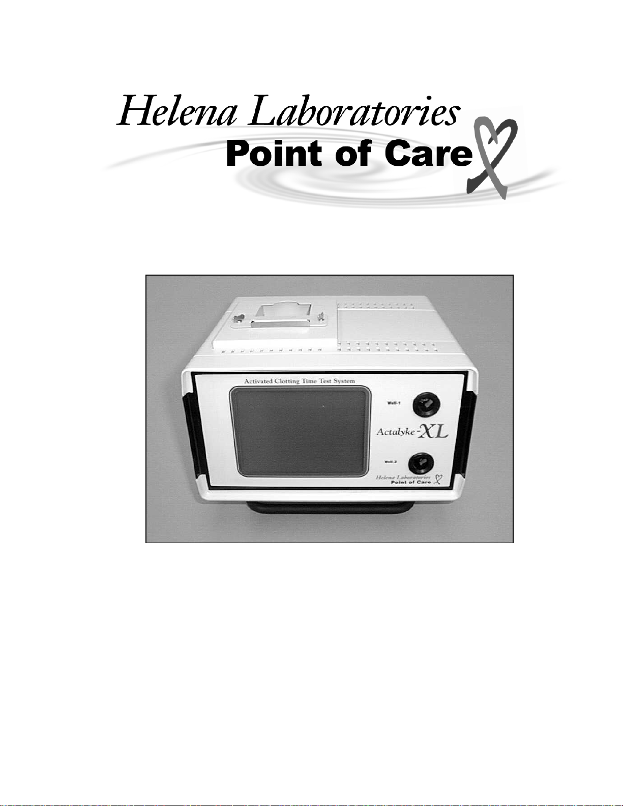
Section 1 - Instrument Use and Function
Actalyke® XL Activated Clotting Time Test
System (Figure 1-1) is used to perform the
Activated Clotting Time (ACT) test, a whole
blood coagulation assay used at the patient
site to monitor heparin therapy. The system
is portable and designed to perform a range
of whole blood coagulation tests at the
point-of-care, using Activated Clotting Time
(ACT) measurement techniques.
ACTALYKE XL is intended for in-vitro
diagnostic use only, and is for use in a
laboratory or point-of-care environment.
The ACTALYKE XL System can be used
whenever and wherever ACT testing is
desired, such as:
•Hemostasis Laboratory
•Cardiopulmonary Bypass Surgery
•Hemodialysis
•Extracorporeal Membrane Oxygenation
(ECMO)
•Percutaneous Transluminal Coronary
Angioplasty
•Cardiac Catherization
•Critical Care
The ACTALYKE XL System provides an
alternative to other Activated Clotting Time
(ACT) methodologies. The instrument
monitors moderate to high levels of heparin
during various surgical and medical proce-
dures, with good sensitivity, linearity and
precision.
The ACTALYKE XL System is a dual-
detector analyzer with a printer. The
instrument is modular in construction for
enhanced durability, portability, and flexible
storage options.
The ACTALYKE XL System has program-
mable test and output parameters.
Actalyke Test Tubes are manufactured to
the highest specification for accurate and
precise test results. Each tube contains a
clotting activator and magnet.
Refer to the procedure supplied with the
tubes for information on the following areas:
Summary
Principle
Reagents
Instruments
Specimen Collection and Handling
Procedure
Performance Characteristics
Reference Ranges
Bibliography

ACTALYKE XL ONE - Instrument Use and Function
1-2
Figure 1-1. ACTALYKE XL

ACTALYKE XL TWO - Principles of Operation
2-1
Section 2 - Principles of Operation
Operation is controlled by a microprocessor,
its program and memory, and a touch screen
liquid-crystal display (LCD) controlling
selections.
The computer runs a self-test at power On to
detect error conditions or potential problems.
Setup access can be controlled using
operator identification numbers, passwords,
and the three levels of security access.
The test wells of the instrument incorporate a
test tube identification sensor and a highly
sensitive clot detection mechanism. The test
tube identification sensor reads and enters
the test type for the ACT tube(s) in use. The
clot detection mechanism operates using a
magnet contained in a test tube and a set of
two solid-state, magnetic detectors located in
the test well.
One magnetic detector is located at 0° and
the other at 90°, with respect to the test tube.
When a test tube is inserted into a test well,
the detector at 0° senses the presence of the
magnet as the tube slowly rotates.
As a clot forms, the fibrin strands cause the
magnet in the tube to rotate. The detector at
90° senses the motion of the tube magnet
and a clotting end-point is determined. This
two-point detection sensing system mini-
mizes the possibility of a missed end-point.
The test well holds the test tube. When Start
is pressed for the test well in use, the
microcomputer turns on the motor, which
rotates the test tube. The heater remains at
a constant 37°C + 0.5, and is monitored by
the internal electronics. When the clotting
end-point is detected, the instrument notifies
the operator that the procedure is complete
by activating an audible indicator, displaying
the results and/or printing the results.

ACTALYKE XL TWO - Principles of Operation
2-2
Figure 2-1. Block Diagram
Controller
Computer
LIS Barcode
Wand
Keyboard
Floppy Drive LCD Display
Touch Screen Motor
Temperature
Sensors
0° Hall Sensors
90° Hall Sensors
Test Tube
Barcode Readers Heaters
Heater Driver
A
larm
Printer
PCB Power Supply
Power SupplyBattery
External Devices

ACTALYKE XL THREE - Precautions and Limitations
3-1
Section 3 - Precautions and Limitations
3.1. The entire Operator’s Manual should be
read and understood before attempting
instrument operation.
3.2. Refer to the procedures supplied with
the activator kits for proper testing protocols.
3.3. Provide adequate room at the sides and
back of the instrument for good air circula-
tion.
3.4. Do not expose the instrument to drafts or
to direct sunlight. Do not operate at
temperatures above 30°C (86°F), or below
15°C (59°F), or allow prolonged exposure to
high humidity.
3.5. Do not place the instrument near a
strong source of electromagnetic interfer-
ence, such as a centrifuge, X-ray machine,
etc.
3.6. WARNING: Do not use the instrument
in any area, which has, or is thought to have,
been exposed to explosive gases.
3.7. For AC outlet specification, see the
serial number plate located on the back of
the instrument.
3.8. For emergency shut down, unplug the
instrument power cord. To unplug the
instrument from the power supply always
disconnect from the AC outlet. Firmly grasp
the plug and pull. Do not remove the plug by
pulling the line cord. With the power cord
disconnected, turn the power switch Off.
3.9. No operation or maintenance should be
undertaken by the operator, which requires
the removal of the instrument's covers unless
specified in this manual.
3.10. Do not use excessive force when
making selections on the instrument display.
3.11. Do not attempt to insert any material
into the instrument other than an ACT tube,
an Electronic Clotting Tube, the temperature
probe holder supplied with the Actalyke
Thermometer, or an item this manual
indicates as appropriate.
3.12. If resistance is encountered when
inserting a tube into the test well, or there is
resistance when the tube is rotating, do not
force the test tube into the test well. Care-
fully remove the test tube and check the well.
Remove any obstruction before using the
instrument further.
3.13. All guidelines pertaining to the handling
of fresh whole human blood should be
adhered to when handling the test tubes and
operating the instrument.
3.14. Used test tubes should be considered
contaminated and may represent a biohaz-
ard. These should be handled and disposed
of in accordance with the user’s policy
regarding contaminated and biohazardous
materials.
3.15. Should instruments be contaminated by
blood or blood derivatives, clean the area
contaminated with a commercial virucidal
and germicidal agent. Observe where
specimens are used inside the instrument,
and confine cleaning to that area. Wipe up
the agent residue, as these materials may
contain alcohol, which is corrosive to metal
surfaces.
No harsh cleansers, acids, or bases should
be used or spilled on inner or outer surfaces.
Do not immerse the unit. ALWAYS TURN
THE POWER SWITCH OFF AND UNPLUG
THE MAIN POWER CORD BEFORE
CLEANING.
3.16. The instrument's systems are designed
for use only with ACT tubes. Do not use the
instrument with test tubes that are past the
expiration date marked on the tube label and
corresponding test tube box.
3.17. With a properly maintained and
operated instrument, the prime external
factor affecting the accuracy and precision of
the test is the quality of the blood specimen
used. Specimen contamination, inappropri-
ate operating technique and excessive
temperature variations will also affect the test
results.

ACTALYKE XL THREE - Precautions and Limitations
3-2
3.18. The ACT test results may be affected
by hemodilution, hypothermia, pharma-
cologic compounds and various
coagulopathies. Test results should be
interpreted with respect to the patient’s
condition and the clinical circumstances,
such as anticoagulation therapy.
Test results, which do not agree with
expected values or are inconsistent, should
be repeated. Any test result of ≥1500
seconds has no clinical value, and the test
should be repeated immediately. These
samples should be further evaluated using
other diagnostic methods, if indicated. See
section 7.3.
3.19. If further validation of the system is
required, several tests should be run using
Actalyke Quality Control Materials or other
commercial coagulation controls.
3.20. If a printout is to be part of a permanent
record, photocopy the printout and save the
photocopy.
3.21. Instructions for the "responsible body*"
(*Under IEC 61010-2-101:2002 -- the
person(s) responsible for the use and
maintenance of equipment and for ensuring
that operators are adequately trained for
eliminating and reducing hazards involved in
removal from use, transportation, or dis-
posal.)
3.22. Action(s) to be taken in case of
malfunction: See section 3.8 and 10.2.
3.23. Requirements for handling biohazards:
Due to potential biohazard risk from human
blood, guidelines pertaining to Universal
Precautions shall be adhered to when
handling the samples and operating this
instrument. This includes the use of protec-
tive gloves and any other protective
equipment as warranted for safe handling
and disposal of test tubes and use, transpor-
tation and disposal of this device. For
information on minimizing biohazard risk, see
to section 3.15.
3.24. Storage and transport environmental
requirements:
Operating Temperature range: 15° to 30° C
Storage and shipping temperatures: -20° to 45° C
3.25. The Helena Agent shall provide a
power cord or adapter of the proper configu-
ration for the country in which the instrument
is to be installed. The power cord or adapter
will comply with IEC 60227, IEC 60245, or be
certified as rated for the power specified in
section 9 of this manual.
3.26. Use standard precautions when
handling disks. Refer to the disk jackets or
inserts for appropriate precautions.
3.27. The disks should be removed when not
in use, to prevent damage.
3.28. Keep disks away from magnets
(including ACT tubes and ECT devices), as
stored information may be lost. Do not place
disks near a magnetic source or a strong
source of electromagnetic interference.
3.29. Formatting a disk, which already
contains data, will erase the original data.

ACTALYKE XL FOUR - Hazards
4-1
Section 4 - Hazards
4.1. If the instrument is used in a manner
not specified by this manual, protection
provided by equipment design may be
impaired.
4.2. This unit contains high voltages, which
can be extremely dangerous. ALWAYS
TURN OFF THE POWER, DISCONNECT
THE MAIN POWER CORD, AND USE
EXTREME CARE when attempting to clean
or repair.
4.3. When operating the instrument on AC
power, do not attempt to do so without
plugging the power cord into an easily
accessible, grounded AC wall outlet of the
proper voltage and frequency. This informa-
tion is contained on the serial number plate
located on the back of the instrument.
4.4. Running this instrument in the US on
220 V AC is prohibited. This instrument
requires a zero reference on AC input, so
cannot be run on 220V AC in the US. Fire
protection is not assured if this is not
followed.
4.5. Do not lubricate the instrument.
4.6. Use only the test tubes specified by the
Helena Laboratories procedure in use.
Damage to the instrument may result from
introducing some types of solutions into the
instrument.
4.7. Follow safe handling and disposal
procedures for test tubes used with this
device.
4.8. Keep flammable liquids and flammable
vapors away from the instrument at all times.
4.9. Particular symbols may be used to
provide information to the user. Refer to
section 11.
4.10. Use only specified printer paper.
4.11. WARNING: Do not use non-
rechargeable batteries.
4.12. WARNING: External equipment
(barcode reader, keyboard, computer) that is
connected to the instrument must have no
live parts that are accessible.

ACTALYKE XL FIVE - Installation Instructions
5-1
Section 5 - Installation Instruction
WARNING: Read section three, Precau-
tions and Limitations, and section four,
Hazards, before attempting installation or
device operation.
5.1. Unpacking and Inspection
1. Check all shipping containers for signs of
damage. If damage is found, immediately
notify the shipping carrier.
2. Carefully, unpack instrument and accesso-
ries from the shipping cartons. The packing
material should be removed undamaged, if
possible, should repacking be necessary.
3. Remove plastic wrappings from the
instrument and accessories. If scissors or a
knife is used to cut the plastic or binding
tape, take care not to scratch the instrument.
4. Inspect the instrument for any obvious
signs of damage. If damage is found, notify
the shipping carrier and Helena Laboratories.
5. Inventory all items. If any parts are
missing, recheck the packing materials
before notifying Helena Laboratories.
Table 5-1. Inventory
ACTALYKE XL Instrument
Power Cord
Operator’s Manual
Operator's Manual on CD
Roll of Actalyke Thermal Printer Paper
Actalyke XL Installation Report Form
Actalyke XL Program Disk
Table 5-2. Additional Materials
Required Materials
XL-ECT Actalyke Electronic Clotting Tube
A-PPR Actalyke Thermal Printer Paper
Available Materials
5757 Actalyke Thermometer
5758 Barcode Reader and Cable
5759 Actalyke XL Battery Pack
C-ACT Celite Tube
K-ACT Kaolin Tubes
G-ACT Glass Bead Tubes
MAX-ACT MAX-ACT Tubes
AQC-H Actalyke Whole Blood QC
(for C-ACT, K-ACT, & MAX-ACT)
AQC-L Actalyke Whole Blood QC
(for G-ACT)
5.2. Installation
This instrument is a Category II device under
EN 61010-1, for use in a laboratory or similar
environment.
1. Select an environment free of drafts, direct
sunlight, excessive humidity and dust, and
temperature fluctuations. Ambient tempera-
ture should be between 15°C to 30°C (59°F
to 86°F).
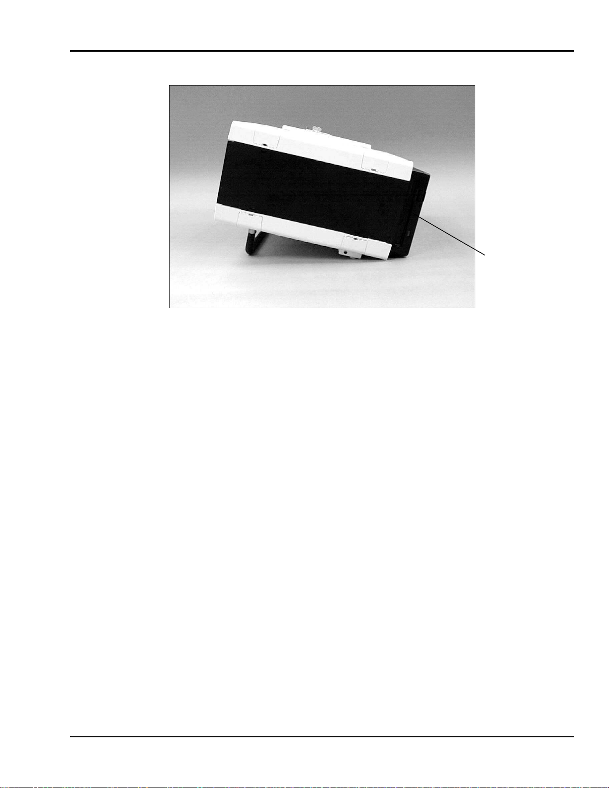
2. Place the instrument on a flat, rigid,
horizontal surface, preferably located near
the patient. Using the carrying handle/stand,
prop up the instrument (Figure 5-1).
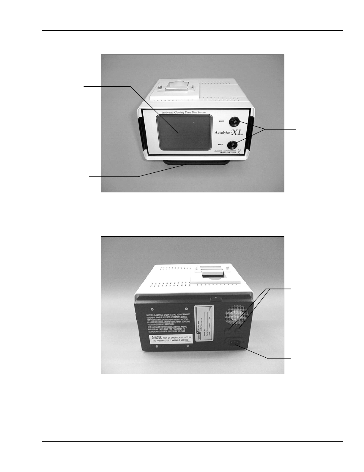
3. Confirm the instrument is Off (Figure 5-3).
The one connector, accessible from the rear
(Figure 5-2), is an IEC connector. Plug the
power cord into this connector and plug the
other end into a grounded wall outlet of the
proper voltage and frequency. Because the
power cord is the mains disconnect device,
the wall outlet used should be easily acces-
sible. These specifications can be found on
the serial number plate located on the back
of the instrument.
The wall outlet should not be on the same
circuit as any large load device such as a
refrigerator, compressor, centrifuge, etc. The
instrument circuitry contains filters to reduce
the effect of line voltage fluctuations; how-
ever, they should still be avoided.
An additional caution for US users: This
instrument requires a zero reference on AC
input, so it cannot be run on 220V AC in the
US. Fire protection is not assured if this is
not followed.
4. To connect the instrument and the optional
barcode reader or an external keyboard
and/or to connect to an external computer
(LIS): Confirm the instrument is Off (Figure
5-3). On the left side of the instrument
(Figure 5-5 or Figure 5-6), remove the

ACTALYKE XL FIVE - Installation Instructions
5-2
appropriate panel to access the desired
connection(s). Plug the device and/or LIS
into the instrument.
5. Turn the instrument On (Figure 5-3).
When the Enter Operator ID screen (Figure
6-1) displays, select OK. When the Run Test
screen (Figure 6-2) displays, confirm the
screen reads Charging: in the lower left
corner. The instrument’s battery may need
charging for up to 18 hours to be at full
capacity. See section 7.4 for more informa-
tion on the battery.
6. Load the roll of printer paper (Figure 5-3
and Figure 5-4); see section 10.1.5 for
instructions.
7. Install the F2 fuse (the fuse and fuse
holder are secured to the front of the instru-
ment during shipping). To install the fuse,
place the fuse in the fuse holder and then
place the holder in the F2 fuse position
located on the left rear of the instrument.
Using a small flathead screwdriver, push the
holder in and rotate clockwise until it is
seated.
5.3. Verification of Functionality
Read the entire Operator’s Manual. With the
instrument turned On, complete the applica-
ble section of the Actalyke XL Installation
Report as the following steps are performed:
1. Verify the Operating Environment
Temperature falls within the specified range.
Refer to section 9.1 for specifications. Make
the necessary notations on the installation
report.
2. Perform the Test Well Temperature
Check for each test well. Refer to sec-
tion 8.1.6 for instructions. Make the
necessary notations on the installation
report.
3. Perform the Clotting Time Check for
each test well. Refer to section 8.1.1 for
instructions. Make the necessary notations
on the installation report.
4. Perform a QC of Individual Coagulation
Assay for each test well. Refer to sec-
tion 8.1.2 and to the procedure supplied with
the Actalyke tubes for instructions. Make the
necessary notations on the installation
report.
Should any problems occur during installa-
tion, refer to section 10.2, or call Helena
Laboratories.
ACTALYKE XL FIVE - Installation Instructions
5-3
Figure 5-1. Actalyke XL, front view
Figure 5-2. Actalyke XL, rear view
Test Wells
Displa
y
Carrying Handle
/ Stand
IEC / Power Cord
Connection
Fuses

ACTALYKE XL FIVE - Installation Instructions
5-4
Figure 5-3. Actalyke XL, top view
Figure 5-4. Actalyke XL, top view with paper
Serrated Plate
A
djustment
Screws
A
djustment
Screws
Paper Ou
t
Paper In
Power Switch
Paper Retainer

ACTALYKE XL FIVE - Installation Instructions
5-5
The instrument’s left side will resemble either Figure 5-5 or 5-6.
Figure 5-5. Actalyke XL, left side view
Figure 5-6. Actalyke XL, left side view
Keyboard or Barcode Reader Connection
External Computer (LIS) Serial Connection
External Computer (LIS) Serial Connection
Keyboard or Barcode Reader Connection
ACTALYKE XL FIVE - Installation Instructions
5-6
Figure 5-7. Actalyke XL, right side view
3½” Floppy
Disk Drive
Table of contents


