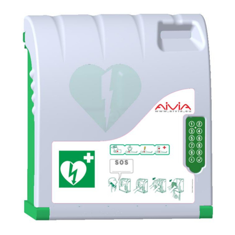
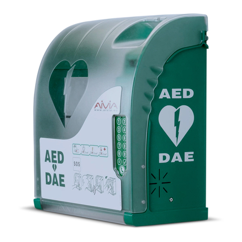
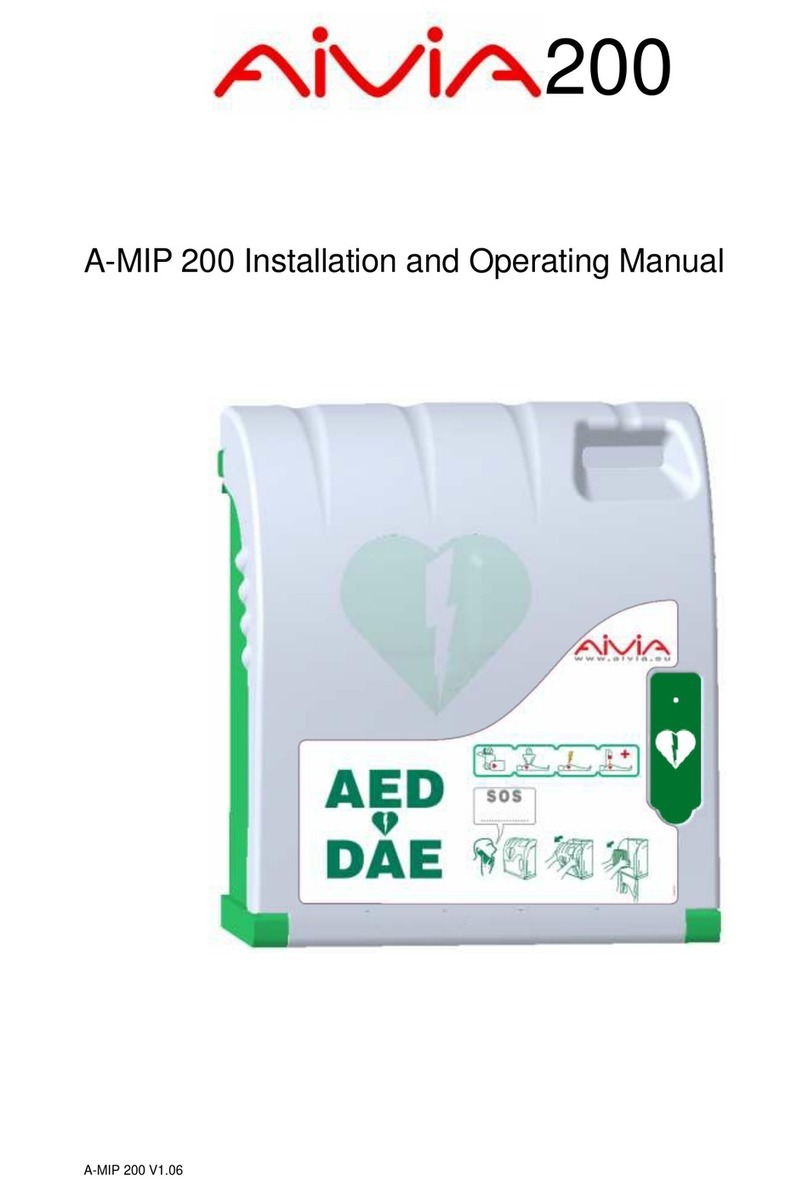
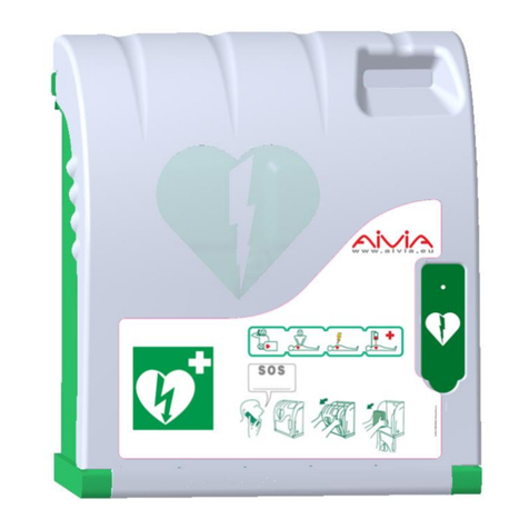
Aivia A-MIP 200 User manual

200
®
A-MIP 200 Installation and user guide
A-MIP 200 Manuel d’installation et d’utilisation
A-MIP 200 Manual de instalación y funcionamiento

2
E
N
G
L
I
S
H
General Information
Important
Read this manual before installation and use of the
AIVIA. Read this section carefully and follow the
instructions.
The warranty does not cover damage caused by
failure to follow these instructions.
The AIVIA 200 cabinets are wall mounted protection
units that serve to house and shelter AED’s.
The AIVIA 200 cabinet does not ensure control of the
AED. It is the sole responsibility of the
DISTRIBUTOR to inform their own SUB-
DISTRIBUTORS and END USERS of their obligation
to verify the presence and operating status of the
AED by carrying out regular on-site checkups. The
AIVIA 200 cabinet triggers a visual and audible
alarm. The alarm is intended as a warning signal, but
no data log is recorded. It is not possible to remotely
control the presence and operating status of AED’s
in the AIVIA 200 cabinet. The AIVIA 200 cabinet
should in no case be a substitute for the checks and
inspections recommended by the manufacturer of
the defibrillator.
Installation must be carried out by a qualified
operator or authorized by the AIVIA’s manufacturer.
Never install an AIVIA in direct exposure to sunlight.
The AIVIA 200 without the heater option must be
installed in a temperate environment, in accordance
with the manufacturer’s specifications of the
defibrillator and operating temperatures of the AIVIA.
The characteristics of the AIVIA are subject to
changes without notice.
The manufacturer of the AIVIA reserves the right to
change products at any time, including unlimited
modifications to previously delivered products.
AIVIA® is a registered trade-mark of PYRESCOM,
used under license.
Patent Pending.
Safety
• To avoid risk of fire or electric shock, the AIVIA
should not be exposed to any naked flame.
• Leave a space of at least 5” (13 cm) around the
AIVIA to assure proper ventilation.
• Keep the AIVIA away from radiators or any other
heat sources. Do not place the AIVIA near any
devices that generate heat. Do not place anything
under the AIVIA.
• To avoid damage, do not insert objects into any of
the openings in the AIVIA.
• Never install the AIVIA in direct exposure to
sunlight.
• Do not expose the AIVIA to any moisture when the
door is open.
Warranty
Limited Warranty, warranty is void:
• For defects that are the result of materials and
products supplied by Reseller or end user.
• For defects that are the result of assembly or
installation made by Reseller or end user ; Do not
insert any objects into any openings; Do not
disassemble the various elements that make up the
AIVIA; Only qualified personnel may carry out repairs
on the AIVIA.
• For defects resulting wholly or partially from normal
wear and tear of consumables (accumulator,
batteries, etc.), from damages or accidents
attributable to Reseller or end user.
• In case of any modifications or abnormal uses that
do not conform with the product's purpose or usual
functions; and if the product is used in such a way
that goes against the advice or recommendations
provided by Supplier; Any operation or assembly
procedures expressly prohibited or not
recommended by this manual are forbidden.
• In case of negligence, insufficient supervision or
maintenance on the part of the Reseller or end user.
• In case of force majeure.
Environmental information
• When returning the AIVIA, you should only use the
original packaging.
• Dispose of the AIVIA properly in accordance with
all state, province and country regulations.
Maintenance
CAUTION
ONLY AN AUTHORIZED OPERATOR CAN
CARRY OUT MAINTENANCE OPERATIONS.
• The mounting screws and anchor type must be
suitable for the type of surface on which the AIVIA is
to be mounted to.
• The manufacturer cannot be held liable for improp-
er installation or in the case of an accident or injury
during its installation.

3
Contents
Installation
Important 4
AIVIA components 4
Identification label 4
Initial opening 4
AIVIA installation 5
Connect power to the AIVIA 6
Setting up the defibrillator 7
Placing the seals 7
Pictograms 7
Use
Low light operation 8
Heating operation 8
Audible and Visual Alarm Options 8
Temperature Alert 8
Using the AIVIA 8
After using the defibrillator 8
AIVIA maintenance 8
Troubleshooting 9
Specifications
Mechanical properties 11
Technical properties 11
Compliance 11
Electrical Installation 10
E
N
G
L
I
S
H

4
Installation
Important
Read this manual with caution before setting up and
using the AIVIA.
Never install an AIVIA in direct exposure to
sunlight. You risk exposing the defibrillator to
excessive temperatures.
AIVIA components
1
2
4
3
6
5
7
1. Electronic compartment.
2. Light sensor.
3. Seal support.
4. Heating element.
5. Low light and alarm alert indicator lights.
6. Door.
7. Identification label.
Identification label
• The identification label is located inside the AIVIA.
• In the event you need to contact customer service
or your distributor, please make sure you have your
AIVIA reference and serial number available.
Serial Number
Reference
Initial opening
• To open the AIVIA door before hanging it to a wall,
use a small screwdriver.
• Slide the screwdriver between the door and the
AIVIA frame (See illustration below).
• Pull the screwdriver upwards, being careful not to
damage the AIVIA.
• Repeat the above steps on the other side of the
AIVIA.
E
N
G
L
I
S
H
8
8. Mounting holes.
9. AED bungee cord.
9

5
Useful area for AIVIA working space
Installation
AIVIA Installation
Never install the AIVIA in direct exposure to sunlight.
The AIVIA must be installed in a protected environment,
conforming with the instructions of the defibrillator
manufacturer.
• Installation must be carried out by a qualified
operator.
• If the AIVIA is installed in a public street or place
with public access, install a ground support structure
(abutment) or column. Please remember that it must
comply with the regulation in force regarding
accessibility standards in each country, state and / or
area.
• The ADA (Americans with Disabilities Act)
guidelines specify that in an un-obstructed approach,
the reach to the door handle shall not exceed
48” (122 cm) from the floor. The maximum side
reach is to be less than 54“ (137 cm).
• The mounting screws and anchor type must be
suitable for the type of surface on which the AIVIA is
mounted to.
• Allow for a free working area when installing the
AIVIA as specified in the diagrams below.
• The exact dimensions of the AIVIA are provided at
the end of this document in the section
“Specifications”.
Useful area for AIVIA working space
8 7/16"
(215 mm)
7 1/2"
(190 mm)
8 11/16"
(220 mm)
5 15/16"
(150 mm)
8 11/16"
(220 mm)
5/16"
(8.5 mm)
• Leave a clear space of 55 1/8" (140 cm) in front of
the wall where the AIVIA is installed to allow its door
to open easily.
• To mark mounting holes and cable openings on the
wall, use the drilling template provided with
packaging.
• Put the template against the wall, with the arrow
facing upwards and the letter “L” at your left.
55 1/8" (1400 mm)
Mounting holes
24VDC Cable
openings
E
N
G
L
I
S
H
L: Left

6
Installation
Use a suitable mounting method (screw and anchor type) for the type of surface on which the AIVIA is
to be mounted to.
• The mounting system must be able to support a
minimum load of 44 lb (20 kg).
• Mounting example:
• The screw head and washer together must not
exceed 5/16" (8 mm) thickness.
• Prior to mounting on the wall, pass the 24v wiring
from the wall through the square hole in the back of
the cabinet.
Affix the AIVIA using the 3 mounting holes.
12
3
4
1. Wall surface
2. Screw anchor
3. Mounting screw, M6 minimum, M8 maximum
4. Flat washer 9/16" (14 mm) maximum
Connect power to the AIVIA
• The AIVIA must be supplied with 24VDC power,
ensure compliance with the "Electrical
Installation" section.
• Remove the screw using a cross-head screwdriver.
• Open the access panel from the top, being careful
not to pull on the power supply wire.
1
2
1. Access panel screw
2. Electronics access panel
• Run power wiring through the cable entry.
• Connect the cable to the supply terminal,
respecting proper polarity.
• Connect the terminal to the power connector.
• Ensure that the AIVIA is powered up by checking
that the red warning lights are flashing.
• To close the access door, insert the bottom of
access door first.
• Screw the access door back using a Philips
screwdriver.
2
1
1. Cable entry
2. Power supply cable
2
1
1. +24V DC Red cable
2. 0V Black cable
1
1. Power connector.
E
N
G
L
I
S
H

7
Installation
Setting up the defibrillator
• Place defibrillator behind bungee cord and slide the
defibrillator all the way to the bottom of cabinet.
TWO OPTIONS
FOR ALARM ACTIVATION
Option #1: Alarm is actived upon opening the
cabinet door.
When the door is closed - alarm is armed. When the
door is opened the alarm is activated.
Option #2: Alarm is activated when the
defibrillator is removed.
• Insert the cable through the defibrillator handle.
• To arm the alarm:
Press the lock button (1)
Insert the cable into the hole (2)
When accessing AED, open cabinet door and when
defibrillator is removed alarm is activated by
disengaging cable.
• The surfaces must be clean, dry and free of any
grease.
• Remove the protective film from the seal.
• Stick the seal covering both the AIVIA door and
chassis.
• Seals must be placed on both sides of the AIVIA.
Pictograms
• The sequence printed on the AIVIA door
indicates the procedure to follow in case of
emergency. Never cover these operating
instructions.
• If the emergency call number is not written under
“S.O.S.” or “Emergency” (eg. 911 for US and
Canada, 112 for EU…) make sure to write the
number to call under “S.O.S.” or “Emergency”.
E
N
G
L
I
S
H
or S.O.S.
2
1
1. Slide in AED vertically.
2. Bungee cord to hold AED securely in
place.
1
2
Placing the seals
• The AIVIA is shipped with two sets of security
seals.
• The seals give evidence of the door opening.
• Regularly inspect the seals condition.
Seal placement
• Completely close the AIVIA door, making sure to
pull the bottom of the door towards you before
shutting the door.

8
Use
Low light operation
• The AIVIA is equipped with a light luminosity
sensor. In low ambient light conditions, flashing
white lights help identify the location of the AIVIA.
Heating operation
• The heating system allows to maintain the AED
operating temperature within certain limits. In
extreme cold temperatures, it is important to check
that the temperature alert is not signaled by the
flashing red lights.
• The fan allows the heat to be extracted from the
AIVIA. In hot weather, it is important to check that
the temperature alert is not signaled by the flashing
red lights.
Audible and Visual Alarm Options
OPTION #1:
• When you open the door, flashing red lights give a
visual warning.
• An audible alarm, will sound for about 3 minutes.
• Close the door to stop the alarm.
OPTION #2:
• When the cable is disengaged upon removal of the
AED, flashing red lights give a visual warning.
• An audible alarm will sound for about 3 minutes.
• Insert the cable into the hole on inside of cabinet
simultaneously holding down lock button on front of
cabinet to stop the alarm. See the instructions in the
section "Setting up the defibrillator".
Using the AIVIA
If you are a witness of an incident requiring the
use of a defibrillator:
• Call emergency services.
Speak in a strong, clear voice, describe the
situation and specify the location of the incident.
• Open the AIVIA door by pulling the cover
outward.
• Take the defibrillator out.
• Go to the victim.
• Activate the defibrillator.
• Follow the defibrillator instructions.
After using the defibrillator
• Do not place the defibrillator back inside the AIVIA
before reactivating it.
• Follow the instructions in the defibrillator manual to
reset it for use.
• The manufacturer may be able to help reactivate
the defibrillator. Please feel free to contact them.
• After reactivating the defibrillator, replace it inside
the AIVIA using the instructions in the section
"Setting up the defibrillator".
• Replace the seal using the instructions in the
section "Placing the seals".
AIVIA Maintenance
• Clean the surfaces of the AIVIA using a soft damp
cloth. Wipe the AIVIA with a soft, clean and dry cloth.
Do not use chemical products or cleaners, which may
damage the AIVIA.
• Do not rub the AIVIA with a hard object, which may
scratch or permanently damage the surfaces.
• Do not use any high pressure cleaner.
• Regularly inspect the condition of the seals.
• If the AIVIA seals have been broken, make sure
that all items of the defibrillator are present and
working properly.
In case of any doubt, contact your defibrillator
distributor.
Temperature alert
• The temperature alert, indicated by a continuously
flashing red light when the door is closed, is
triggered when temperatures fall below 41°F (5°C)
or rise above 104°F (40°C).
E
N
G
L
I
S
H
or S.O.S.

9
Troubleshooting
•Red lights do not flash when power is applied.
1. Check wiring polarity.
2. Check power supply connection.
3. Check voltage (24VDC) at the terminals.
4. Check proper insertion into terminals.
5. Contact distributor.
•White lights do not flash or flash weakly in low ambient light.
1. Check the AIVIA power supply.
2. Contact distributor.
•Red lights do not flash when the cable is taken off.
1. Check the AIVIA power supply.
2. Contact distributor.
•Siren does not sound when the cable is taken off.
1. Verify that the 1st box for “Sirène/Alarm” is checked on the AIVIA label
identification (see example page 4).
2. Check the AIVIA power supply.
3. Contact distributor.
E
N
G
L
I
S
H

10
Electrical Installation
Power Supply Unit
Must be located outside the AIVIA, never
installed inside the AIVIA.
•The power supply block must include:
- A 10A/30mA residual current device, serving
both to protect and disconnect the hardware.
- Safety Extra Low Voltage Wiring* or equivalent
24VDC +-2% / 3A Class II, and IEC 60950-1
conform.
- The cable connecting the residual current device
and the power supply must be a section of 15AWG
(1,5 mm²).
•The main connection must include the primary
phase, and neutral.
•The maximum full load secondary voltage drop
must not exceed 2%, or 23.5V at the AIVIA terminal.
•The power block must be dust and waterproof, and
ventilated**.
• Wires must be held against themselves by a
collar at the nearest of the holding terminals. The
power block wiring must conform to standards in
force in the country of use.
* Recommended power supply: Meanwell HDR100-
24 or DR100-24
** Natural or forced convection depending on the
environment and thermal characteristics at maximum
load.
Safety Extra Low Voltage Wiring
(SELV)
• Type U1000R2V. 2 insulated jacketed conductors,
15AWG (1.5 mm²) area, 33 feet (10 m) maximum
length.
• Use red or maroon color cable for the +24V line.
• Use black or gray color cable for the 0V line.
E
N
G
L
I
S
H

11
Specifications
Mechanical properties
• Weight
- U2A200-XX101: 7.05 lb (3.2 kg)
•Materials:
- Door: Polycarbonate
- Frame: ABS
- Bracket: ABS
- Hatch: ABS
15 1/4"
(388 mm)
7 15/16"
(201 mm)
16 5/8" (423 mm)
Technical properties
• Power supply:
- SELV 24VDC +-2% / 3A IEC 60950-1 conform.
• Electrical consumption:
- U2A200-XX101:
Minimum: 0.9 mA
Maximum: 2400 mA
Sound level: 103 dB / 39 in (1m)
• Operating temperatures and humidity:
- Minimum: -4°F (-20°C) without wind-chill.
- Maximum: 131°F (55°C)
- Relative humidity: 95% without condensation
• Temperature alarms:
- Low temperature alert: 41°F (5°C)
- High temperature alert: 104°F (40°C)
• Heating:
- Heating set point: 55°F (13°C)
- Ventilation set point: 81°F (27°C)
• Maximum weight capacity: 11lb (5kg)
• Maximum altitude: 6,562 ft (2,000m)
Compliance
IEC 60950-1:2005+A1+A2
EN 60950-1:2006 (Second Edition) +A11:2009
+A1:2010 +A12:2011
UL60950-1:2007 R10.14
CAN/CSA-C22.2 N°60950-1-07+A1+A2
EN 61000-6-2:2005+A1:2006
EN 61000-6-3:2007+A1:2011
FCC Part 15:2009
ICES 003:2004
E
N
G
L
I
S
H

12
Informations Générales
Important
Lisez ce manuel avant l’installation et l’utilisation de
l’AIVIA. Lisez cette section attentivement et suivez
les instructions.
La garantie ne s'applique pas aux dommages
causés par le non respect des instructions.
Les AIVIA 200 sont des coffrets muraux de
protection qui servent à héberger et abriter les DAE.
L’AIVIA 200 n’assurant pas le contrôle du DAE, le
DISTRIBUTEUR devra vérifier sous sa seule
responsabilité, et informer ses propres SOUS-
DISTRIBUTEURS et UTILISATEURS qu’ils leur
incombent de vérifier l’état de fonctionnement du
DAE et sa présence en assurant des contrôles
physiques réguliers sur site. Les AIVIA 200
déclenchent des alarmes locales visuelles et
sonores. L’alarme est une information ponctuelle
active uniquement pendant l’anomalie, aucun
historique des anomalies n’est enregistré. En aucun
cas l’état de fonctionnement et la présence des DAE
hébergés dans les AIVIA 200 n’est vérifiable à
distance. L’AIVIA ne peut en aucun cas se substituer
aux contrôles et vérifications préconisés par le
fabricant du défibrillateur.
L’installation doit être réalisée par un opérateur
qualifié ou habilité par le fabricant de l’AIVIA.
Ne jamais installer l’AIVIA exposé directement au
soleil.
L’AIVIA 200 sans chauffage doit être installé dans un
environnement tempéré, conformément aux
prescriptions du fabriquant du défibrillateur et
températures de fonctionnement de l’AIVIA
Les caractéristiques de l’AIVIA sont susceptibles
d'être modifiées sans avis préalable.
Le fabricant de l’AIVIA se réserve le droit de modifier
les produits à tout moment, sans contrainte de
modification des produits précédemment livrés.
La marque commerciale AIVIA® est une marque
déposée de PYRESCOM, utilisée sous licence.
Brevet déposé.
Sécurité
• Pour éviter tout risque d'incendie ou de choc
électrique, aucune flamme nue ne doit être placée à
proximité de l’AIVIA.
• Laissez un espace d'au moins 5” (13 cm) tout
autour de l’AIVIA pour assurer une bonne ventilation.
• Éloignez l’AIVIA des radiateurs ou de toute autre
source de chaleur. Veillez à ne pas placer l’AIVIA au
dessus d'autres appareils qui pourraient chauffer.
Veillez à ne rien placer sous l’AIVIA.
• Pour éviter tout dommage, n'insérez pas d'objets
dans les orifices.
• Ne jamais installer l’AIVIA exposé directement au
soleil.
Garantie
Garantie Limitée, la garantie est nulle en cas de:
• Défauts liés à des matériaux ou produits fournis par
le distributeur ou l’utilisateur.
• Défauts liés à l’assemblage ou l’installation réalisée
par le distributeur ou utilisateur. Ne démontez pas
les éléments constituant l’AIVIA. N'insérez pas
d'objets dans les orifices. Seul le personnel habilité
est autorisé à effectuer des réparations sur l’AIVIA.
• Défauts partiellement ou entièrement liés à l’usure
normale des consommables (accumulateur , piles,
etc.) ou liés à des dommages ou accidents
attribuables au distributeur ou à l’utilisateur.
• Modifications ou utilisations anormales qui sont non
conformes à la finalité ou fonctions habituelles du
produit; ou encore si le produit est utilisé d’une
façon allant à l’encontre des conseils et
recommandations du fournisseur. Toutes opérations
ou procédures d’assemblage expressément
défendues ou non recommandées dans ce manuel
sont interdites.
• Négligence, contrôle ou maintenance insuffisant de
la part du distributeur ou utilisateur.
• Force Majeure.
Informations concernant
l’environnement
• En cas de retour de l’AIVIA, vous devrez utiliser
l’emballage d’origine complet.
• Jetez l’AIVIA conformément aux régulations des
différents Pays, Etats, Provinces et Comtés.
Maintenance
ATTENTION
SEUL UN OPERATEUR HABILITÉ EST AUTORISÉ
A REALISER DES OPERATIONS DE
MAINTENANCE.
F
R
A
N
Ç
A
I
S
• N'exposez pas l’AIVIA à l'eau lorsque la porte est
ouverte.
• La fixation doit être adaptée au type du support sur
lequel l’AIVIA est fixé.
• Le fabriquant ne pourra être tenu responsable en
cas de fixation inadéquate ou en cas d'accident ou
de blessures lors de la fixation.

13
Sommaire
Installation
Important 14
Présentation de l’AIVIA 14
Etiquette d’identification 14
Première ouverture 14
Fixation de l’AIVIA 15
Branchement de l’alimentation à l’AIVIA 16
Mise en place du défibrillateur 17
Installation des scellés 17
Pictogrammes 17
Utilisation
Fonctionnement du mode nocturne 18
Fonctionnement de l’option chauffage 18
Options Alarme Visuelle et Sonore 18
Alerte de température 18
Utilisation de l’AIVIA 18
Après l’utilisation du défibrillateur 18
Entretien de l’AIVIA 18
Dépannage 19
Spécifications
Caractéristiques mécaniques 21
Caractéristiques techniques 21
Conformités 21
Installation électrique 20
F
R
A
N
Ç
A
I
S

14
Installation
Important
Lisez attentivement la totalité de ce mode d'emploi
avant l’installation et l’utilisation de l’AIVIA.
Ne jamais installer l’AIVIA exposé directement au
soleil. Vous risquez d'exposer le défibrillateur à
des températures excessives.
Présentation de l’AIVIA
1
2
4
3
6
57
1. Compartiment Electronique
2. Capteur de lumière
3. Position des scellés
4. Film chauffage
5. Eclairages nocturne et d’alerte
6. Porte
7. Etiquette d’identification
Etiquette d’identification
• L’étiquette d’identification est collée à l’intérieur de
l’AIVIA.
• Pour toute correspondance avec le Service Client
ou votre partenaire, munissez vous de la référence
de l’AIVIA, ainsi que de son numéro de série.
Numéro de Série
Référence
Première ouverture
• Pour ouvrir la porte de l’AIVIA avant qu’il ne soit
installé au mur, munissez vous d’un tournevis fin.
• Glissez le tournevis entre la porte et le châssis de
l’AIVIA.
• Relevez le tournevis en prenant soin de ne pas
marquer les éléments.
• Réalisez cette opération des deux cotés de l’AIVIA.
F
R
A
N
Ç
A
I
S
8
8. Trous de fixation
9. Sangle de maintien.
9

15
Installation
Fixation de l’AIVIA
Ne jamais installer l’AIVIA exposé directement au
soleil. L’AIVIA doit être installé dans un
environnement tempéré, conformément aux
prescriptions du fabricant du défibrillateur.
• L’installation doit être réalisée par un opérateur
qualifié.
• Si l’AIVIA est installé sur la voie publique ou une
zone de passage, prévoir une surface au sol (butée)
ou une colonne, afin de respecter la régulation en
vigueur concernant les normes d’accessibilités dans
chaque pays, Etat ou région.
• Prendre en compte la réglementation ou les
recommandations en vigueur concernant les normes
d'accessibilités. Nous recommandons que les
poignées d'ouverture de porte soient à une hauteur
comprise entre 48" et 54" (122 cm et 137 cm).
• La fixation doit être adaptée au type du support sur
lequel l’AIVIA est fixé.
• Laissez dégagée la zone utile de l’implantation de
l’AIVIA comme spécifié dans les schémas ci
dessous.
• Les dimensions exactes de l’AIVIA sont fournies à
la fin de ce document dans la section
«Spécifications».
Zone utile pour l’implantation de l’AIVIA
8 7/16"
(215 mm)
7 1/2"
(190 mm)
8 11/16"
(220 mm)
5 15/16"
(150 mm)
8 11/16"
(220 mm)
5/16"
(8.5 mm)
• Laissez un espace dégagé de 55 1/8" (140 cm)
depuis le support mural de l’AIVIA afin de pouvoir
ouvrir facilement la porte.
• Pour marquer les trous de fixation et d’arrivée du
câble d’alimentation sur le mur, utilisez le gabarit de
perçage fourni avec l’emballage.
• Placez le gabarit de perçage contre le mur, la
flèche face à vous et la lettre « L» à votre gauche.
55 1/8" (1400 mm)
Zone utile pour l’implantation de l’AIVIA
Trous de fixation
Arrivée du câble
d’alimentation 24VDC
F
R
A
N
Ç
A
I
S
L: Left
(gauche)

16
Installation
Utilisez un ensemble de fixation adapté au type de support sur lequel l’AIVIA est installé.
• Passez les câbles d’alimentation dans le passage
de câble.
• Connectez les câbles sur le bornier d’alimentation
en respectant les polarités.
• Branchez le bornier sur le connecteur
d’alimentation.
• Contrôlez la mise sous tension de l’AIVIA en
vérifiant que les voyants d’alerte rouges clignotent.
• Remettez en place la trappe en insérant la partie
basse.
• Vissez la vis de fixation de la trappe avec un
tournevis cruciforme.
• La fixation doit pouvoir supporter une charge
minimale de 44 lb (20 Kg).
• Exemple de fixation:
• L’ensemble rondelle tête de vis ne doit pas
dépasser 5/16" (8 mm) d’épaisseur.
Fixer l’AIVIA par les 3 trous de fixation.
Branchement de l’alimentation à
l’AIVIA
• L’AIVIA doit être alimenté en 24VDC, veuillez vous
conformer a la section «Installation Electrique».
• Dévissez la vis de fixation de la trappe avec un
tournevis cruciforme.
• Basculez la trappe par le haut en prenant soin de
ne pas tirer sur le câble d’alimentation.
12
3
4
1. Support
2. Cheville
3. Vis de fixation, M6 minimum, M8 maximum
4. Rondelle plate 9/16" (14 mm) maximum
1
2
1. Vis de fixation de la trappe
2. Trappe d’accès à l’électronique
2
1
1. Passage de câbles
2. Câbles d’alimentation
2
1
1. +24VDC Câble Rouge
2. 0V Câble Noir
1. Connecteur d’alimentation
1
F
R
A
N
Ç
A
I
S

17
Installation
Mise en place du défibrillateur
• Tirer la sangle de maintien vers vous et glisser le
défibrillateur derrière.
DEUX OPTIONS
POUR ARMER L’ALARME
Option #1: Alarme sur ouverture de porte.
• Fermer la porte. L’alarme est armée et quand vous
ouvrez la porte l’alarme s’active.
Option #2: Alarme sur retrait du défibrillateur.
• Insérez le câble dans la poignée du défibrillateur.
• Armez l’alarme.
Appuyer sur le bouton de blocage (1)
Insérer le câble dans le trou (2)
• Les surfaces de collage doivent être propres,
sèches et exemptes de graisse.
• Retirez le film de protection du scellé.
• Collez le scellé à cheval sur la porte et le châssis
de l’AIVIA.
• Placez les scellés des deux cotés de l’AIVIA.
Pictogrammes
• La signalétique présente sur la porte de l’AIVIA
vous indique la démarche à suivre en cas d’urgence.
Ne recouvrez jamais ces instructions d’utilisation.
• En cas d’urgence appelez le numéro inscrit en
dessous de « S.O.S. » ou « Emergency » (ex. 911
pour les Etats-Unis et Canada, 112 pour l’UE…).
Assurez-vous d’inscrire ce numéro en dessous de
«S.O.S. » ou « Emergency ».
F
R
A
N
Ç
A
I
S
ou S.O.S.
2
1
1. Glisser le débrillateur vercalement.
2. Sangle de mainen du débrillateur.
Installation des scellés
• L’AIVIA est livré avec deux jeux de scellés.
• Les scellés témoignent de l’ouverture de la porte.
• Contrôlez régulièrement l’état des scellés.
Mise en place des scellés
• Refermez complètement la porte de l’AIVIA.
Prenez soin d’avoir tiré le pied de porte vers vous
avant de pivoter la porte.
1
2

18
Utilisation
Fonctionnement du mode nocturne
• L’AIVIA est équipé d’un détecteur de luminosité.
Quand la luminosité devient insuffisante, les voyants
blanc clignotent afin de signaler l’emplacement de
l’AIVIA.
Fonctionnement de l’option
chauffage
• Le chauffage permet de maintenir la température
de fonctionnement du défibrillateur dans certaines
limites. Par grand froid il convient de s’assurer que
l’alerte de température n’est pas signalée par le
clignotement des voyants rouges.
• La ventilation permet d’évacuer l’air chaud contenu
dans l’AIVIA. Par temps chaud il convient de
s’assurer que l’alerte de température n’est pas
signalée par le clignotement des voyants rouges.
Utilisation de l’AIVIA
Si vous êtes témoin d’un incident nécessitant un
défibrillateur:
• Contactez les secours.
Parlez d’une voix forte et claire, décrivez la situation
sans oublier de préciser le lieu de l’incident
Options Alarme Visuelle et Sonore
Option #1:
• Quand la porte est ouverte, les voyants rouges
clignotent pour donner l’alerte visuel.
• Une alarme sonnera pendant 3mn.
• Fermer la porte pour arrêter l’alarme.
Option #2:
• Quand le câble est retiré, les voyants rouges
clignotent pour donner l’alerte visuelle.
• Une alarme sonnera pendant 3 minutes.
• Insérer le câble dans le bouton de verrouillage pour
arrêter l’alarme. Voir les instructions en section
«Mise en place du défibrillateur ».
Alerte de température
• L’alarme de température, signalée par un
clignotement continu des voyants rouges porte
fermée se déclenche en dessous de 41°F (5°C) ou
au dessus de 104°F (40°C).
• Ouvrez la porte de l’AIVIA en tirant dessus.
• Saisissez le défibrillateur.
• Rendez-vous auprès de la victime.
• Mettez en fonction le défibrillateur.
• Suivez les instructions du défibrillateur.
Entretien de l'AIVIA
• Nettoyez les surfaces de l’AIVIA à l'aide d'un
chiffon doux et humide. Essuyez l’AIVIA avec un
chiffon doux propre et sec. N'utilisez pas de produits
chimiques ou de nettoyage, cela pourrait
endommager l'AIVIA.
• Ne frottez pas l'AIVIA avec un objet dur, vous
risqueriez de rayer ou d'abîmer de façon permanente
les surfaces.
• N’utilisez pas de nettoyeur haute pression.
• Contrôlez régulièrement l’état des scellés.
• Si les scellés de l’AIVIA ont étés forcés, assurez
vous de la présence de tous les éléments du
défibrillateur ainsi que de leur bon fonctionnement.
Si vous avez un doute, contactez votre revendeur de
défibrillateur.
Après l’utilisation du défibrillateur
• Ne remettez pas le défibrillateur dans l’AIVIA sans
l’avoir remis en fonction.
• Suivez les instructions du manuel du défibrillateur
pour le remettre en service.
• Votre partenaire peut vous aider à remettre en
service le défibrillateur. N’hésitez pas à le contacter.
• Après remise en service du défibrillateur, installez
le dans l’AIVIA en suivant les instructions de la
section « Mise en place du défibrillateur ».
• Installez les scellés en suivant les instructions de la
section « Installation des scellés ».
F
R
A
N
Ç
A
I
S
or S.O.S.

19
Dépannage
• A la mise sous tension les voyants rouges ne clignotent pas.
1. Vérifiez la polarité du câblage.
2. Vérifiez la connexion du câble d’alimentation.
3. Vérifiez la tension (24VDC) au niveau du bornier.
4. Vérifiez la bonne insertion du bornier.
5. Contactez votre partenaire.
• Les voyants blancs ne clignotent plus en fonctionnement nocturne.
1. Vérifiez la mise sous tension de l’AIVIA.
2. Contactez votre partenaire.
• Les voyants rouges ne clignotent pas quand je retire le câble.
1. Vérifiez la mise sous tension de l’AIVIA.
2. Contactez votre partenaire.
• La sirène ne s’active pas quand je retire le câble.
1. Vérifiez l’option Sirène soit cochée sur l’étiquette d’identification (voir page
14).
2. Vérifiez la mise sous tension de l’AIVIA.
3. Contactez votre partenaire.
F
R
A
N
Ç
A
I
S

20
Bloc Alimentation
Il doit être externe à l’AIVIA, ne jamais le
disposer à l’intérieur de l'AIVIA.
• Le bloc d'alimentation doit être constitué de:
- Un disjoncteur différentiel 10A/30mA, organe
de protection et de sectionnement du matériel.
- Une alimentation* TBTS ou équivalent 24VDC
+-2% / 3A Class II et conforme aux exigences
de la norme IEC 60950-1.
- Les câbles reliant le disjoncteur différentiel et
l’alimentation doivent être d’une section de
15AWG (1,5mm²).
• Son branchement primaire doit comporter la phase
et le neutre.
• La chute maximale de la tension du secondaire à
pleine charge ne doit pas excéder 2%, soit 23,5V au
bornier de l'AIVIA.
• Le contenu du bloc d'alimentation doit être protégé
de la poussière et de l'eau, et être ventilé**.
• Les câbles doivent être maintenus entre eux
par un collier au plus près des bornes de
serrage. Le câblage du bloc d'alimentation doit
être conforme aux normes en vigueur dans le
pays d'installation.
* Alimentation préconisée: Meanwell HDR100-24 or
DR100-24
** Convection naturelle ou forcée en fonction de son
environnement et des caractéristiques thermiques
au maximum de fonctionnement
Câble TBT
• Type U1000R2V. 2 conducteurs isolés gainés,
section de 15AWG (1,5mm²), longueur de 10
mètres maximum.
• Utilisez pour le +24V le câble de couleur rouge ou
marron.
• Utilisez pour le 0V le câble noir ou gris.
F
R
A
N
Ç
A
I
S
Installation Electrique
Other manuals for A-MIP 200
1
Table of contents
Languages:
Other Aivia Medical Equipment manuals
Popular Medical Equipment manuals by other brands

Seaward
Seaward Rigel 62353+ Practical guide

Ossur
Ossur PROPRIO FOOT Instructions for use

Fabtech
Fabtech Crossover Extensible Knee owner's manual

Helena Laboratories
Helena Laboratories Actalyke XL Operator's manual

DQE
DQE SLYDE EVACUATION SLED Series Operation manual

John Bunn
John Bunn JB02017 Operator's manual