Figure 1
Exposure
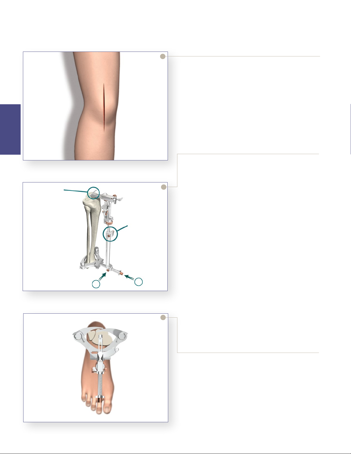
>A standard anterior midline incision can be utilized.
Any previous incision can be used or incorporated
to decrease risk of skin slough.
>e capsule can be entered through a modied mid-
vastus approach, which makes a skin incision medial
to the patella from just above the tibial tubercle to
just above the patella.
>Use a so tissue approach that allows adequate
patella visualization and sucient knee exion.
6
Tibial
Preparation
Triathlon®Knee System
Single-Use Instruments Surgical Protocol
Figure 3
is surgical technique describes cutting the tibia rst,
followed by the femur and then patella. e sequence
may be varied based upon surgeon preference.
In some patients it may be dicult to cut the femur rst
and get proper rotation due to the tibia being in the way
of the placement of the femoral sizer. In these cases it
may be benecial to cut the distal femur, then tibia, and
then go back to size and nish the femoral cuts.
Tibial Preparation
>e tibia is prepared using the Triathlon
extramedullary alignment system. Retractors may be
placed medially, laterally, and posteriorly to expose
the tibial plateau for preparation. It is important to
remove all osteophytes, menisci and remaining so
tissues. Menisci can be removed before or aer the
bone cut. If the PCL has been retained, an optional
retractor is available to cradle the PCL for increased
exposure. e knee is exed anywhere from 45
degrees to more than 90 degrees of exion depending
on surgeon preference. e tibia may be subluxed or
dislocated as required.
>e tibial plateau referencing arm of the proximal
rod is placed on the proximal tibia just anterior to
the ACL insertion. A rongeur may remove any
osteophytes that prevent satisfactory positioning.
Rotational Alignment
>e assembly must be in the proper rotational
alignment. e most common landmark referenced
is the tibial tubercle. e assembly should be
aligned with the medial third of the tibial tubercle.
>Once the rotational alignment is determined, a
headless pin is placed through the posterior xation
hole in the proximal assembly to lock it in place.
Either the anterior or posterior xation holes may
be used to set the exion extension and rotational
alignment.
Figure 2
Headless
Pin
Locking
Switch
12