Dancing Wings Hobby Savage Bobber User manual

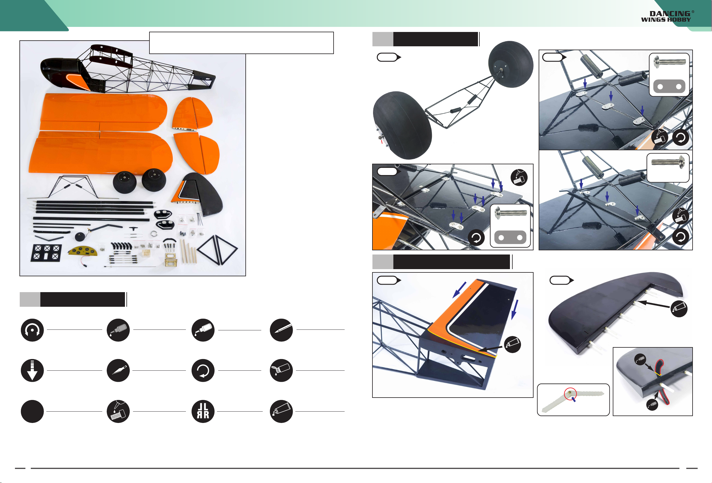
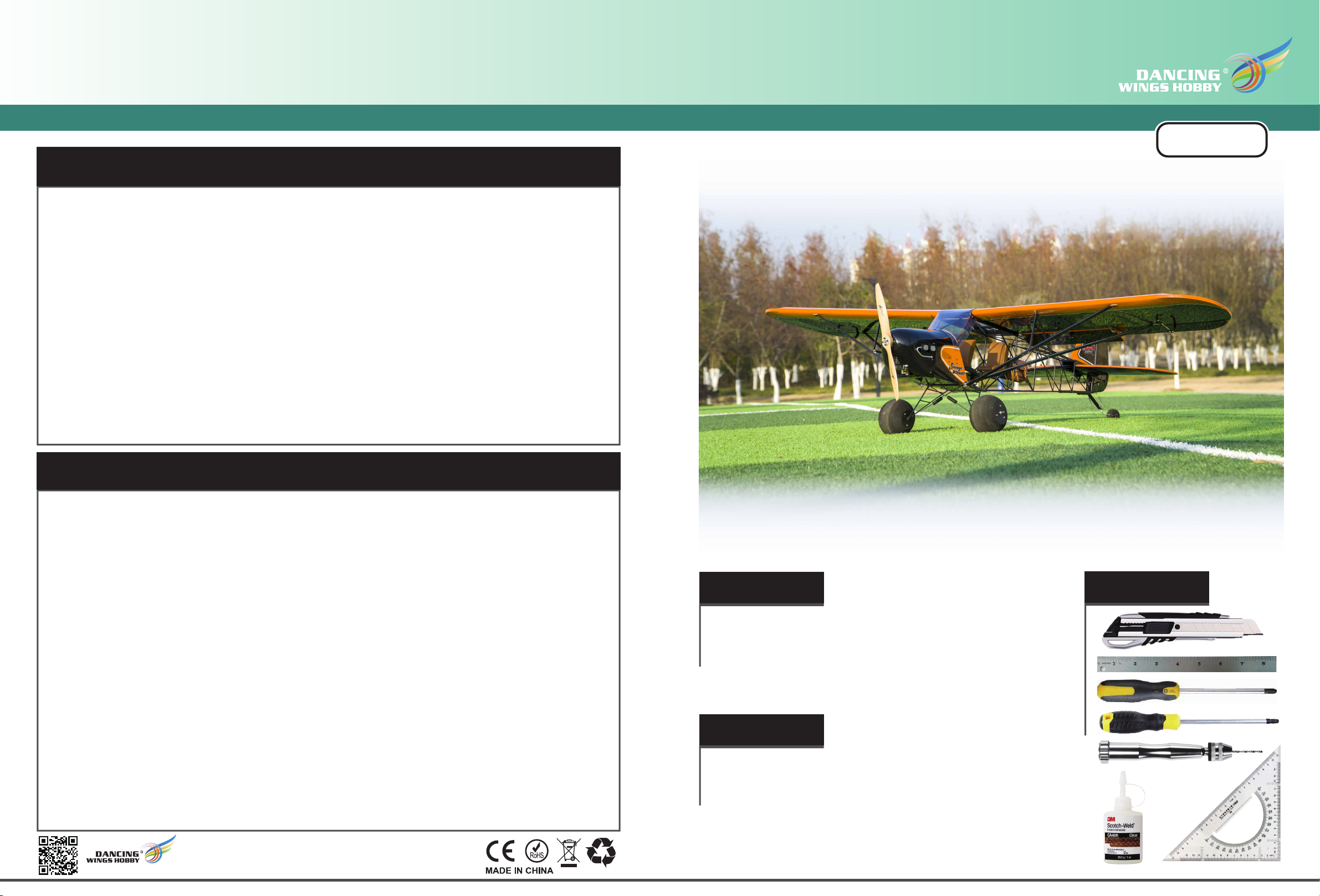
Balsawood Scale Airplane
● This product should not be considered a toy, but rather a complicated and sophisticated flying model. Your safety depends
on how you use and fly it, If not correctly operated, could cause injury to you or your family members. Children must be
accompanied by an adult at all times if operating this product. Not suitable for children under the age of 14. THIS IS NOT A
TOY.
● Do not fly around some restricted location like airports, military bases, residential areas, etc.
● You will need to range check the transmitter to be sure you are not experiencing any interference.
● Always turn on the receiver last after turning on the transmitter and shut off the receiver first before turning off the transmitter.
● If you are only a beginner to the radio control model flying, do not attempt to fly your model without any assistance or advice from
advanced expert fliers.
● Keep relevant items out of reach of children.
● This product has been flight tested to meet or exceed our rigid performance and reliability standards in normal use,if you plan to perform
any high-stress flying, you are solely responsible for taking any and all necessary steps to control movement range and reinforce the body
strength.
● This product may include some fiberglass and carbon-fiber reinforced plastic parts,which may cause eye and skin discomfort,pls wear the
goggles or dust-proof clothes when needed.
● Due to air traffic safety control, the products you receive may not have the glue that appears in the list. Please understand and purchase the
glue you need at your local stationery store.
SAFETY PRECAUTIONS
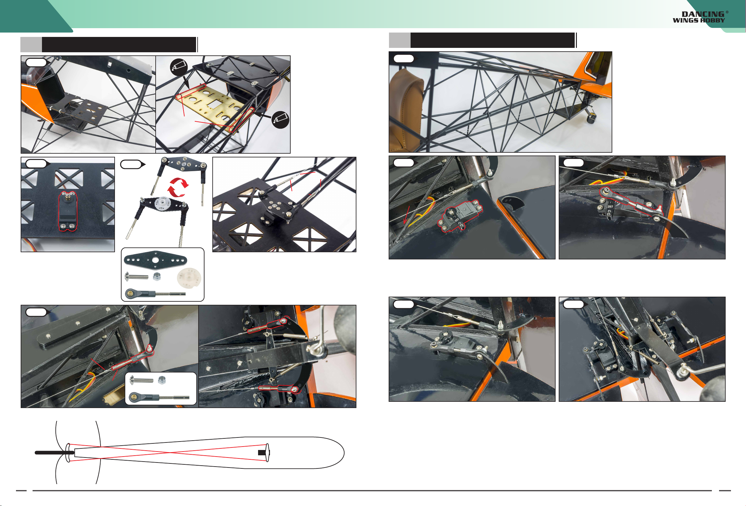
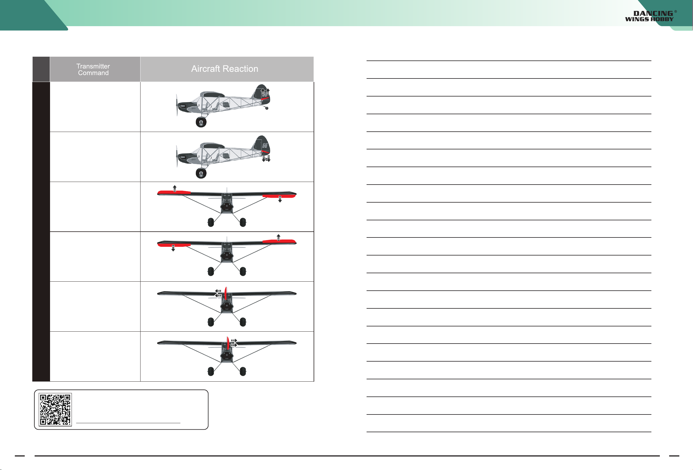
● Check/adjust servo centering, in order to adjust the control surface better.
● Double-check the spinning direction of motor at first usage, and sure it’s suitable for your model.
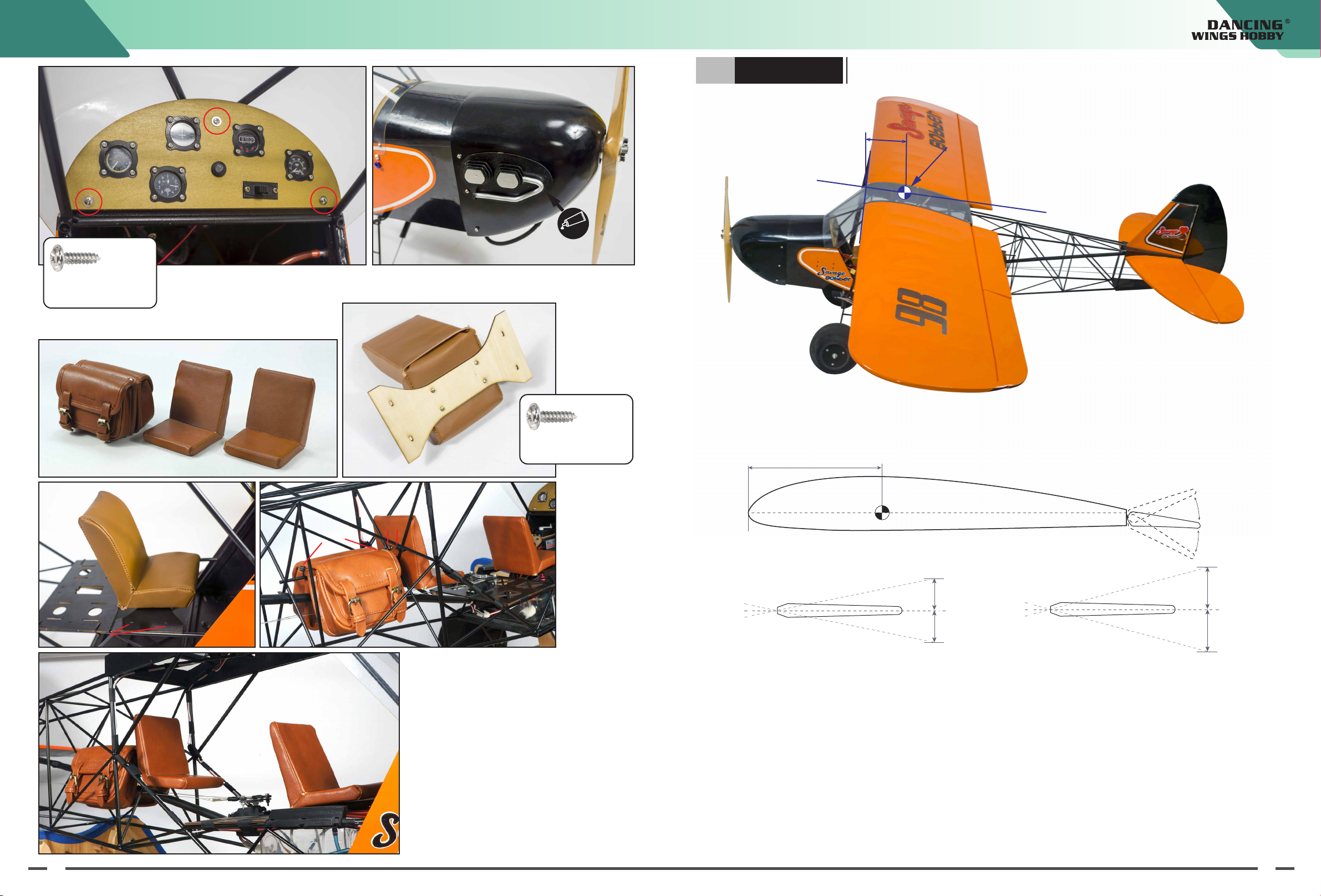
● Set the center of gravity (CG) at the position that manual already marked out. If necessary, add weight to the nose or tail
to ensure the best flight performance.
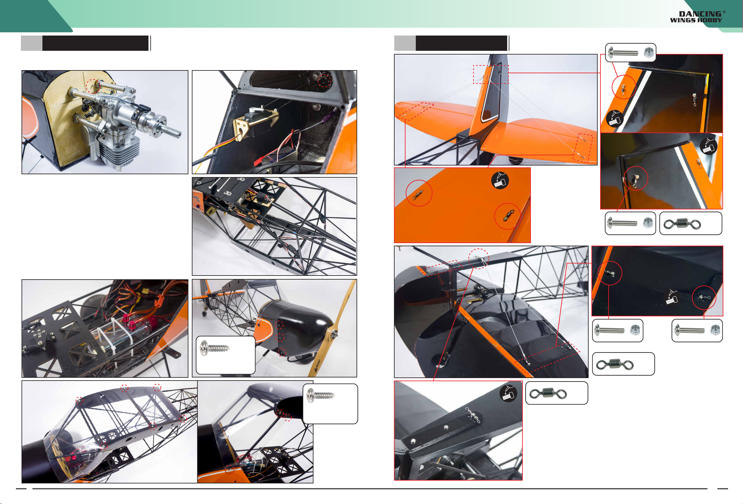
● Double-check the inside of the fuselage, make sure all the equipments are correctly connected; Check the heat-shrink
covering material’s surface, Make certain all screws, bolts, cabin and canopy remain secure.
● Take great care when connecting/disconnecting the battery, pls replace the battery immediately once found low voltage
or damage to battery.
● The way the internal devices of the fuselage are connected will be related to your transmitter-receiver device. For those
transmitter-receiver devices with more functions, you can simplify the connection of the internal devices of the fuselage.
Check your device for details to see if it meets the features you need.
● When the power system and transmitter-receiver device are paired for the first time, you may need to set the maximum
stroke of the throttle. Please set it yourself.
PRE-FLIGHT CHECKS
http://www.dwhobby.com/
SCG40
Tools Needed
Specification
Suggested Equipment
ARF
Wingspan:2.33M (92inch)
Fuselage Length:1.7M (67inch)
Flying weight:≈8.0kg (About 280pound)
Engine:RCGF 35cc
Prop:20inch
Servo:37g*8pcs

Use epoxy adhesive
★Assembly symbol guide
Ensure free rotation Use medium CA Use a pencil
Use thin CA
Push tightly Use hobby knife with
OIL
Apply OilFully Tighten
Apply threadlock Assemble right
and left Epoxy glue
Repeat multiple times
x2
KIT Photos shown here just for reference, the product you received maybe slightly
differ from the photos due to continuous improvement on products.
21
01 Assemble the Landing Gear
01-1
SCG40-B: Wing
SCG40-D: Horizontal tail
SCG40-C: Vertical tail
F1-2: Landing Gear
F3: Wheels
SCG40-K: Carbon tube
G1-2: Tail wheel
H1-3: Wing support
P: Servo mounting plate
SCG40-I: Scale dashboard
J: Rudder horn
O: Steel wire connecting rod
Q1-2: Block,Wooden pole
SCG40-L: Throttle linkage
M: Scale engine
N: Servo seat
SCG40-A: Fuselage
wheel stopper
wheel stopper
SCG40-A
SCG40-E
SCG40-B SCG40-D
SCG40-C
SCG40-K
SCG40-I
F1 F3
F2
H1
H2
H3
M
N
G1
P
J
O
L
O
Q1
Q2
G2
02 Assemble the Tail Wing and Tail Wheel
Screws and accessories
SCG40-E: Cowling
01-2
01-3 Screw
M3x15mm
Epoxy glue
02-1 02-2
Epoxy glue
Add some lubricating oil in the joint of needle type hinge.(Avoid
the glue stuck dead.)
Before install and fasten needle type hinge with epoxide-resin
glue , please confirm the surface can swing freely in advance.
Lubricant oil
Note: The installation of this hinges in subsequent steps requires the
same operation
Install the vertical tail to the rear of the fuselage and glue firmly with
a lot of epoxy glue.
Screw
M3x15mm
Screw
M3x15mm
F1
F3
F3
F2
Rudder horn
SCG40-C

03 Assemble the Wing
43
When steps 02-8 and 02-9 are fixed with self-tapping screws,
drill holes at the pre installed hole position with a drill bit.
When installing the flap, drill holes in the reserved screw holes, and
then tap a small amount of CA glue. After curing, screw in the
self-tapping screws to install the hinges, so that the flaps can swing
freely.
Install the servo horn at the servo horn holes of the aileron
and flap. As shown in the figure below.
10mm
02-3 02-4
02-5
02-6 02-7
02-8 02-9
Epoxy glue
Lubricant oil
Lubricant oil
Adjust to be
perpendicular to
each other
Spring
Spring
02-10
03-2
03-3
03-1
Self-tapping screw
M3x10mm
Self-tapping screw
M3x20mm
G1
G2
G2
Epoxy glue
Epoxy glue
Epoxy glue
Aileron
Flap
Self-tapping screw
M2x10mm
03-4
Hand screw
M4x20mm
M2
M1.5
Ø10x270mm
SCG40-D
SCG40-B
Aileron Flap

6
5
Remove the servo compartment
cover from the wing,
and install the servos between
the small wooden blocks. When
installing the rudder arm, power
on the servos back to the center.
Pass the servo wires into the
wing and lead out from the side
of the wing,The same opration
for two servos.
1.Install the servo compartment cover and fix it with self tapping screws
2.Then adjust the connecting rod to the appropriate length, and connect the connecting
rod to the servo horn
Install wing braces
G3 Details
M3*15mm+Self locking nut
M3*15mm
03-5
03-6
03-7
03-8
H3
H3
H3
H2 Short
LongH1
M3*15mm+Self locking nut
M3*10mm+Self locking nut
G2 Details
G1 Details There are
reserved screw
holes in the
corresponding
positions of the
picture,
and screw in
plastic screws to
fix G1 and G2.
Hand screw
M4x15mm
Hand screw
M4x30mm
Hand screw
M4x15mm
Details1
Details2
H1
H1
H2
H2
F2 F2
Nut
Details2
Details1
Self locking nut
03-9 03-10
Self-tapping screw
M3x10mm
Ø20x780mm
Ø10x380mm
Q1
Q1
Carbon rod
Carbon rod

8
7
04 Install the rudder steering gear and connecting rod
04-1
04-2 04-3
05 Install the elevator steering gear and connecting rod
05-1
05-2 05-3
05-4 05-5
M3*15mm+Self-locking nut
M3*18mm+Self-locking nut
Install the servo seat at the
corresponding position in
the picture, fix the reverse
side with wooden rod and
black tie, and fix it with a
large amount of epoxy
resin adhesive.
Install the servo in the servo
position and fix it with screws.
Install the servo arm on the servo and fix it with screws.
And install the steel wire stay wire.Here are 2 steel wires
controlling the steering rudder.
Place a conduit inside the fuselage as shown
in the figure on the left, the conduit is spliced
by three short tubes. Fix it on the fuselage
frame with a tie.
Install the servo in the servo hole of the horizontal tail and install
the servo arm. The servo wire is led into the conduit placed in the
previous step and led out from the other end. The left and right are
the same.
Install the connecting rod on the servo arm and rotate the
connecting rod to adjust to the proper length
Connect the connecting rod to the servo arm, and tighten the
screws to fix it.
The left and right servo control groups are installed in the same
way.
The other end of the steel wire is connected to the servo arm
of the rudder as shown in the figure.
The two steel wire connecting rods are installed in the same
way, and the wires are kept tight after installation.
Two steel wire connecting rods are installed in an X-shaped
cross.
Black
cable ties
Q2 Wooden rod
Q2 Wooden rod
Assemble the rudder
arm as shown
Alu. buckle
wire penetration
Lead in servo wire
Alu. buckle
Epoxy glue
Epoxy glue
P
P
04-5
wire penetration
Black cable ties
Black cable ties

10
9
07 Display the wiring for wing
06 Install the Motor and Cowling
Here is a demonstration of the engine installation location and the arrangement of electronic equipment and wires, and you can also
arrange a reasonable location by yourself.
Note: When installing the engine, please adjust the right
pull-down angle 3° and pull-down angle 4°.
The throttle cable is
drilled through
Throttle cable servo installation positionEngine installation display
The throttle cable
controls the servo
Steering gear wiring demonstration
Oil tank position (same as C.G. )
Self-tapping screw
M3x10mm
Self-tapping screw
M2 x10mm
Screw M2*25mm+Nut
Screw M2*15mm+Nut
Screw M2*25mm+Nut Screw M2*20mm+Nut
X2
Install the cable buckle at
the reserved hole position
shown in the figure.
Install the cable buckle at the reserved hole
position shown in the figure.
Cut the stay wire according to the length, thread it
into the pull ring, and clamp and fix it with aluminum
buckle.
Cut the stay wire according
to the length, thread it into
the pull ring, and clamp
and fix it with aluminum
buckle.
X2
X2
Front of horizontal tail
Back of the horizontal tail

08 Set and Adjust
Display the C.G
Normal Flying 3D Flying only support some models
Aileron ±(15°-30°) ±40° or larger
Elevator ±15° ±40° or larger
Rudder ±15° ±40° or larger
Flap take-off 15°-20° Landing 20°-40°
Some special models will have V-tails, flaps, leading edge wings, etc., which can be used as a reference for conventional
flight angles. If you do not confirm and there is no experienced person to guide you, we recommend that you first test
at a small angle to confirm that your settings are correct.
Rudder
Elevator
Aileron
20°-35°
25°
25°
25°
25°
20°-35°
Usually, the control throws set as below:
≈150mm
C.G
≈150mm
1211
Self-tapping screw
M3x10mm
Self-tapping screw
M3x10mm
Cable ties
Cable ties
Cable ties
Installation of optional seats and tool kits
Epoxy glue
SCG40-I
M

NOTE:
14
13
More details about power system adjustment, please refer
to below link: (You can scan QR Code directly.)
http://www.dwhobby.com/art/connection
Control Directions Tests
ElevatorAileronRudder
Direction rod to the left
Direction rod to the right
Steering rod to the left
Steering rod to the right
Lifting rod up
Lifting rod down
This manual suits for next models
1
Other Dancing Wings Hobby Aircraft manuals
Popular Aircraft manuals by other brands

Mooney Aircraft
Mooney Aircraft MARK 21 owner's manual

Rans
Rans S-12S quick start guide

Carl Goldberg Products
Carl Goldberg Products TIGER 2 instruction manual

Piper Aircraft Corporation
Piper Aircraft Corporation PA-28-161 CADET Maintenance manual

Wills Wing
Wills Wing RamAir 154 Owner's service manual

Remos
Remos GXiS Pilot operating handbook