HELIX V3 User guide

Copyright 2012 Gregory Bartlett
11/10/2014
Helix Light Controller
Helix V3 Main Board
Assembly and Setup Manual

Helix Main Board
Assembly and Setup Manual
1
Comments, Questions or Concerns contact the developer at: Greg@helixlightcontroller.com
Table of Contents
Overview.................................................................................................................................................... 2
Helix Main Board Bill Of Materials (BOM) ................................................................................................... 3
Helix Main BOM Continued .................................................................................................................... 4
Initial Assembly of the Main Board ............................................................................................................. 5
Step-by-Step Instructions (Table 1 of 3) .................................................................................................. 5
Step-by-Step Instructions (Table 2 of 3) .................................................................................................. 6
Step-by-Step Instructions (Table 3 of 3) .................................................................................................. 7
Pictorial Assembly (1 of 7): RTC Crystal and Resistors (Steps 1-13) ......................................................... 8
Pictorial Assembly (2 of 7): Resistors, Diodes, Crystal and Sockets (Steps 14-30) .................................... 9
Pictorial Assembly (3 of 7): LEDs (Steps 31-45) ..................................................................................... 10
Pictorial Assembly (4 of 7): SIP Resistors and Bypass Caps (Steps 46-61) .............................................. 11
Pictorial Assembly (5 of 7): IC Sockets, Switch and MOSFET (Steps 62-73) ............................................ 12
Pictorial Assembly (6 of 7): Headers, MP3 Sockets and Fuse Clips (Steps 74-86) ................................... 13
Pictorial Assembly (7 of 7): Remaining Components (Steps 87-110) ..................................................... 14
Assembly Notes.................................................................................................................................... 15
Assembly Pictures................................................................................................................................. 17
Initial Power Up of the Main Board........................................................................................................... 18
Assembly of the MP3 Board...................................................................................................................... 19
Final Assembly of the Main Board............................................................................................................. 20
Final Assembly Steps ............................................................................................................................ 20
Configuration of the MicroSD Card ........................................................................................................... 21
Initial Testing of the Main Board............................................................................................................... 23
Final Testing of the Helix Network Controller Board.................................................................................. 24
MicroSD Card and MP3 Player Test....................................................................................................... 24
Test and Setup of the Real Time Clock .................................................................................................. 24
Helix Network Controller Calibration .................................................................................................... 27
Final Testing of the Network Node Board ................................................................................................. 28
XBee Configuration and MicroSD Card Test........................................................................................... 28
Setup of the Helix Main Board.................................................................................................................. 29
Custom Cable Pin-outs ............................................................................................................................. 30

Helix Main Board
Assembly and Setup Manual
2
Comments, Questions or Concerns contact the developer at: Greg@helixlightcontroller.com
Overview
This is the basic assembly and setup instructions for the Helix Main Board v2. It is not the purpose of this document
to teach soldering techniques or basic electronics. If you need assistance in this area there are several other sources
on the internet for this type of information.
The Helix Main Board can be assembled in two different configurations. The first configuration is as the Helix
Network Controller. There is only one Helix Network Controller in a Helix Network. The Network Controller is
responsible for starting/stopping the show, playing the MP3 songs and providing the synchronization pulses to the
other controllers.
The second configuration is the Helix Network Node. All Helix Main Boards that are not the Helix Network Controller
are Helix Network Nodes. The Network Node doesn’t have the Real Time Clock (RTC) or the MP3 player. In the
assembly notes the parts that are not needed in a Network Node are identified.
The assembly and setup will follow these steps:
1) Initial assembly of the main board
2) Initial power up of the main board
3) Assembly of the MP3 player
4) Final assembly of the main board
5) Configuration of the MicroSD Card
6) Initial testing of the main board
7) Final testing of the Helix Network Controller or Helix Network Node
The Helix Main Board is fairly complicated to assemble. If you have little experience with PCB assembly you may
want to consider assembling the Helix Daughter Board first.
If you have any suggestions or problems with this manual or assembly of the Helix Main Board please
email the developer at: Greg@helixlightcontroller.com
Helix Main Board
Assembly and Setup Manual
3
Comments, Questions or Concerns contact the developer at: Greg@helixlightcontroller.com
Helix Main Board Bill Of Materials (BOM)
Part
Description
Supplier
Part#
Qty
Notes
AJ1
3.5 mm Vertical Jack
Mouser
161-0352-EX
1
AJ1 Not needed on HNN
B1
Battery Holder
Mouser
614-VBH2032-1
1
B1 is not needed on Helix
Network Node (HNN)
C1, C2, C3, C4, C5,
C6, C7, C8, C9, C10,
C11
0.1 uF Bypass Cap
Mouser
75-1C10Z5U104M050B
11
C1 and C11 are not
needed on a HNN
C12
33pF Timing Cap
Mouser
80-C323C330K2G
1
C13
4700 uF Filter Cap
Mouser
647-UVZ1C472MHD
1
C14, C15
100 uF Filter Cap
Mouser
647-UVR1E101MED1TD
2
D1, D2, D3, D4, D5
1N5817
Mouser
821-1N5817
5
D3, D4 not needed HNN
D6, D8, D10, D13
RED LED
Mouser
859-LTL42EKEKNN
4
D7, D12, D15, D16,
D17, D18, D19
GREEN LED
Mouser
859-LTL-4236N
7
D9, D11, D14
YELLOW LED
Mouser
859-LTL1CHKYKNN
3
F1
FUSE Horizontal
Mouser
534-3517
2
H1, H2, H3, H4, H7,
H8, H9
0.1" Pin Strip Header 40
Pin
Mouser
517-6111TG
1
H5, H6
0.1" Pin Strip Header 5
Pin
Mouser
517-929834-01-05-RK
1
H5, H6 not needed on
HNN
IC1
DS1337
Mouser
700-DS1337
1
IC1 not needed on HNN
IC2
24LC256
Provided with the PCB
IC3
H11AA1-M
Mouser
512-H11AA1M
1
IC4, IC5, IC6, IC7
SN75174NE4
Mouser
595-SN75174NE4
4
IC8
Propeller
Mouser
619-P8X32A-D40
1
IC9
MCP23016
Mouser
579-MCP23016-I/SP
1
IC10
ST485
Provided with the PCB
J1, J2, J3, J4, J5, J6
RJ45
Mouser
571-5556416-1
6
MP3
MP3 Breakout Board
SparkFun
BOB-09943
1
MP3 not needed on HNN
NE1
NE-2 Neon Lamp
Mouser
606-A9A
1
Q1
TN0702N3-G
Mouser
689-TN0702N3-G
1
Q1 not needed on HNN
R1, R2, R3, R4, R5,
R6, R7
220 ohm Resistor
Mouser
291-220-RC
7
R8
100 ohm Resistor
Mouser
291-100-RC
1
R9, R10
510 ohm Resistor
Mouser
291-510-RC
2
R11, R12
1K ohm Resistor
Mouser
291-1K-RC
2
R13
3.9K ohm Resistor
Mouser
291-3.9K-RC
1
R14, R15, R16, R17,
R18, R19, R20
10K ohm Resistor
Mouser
291-10K-RC
7
R19 not needed on HNN
R21
100K ohm Resistor
Mouser
291-100K-RC
1
330K ohm for 220VAC
RA1
10K ohm SIP Resistor (8)
Mouser
858-L091S103LF
1
RA1 not needed on HNN
RA2
1K ohm SIP Resistor (8)
Mouser
858-L091S102LF
1
RA2 not needed on HNN
RA3
220 ohm SIP Resistor (7)
Mouser
858-L081S221LF
1
RA4
47K ohm SIP Resistor (5)
Mouser
858-L061S473LF
1
S1
MicroSD Socket
Provided with the PCB
SW1
Tactile Switch
Mouser
611-PTS645SL702
1
T1
6.3V 1A Transformer
Mouser
838-3FD-412
1
TB1, TB2, TB3, TB4,
TB5, TB6, TB7, TB8,
TB9
2 POS 5mm Terminal
Block
Mouser
651-1935161 or 571-
2828372
9
TB2, TB3, TB4, TB5, TB6,
TB7, TB8 and TB9 not
needed on HNN
U1
5V Regulator
Mouser
511-LD1085V50
1
U2
3.3V Regulator
Mouser
926-LMS1585ACT33NOPB
1
U3
DB101
Mouser
583-DB101
1
XTAL1
32.768KHz Crystal
Mouser
695-CFS206-327KB-U
1
XTAL1 not needed HNN
XTAL2
5MHz Crystal
Mouser
520-HCU500-20X
1
Helix Main Board
Assembly and Setup Manual
4
Comments, Questions or Concerns contact the developer at: Greg@helixlightcontroller.com
Helix Main BOM Continued
Misc Other Parts
Part
Description
Supplier
Part#
Qty
Notes
B1
CR2032 Lithium Coin Cell
Mouser
614-CR2032-MFR
1
B1 not needed on HNN
IC4, IC5, IC6, IC7
16p DIP Socket
Mouser
571-1-2199298-4
4
IC8
40p DIP Socket
Mouser
571-1-2199299-5
1
IC1, IC2, IC10
8p DIP Socket
Mouser
571-1-2199298-2
3
IC1 not needed on HNN
IC3
6p DIP Socket
Mouser
571-1-2199298-1
1
IC9
28p DIP Socket
Mouser
571-1-2199298-9
1
F1
1A 5x20mm Fast Blow
Fuse
Mouser
576-0217001.MXP
1
F1
Fuse Cover
Mouser
534-3527C
1
H1^2, H3, H4, H7,
H8, H9
0.1" Shunt 1A
Mouser
151-8010-E
7
MP3
0.1" PCB Mount Socket
20 Position
Mouser
517-929850-01-20-RB
1
MP3 not needed on HNN
U1, U2
TO-220 Heatsink
Mouser
532-579302B00
2
Recommended Spacers
Mouser
561-KSP117
4
USB to RS485 Option
If you plan to use the board in a wired configuration only then you will need one set of the following parts.
Part
Description
Supplier
Part#
Qty
Notes
RS1
USB to RS485
SparkFun
BOB-09822
1
Not needed on HNN
USB miniB Cable
SparkFun
CAB-00598
1
Not needed on HNN
J7
RJ45
Mouser
571-5556416-1
1
Not needed on HNN
XBee Wireless Option
If you plan to use the board in a wireless configuration then you will need one set of the following parts.
Part
Description
Supplier
Part#
Qty
Notes
RF1
XBEE PRO
Mouser
888-XBP24-AWI-001
2
Only 1 needed on HNN
RF1
2mm Pitch SIP Socket
10p
SparkFun
PRT-08272
2
XBee Explorer USB
SparkFun
WRL-11812
1
Not needed on HNN
USB miniB Cable
SparkFun
CAB-00598
1
Not needed on HNN
If you have any questions about the wired or wireless options please contact the developer at
Greg@helixlightcontroller.com before you place your order.

Helix Main Board
Assembly and Setup Manual
5
Comments, Questions or Concerns contact the developer at: Greg@helixlightcontroller.com
Initial Assembly of the Main Board
The initial assembly of the main board will consist of soldering all of the major components to the PCB, starting with
the components that have the lowest profile and finishing with the ones with the highest profile. Two methods of
assembly are presented in this manual. This first is a table with the step-by-step instructions and associated notes.
The second is a series of pictures of the main board’s silk screen with arrows and notes pointing to each step. Each
method shares the same notes and pictures. Use whichever method works best for you.
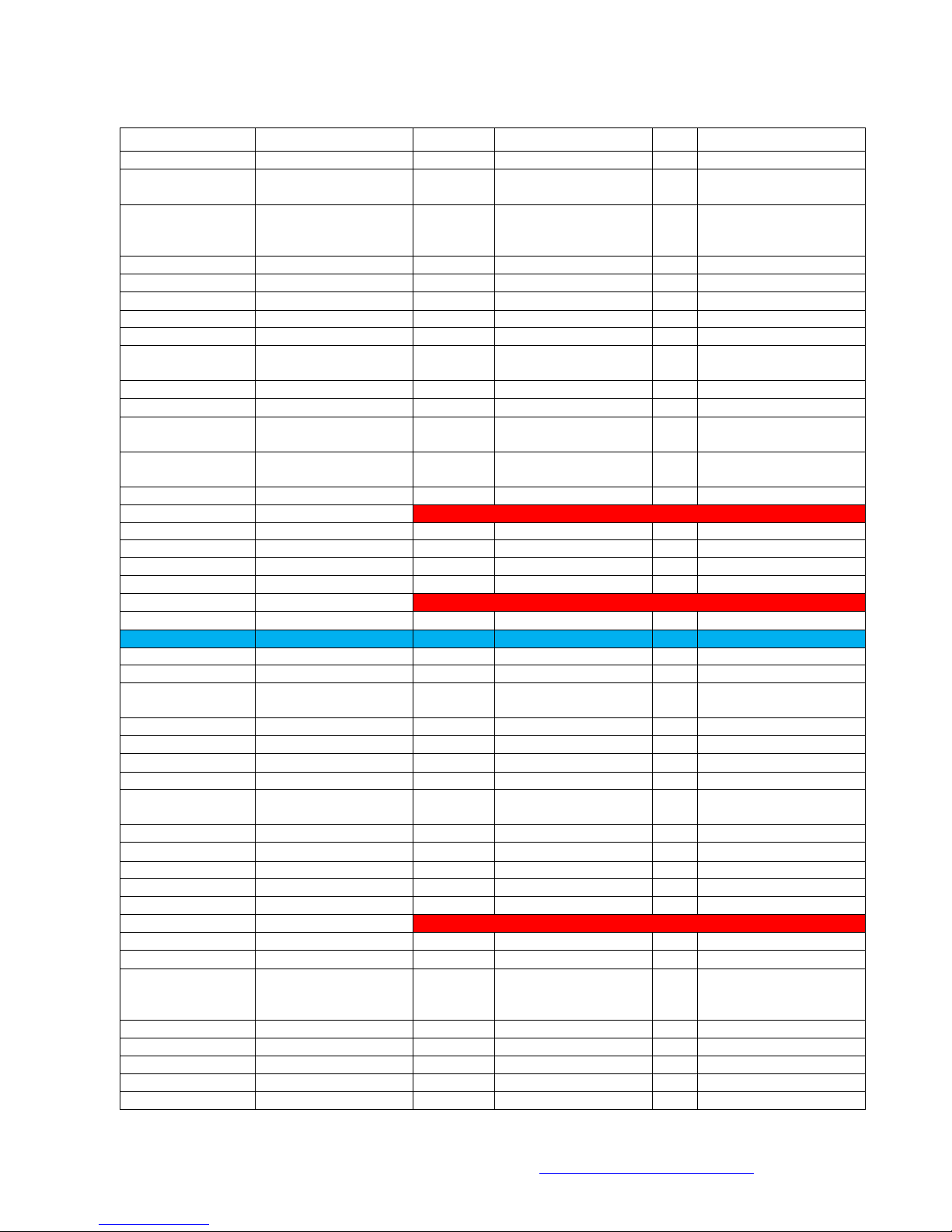
Step-by-Step Instructions (Table 1 of 3)
Step
Done
Ref Number
Value
Note
1
XTAL1
32.768 KHz
See Note 1; RTC Crystal; Not needed on Network Node
2
R1
220
Red, Red, Brn
3
R2
220
Red, Red, Brn
4
R3
220
Red, Red, Brn
5
R4
220
Red, Red, Brn
6
R5
220
Red, Red, Brn
7
R6
220
Red, Red, Brn
8
R7
220
Red, Red, Brn
9
R8
100
Brn, Blk, Brn
10
R9
510
Grn, Brn, Brn
11
R10
510
Grn, Brn, Brn
12
R11
1 K
Brn, Blk, Red
13
R12
1 K
Brn, Blk, Red
14
R13
3.9 K
Orn, Wht, Red
15
R14
10 K
Brn, Blk, Orn
16
R15
10 K
Brn, Blk, Orn
17
R16
10 K
Brn, Blk, Orn
18
R17
10 K
Brn, Blk, Orn
19
R18
10 K
Brn, Blk, Orn
20
R19
10 K
Brn, Blk, Orn; Not needed on Network Node
21
R20
10 K
Brn, Blk, Orn
22
R21
100 K
Brn, Blk, Yel
23
D1
1N5817
See Note 2
24
D2
1N5817
See Note 2
25
D3
1N5817
See Note 2; Not needed on Network Node
26
D4
1N5817
See Note 2; Not needed on Network Node
27
D5
1N5817
See Note 2
28
XTAL2
5 MHz
See Note 3; Propeller Chip Crystal
29
U3
DB101
See Note 4
30
RF1 Left Socket
10p SIP Socket
See Note 5; 2mm Pitch
31
RF1 Right Socket
10p SIP Socket
See Note 5; 2mm Pitch
32
D6
Red T-1 (3mm) LED
See Note 6
33
D8
Red T-1 (3mm) LED
See Note 6
34
D10
Red T-1 (3mm) LED
See Note 6
35
D13
Red T-1 (3mm) LED
See Note 6
36
D7
Grn T-1 (3mm) LED
See Note 6
37
D12
Grn T-1 (3mm) LED
See Note 6
38
D15
Grn T-1 (3mm) LED
See Note 6
39
D16
Grn T-1 (3mm) LED
See Note 6
40
D17
Grn T-1 (3mm) LED
See Note 6

Helix Main Board
Assembly and Setup Manual
6
Comments, Questions or Concerns contact the developer at: Greg@helixlightcontroller.com
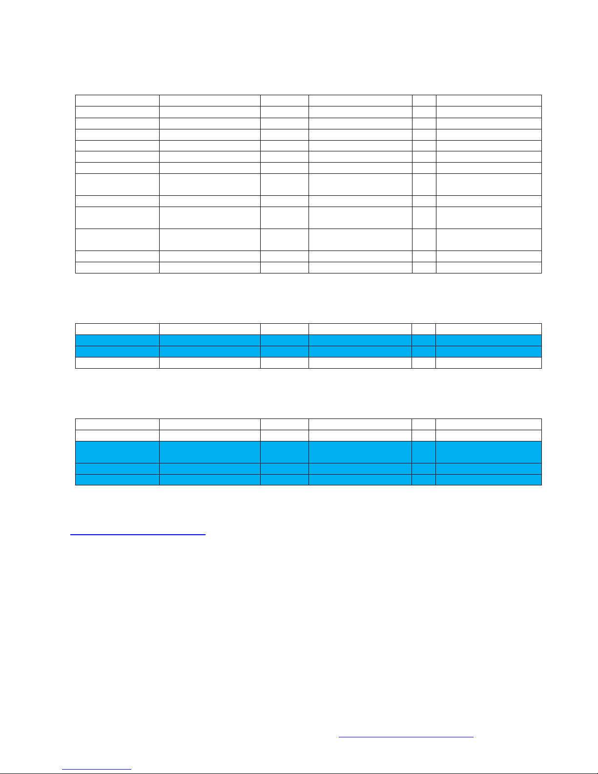
Step-by-Step Instructions (Table 2 of 3)
Step
Done
Ref Number
Value
Note
41
D18
Grn T-1 (3mm) LED
See Note 6
42
D19
Grn T-1 (3mm) LED
See Note 6
43
D9
Yel T-1 (3mm) LED
See Note 6
44
D11
Yel T-1 (3mm) LED
See Note 6
45
D14
Yel T-1 (3mm) LED
See Note 6
46
RA1
10 KSIP Resistor
See Note 7; Not needed on Network Node
47
RA2
1 KSIP Resistor
See Note 7; Not needed on Network Node
48
RA3
220 SIP Resistor
See Note 7
49
RA4
47 KSIP Resistor
See Note 7
50
C1
0.1 F
Not needed on Network Node
51
C2
0.1 F
52
C3
0.1 F
53
C4
0.1 F
54
C5
0.1 F
55
C6
0.1 F
56
C7
0.1 F
57
C8
0.1 F
58
C9
0.1 F
59
C10
0.1 F
60
C11
0.1 F
Not needed on Network Node
61
C12
33 pF
62
IC1 Socket
8p DIP Socket
See Note 8; Not needed on Network Node
63
IC2 Socket
8p DIP Socket
See Note 8
64
IC10 Socket
8p DIP Socket
See Note 8
65
IC3 Socket
6p DIP Socket
See Note 8
66
IC4 Socket
16p DIP Socket
See Note 8
67
IC5 Socket
16p DIP Socket
See Note 8
68
IC6 Socket
16p DIP Socket
See Note 8
69
IC7 Socket
16p DIP Socket
See Note 8
70
IC8 Socket
40p DIP Socket
See Note 8
71
IC9 Socket
28p DIP Socket
See Note 8
72
SW1
Tactile Switch
73
Q1
MOSFET
See Note 9; Not needed on Network Node
74
H1
4p Header
See Note 10
75
H2
4p Header
See Note 10
76
H3
3p Header
See Note 10
77
H4
3p Header
See Note 10
78
H5
3p Header
See Note 11; Not needed on Network Node
79
H6
2p Header
See Note 11; Not needed on Network Node
80
H7
2p Header
See Note 11
81
H8
2p Header
See Note 11
82
H9
2p Header
See Note 11
83
MP3 Left Socket
10p SIP Socket
See Note 12; 0.1” Pitch; Not needed on Network Node
84
MP3 Right Socket
10p SIP Socket
See Note 12; 0.1” Pitch; Not needed on Network Node
85
F1A
Fuse Clip
See Note 13
86
F1B
Fuse Clip
See Note 13
87
TB1
2p Terminal Block
AC Input; 0.2” Pitch
Helix Main Board
Assembly and Setup Manual
7
Comments, Questions or Concerns contact the developer at: Greg@helixlightcontroller.com
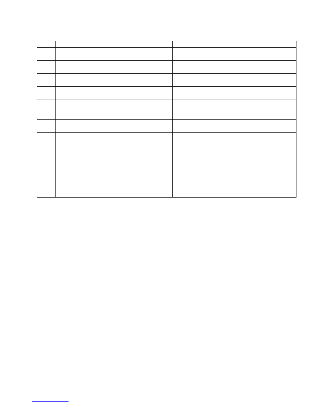
Step-by-Step Instructions (Table 3 of 3)
Step
Done
Ref Number
Value
Note
88
TB2
2p Terminal Block
See Note 14; Not needed on Network Node
89
TB3
2p Terminal Block
See Note 14; Not needed on Network Node
90
TB4
2p Terminal Block
See Note 14; Not needed on Network Node
91
TB5
2p Terminal Block
See Note 14; Not needed on Network Node
92
TB6
2p Terminal Block
See Note 14; Not needed on Network Node
93
TB7
2p Terminal Block
See Note 14; Not needed on Network Node
94
TB8
2p Terminal Block
See Note 14; Not needed on Network Node
95
TB9
2p Terminal Block
See Note 14; Not needed on Network Node
96
C14
100 F
See Note 15
97
C15
100 F
See Note 15
98
J1
RJ45 Jack
Cat 5 Jack
99
J2
RJ45 Jack
Cat 5 Jack
100
J3
RJ45 Jack
Cat 5 Jack
101
J4
RJ45 Jack
Cat 5 Jack
102
J5
RJ45 Jack
Cat 5 Jack
103
J6
RJ45 Jack
Cat 5 Jack
104
AJ1
Audio Jack
Stereo Audio Jack; Not needed on Network Node
105
NE1
Neon Bulb
106
U1
LD1085V50
See Note 16; 5V Regulator
107
U2
AP1084T33L
See Note 16; 3.3V Regulator
108
B1 Socket
Coin Cell Socket
Socket for 3V Coin Cell; Not needed on Network Node
109
C13
4700 F
See Note 15
110
T1
3FD-412
See Note 17; 6.3V Center Tap 1A Transformer

Helix Main Board
Assembly and Setup Manual
8
Comments, Questions or Concerns contact the developer at: Greg@helixlightcontroller.com
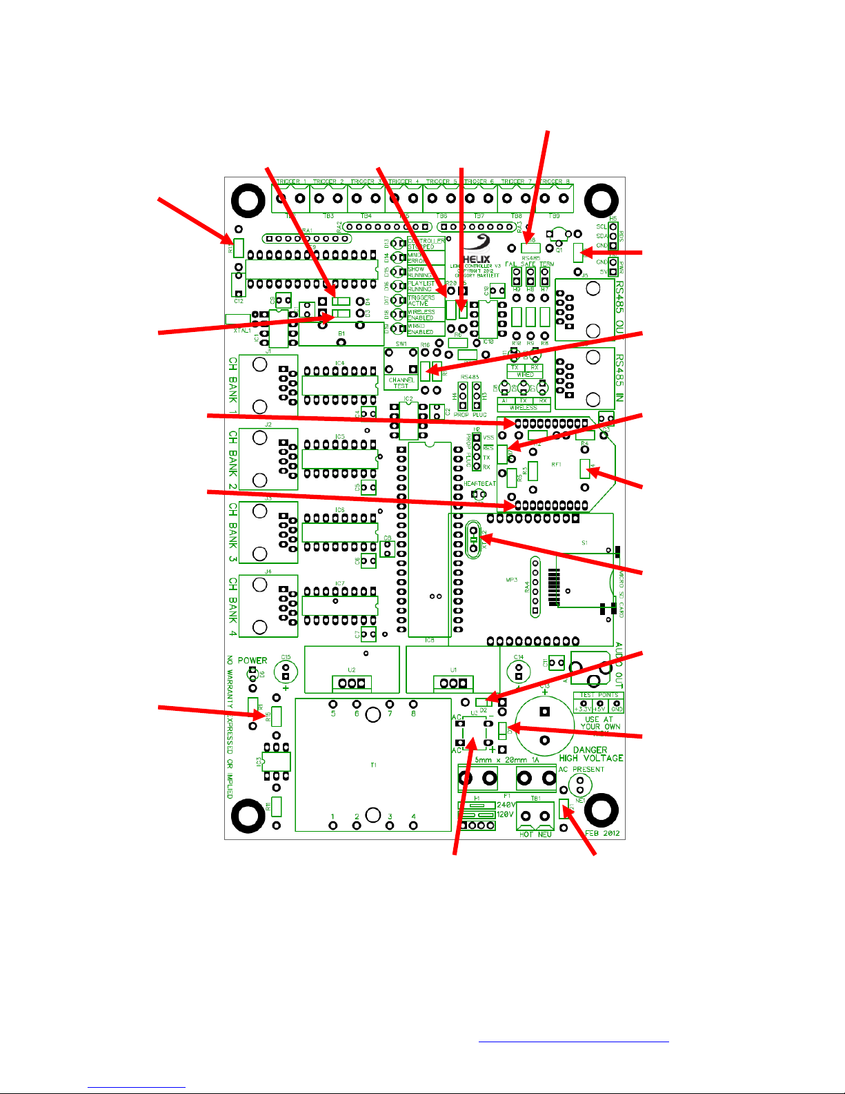
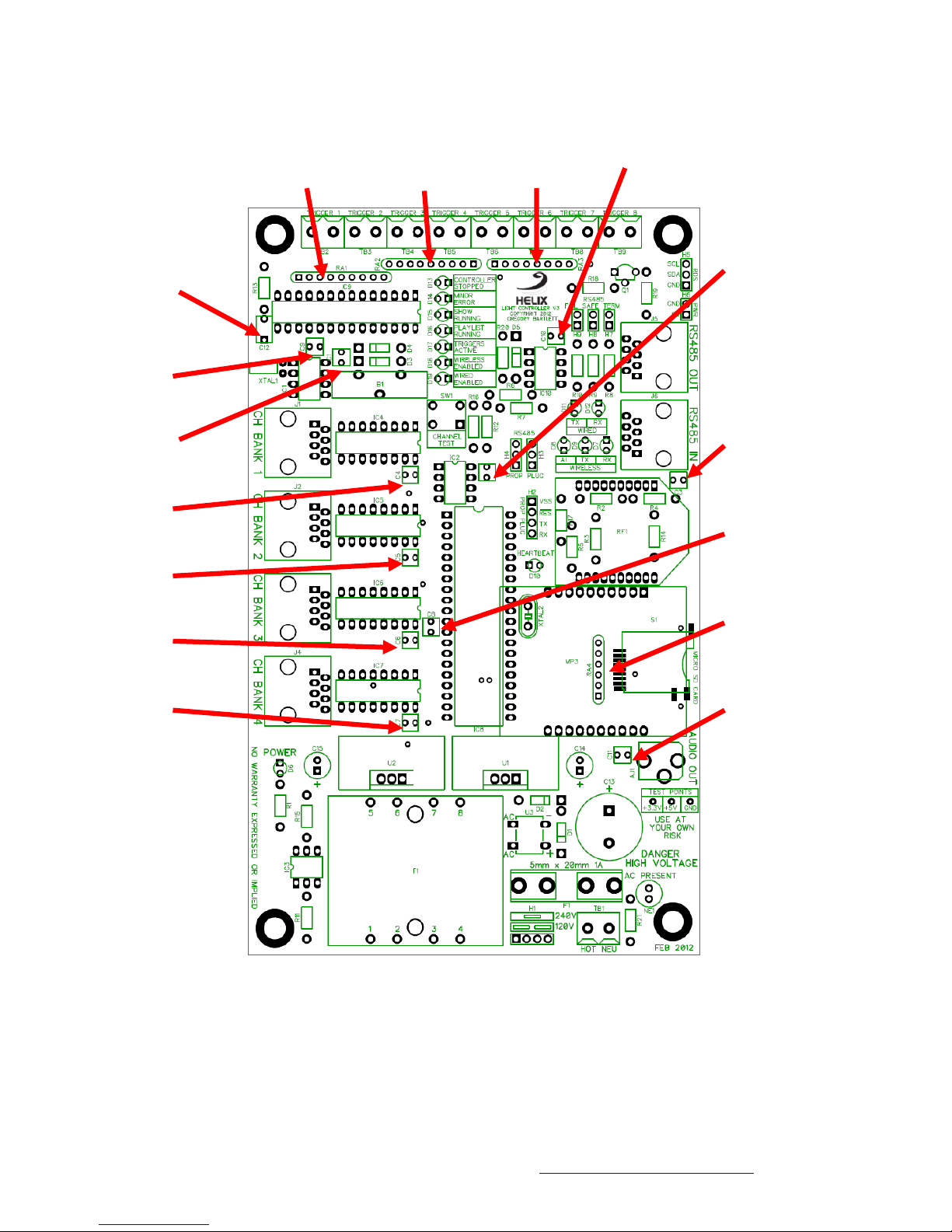
Pictorial Assembly (1 of 7): RTC Crystal and Resistors (Steps 1-13)
11 [ ] R10 10 [ ] R9
510 510
Grn, Brn, Brn Grn, Brn, Brn
7[ ] R6 9[ ] R8
220 100
Red, Red, Brn Brn, Blk, Brn
1[ ] XTAL1* 8[ ] R7
32.768 KHz 220
See Note 1 Red, Red, Brn
4[ ] R3 13 [ ] R12
220 1 K
Red, Red, Brn Brn, Blk, Red
6[ ] R5 5 [ ] R4
220 220
Red, Red, Brn Red, Red, Brn
3[ ] R2
220
Red, Red, Brn
2[ ] R1
220
Red, Red, Brn
12 [ ] R11
1 K
Brn, Blk, Red
* These parts are not needed on a Network Node Main Board
Helix Main Board
Assembly and Setup Manual
9
Comments, Questions or Concerns contact the developer at: Greg@helixlightcontroller.com
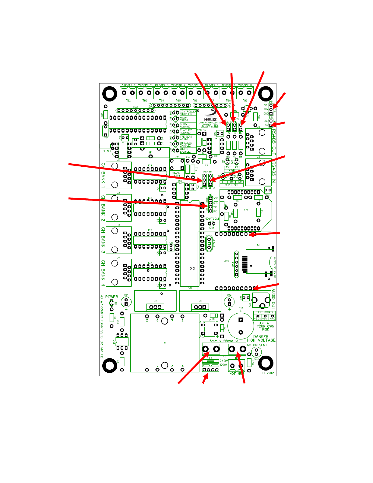
Pictorial Assembly (2 of 7): Resistors, Diodes, Crystal and Sockets (Steps 14-30)
26 [ ] D4* 21 [ ] R20 27 [ ] D5 19 [ ] R18
1N5817 10 K1N5817 10 K
See Note 2 Brn, Blk, Orn See Note 2 Brn, Blk, Orn
14 [ ] R13
3.9 K
Orn, Wht, Red
20 [ ] R19*
10 K
Brn, Blk, Orn
25 [ ] D3* 17 [ ] R16
1N5817 10 K
See Note 2 Brn, Blk, Orn
30 [ ] RF1 L Socket 18 [ ] R17
10p SIP 2mm Pitch 10 K
See Note 5 Brn, Blk, Orn
31 [ ] RF2 R Socket 15 [ ] R14
10p SIP 2mm Pitch 10 K
See Note 5 Brn, Blk, Orn
28[ ] XTAL2
5 MHz
See Note 3
24 [ ] D2
1N5817
See Note 2
16 [ ] R15
10 K 23 [ ] D1
Brn, Blk, Orn 1N5817
See Note 2
29 [ ] U3 22 [ ] R21
DB101 100 K
See Note 4 Brn, Blk, Yel
* These parts are not needed on a Network Node Main Board

Helix Main Board
Assembly and Setup Manual
10
Comments, Questions or Concerns contact the developer at: Greg@helixlightcontroller.com
Pictorial Assembly (3 of 7): LEDs (Steps 31-45)
35 [ ] D13 45 [ ] D14 38[ ] D15
Red LED Yellow LED Green LED
See Note 6 See Note 6 See Note 6
39 [ ] D16
Green LED
See Note 6
44 [ ] D11
40 [ ] D17 Yellow LED
Green LED See Note 6
See Note 6
37 [ ] D12
41 [ ] D18 Green LED
Green LED See Note 6
See Note 6
36 [ ] D7
42 [ ] D19 Green LED
Green LED See Note 6
See Note 6
43 [ ] D9
Yellow LED
See Note 6
33[ ] D8
Red LED
See Note 6
34 [ ] D10
Red LED
See Note 6
32 [ ] D6
Red LED
See Note 6
* These parts are not needed on a Network Node Main Board
Helix Main Board
Assembly and Setup Manual
11
Comments, Questions or Concerns contact the developer at: Greg@helixlightcontroller.com
Pictorial Assembly (4 of 7): SIP Resistors and Bypass Caps (Steps 46-61)
46 [ ] RA1* 47 [ ] RA2* 48 [ ] RA3 59[ ] C10
10 KSIP Res. 1 KSIP Res. 220 SIP Res. 0.1 F
See Note 7 See Note 7 See Note 7
51 [ ] C2
61 [ ] C12 0.1 F
33 pF
58 [ ] C9
0.1 F
50 [ ] C1* 52 [ ] C3
0.1 F 0.1 F
53 [ ] C4
0.1 F57 [ ] C8
0.1 F
54 [ ] C5
0.1 F
49 [ ] RA4
55 [ ] C6 47 KSIP Res.
0.1 F See Note 7
56 [ ] C7 60 [ ] C11*
0.1 F 0.1 F
* These parts are not needed on a Network Node Main Board

Helix Main Board
Assembly and Setup Manual
12
Comments, Questions or Concerns contact the developer at: Greg@helixlightcontroller.com
Pictorial Assembly (5 of 7): IC Sockets, Switch and MOSFET (Steps 62-73)
73 [ ] Q1*
MOSFET
See Note 9
64 [ ] IC10 Socket
71 [ ] IC 9 Socket 8p See Note 8
28p See Note 8
62 [ ] IC1 Socket* 72 [ ] SW1
8p See Note 8 Tactile Switch
66 [ ] IC4 Socket 63 [ ] IC2 Socket
16p See Note 8 8p See Note 8
67 [ ] IC5 Socket
16p See Note 8 70 [ ] IC8 Socket
40p See Note 8
68 [ ] IC6 Socket
16p See Note 8
69 [ ] IC7 Socket
16p See Note 8
65 [ ] IC3 Socket
6p See Note 8
* These parts are not needed on a Network Node Main Board
Helix Main Board
Assembly and Setup Manual
13
Comments, Questions or Concerns contact the developer at: Greg@helixlightcontroller.com
Pictorial Assembly (6 of 7): Headers, MP3 Sockets and Fuse Clips (Steps 74-86)
82 [ ] H9 81 [ ] H8 80 [ ] H7
2p Header 0.1" 2p Header 0.1" 2p Header 0.1"
See Note 10 See Note 10 See Note 10
78 [ ] H5*
3p Header 0.1"
See Note 11
79 [ ] H6*
2p Header 0.1"
See Note 11
76 [ ] H3
77 [ ] H4 3p Header 0.1"
3p Header 0.1" See Note 10
See Note 10
75 [ ] H2
4p Header 0.1"
See Note 10
83 [ ] MP3 L Socket*
10p SIP 0.1” Pitch
See Note 12
84 [ ] MP3 R Socket*
10p SIP 0.1” Pitch
See Note 12
85 [ ] F1A 74 [ ] H1 86 [ ] F1B
Fuse Clip 4p Header 0.1" Fuse Clip
See Note 13 See Note 10 See Note 13
* These parts are not needed on a Network Node Main Board
Helix Main Board
Assembly and Setup Manual
14
Comments, Questions or Concerns contact the developer at: Greg@helixlightcontroller.com
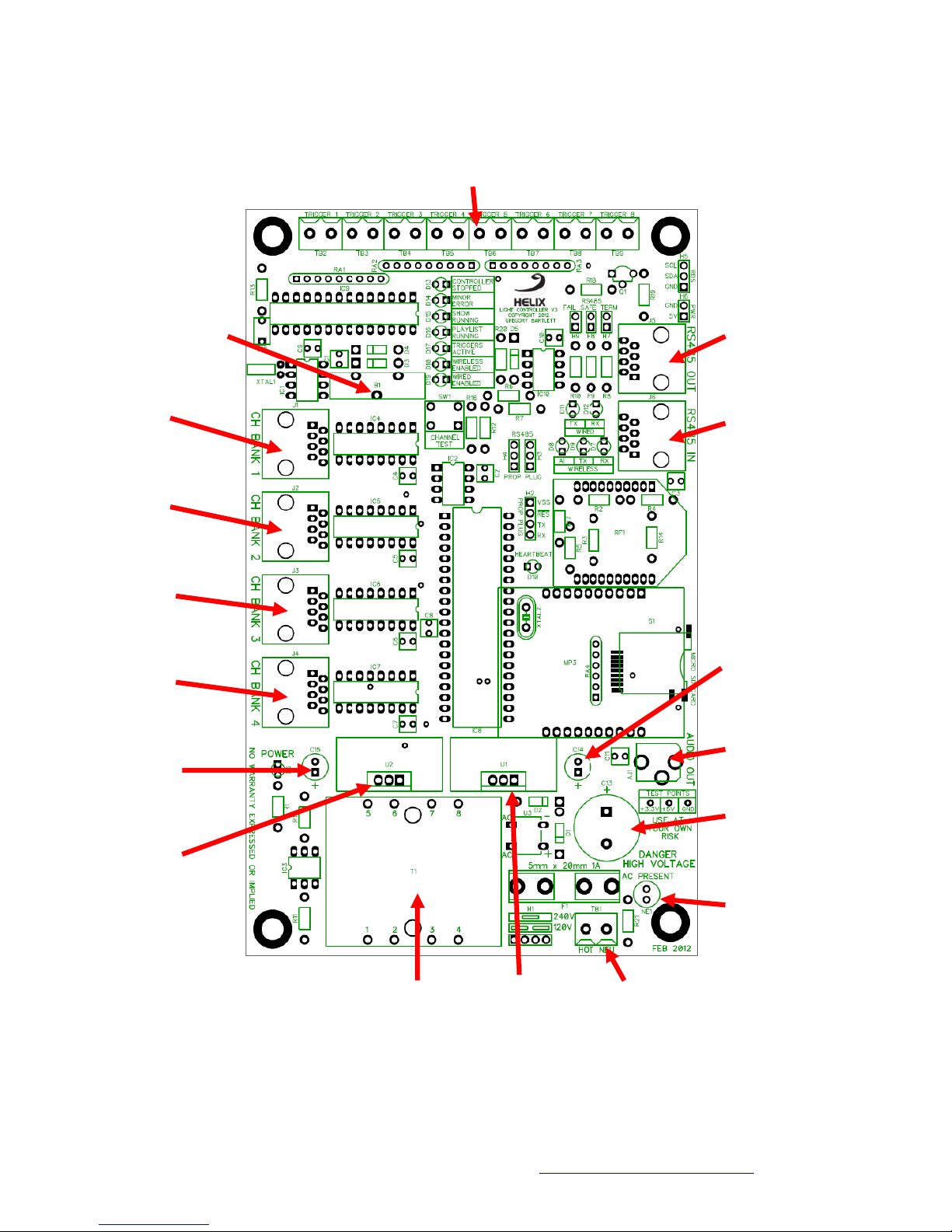
Pictorial Assembly (7 of 7): Remaining Components (Steps 87-110)
88-95 [ ] TB2-TB9*
2p 0.2" Pitch
See Note 14
108 [ ] B1 Socket* 102 [ ] J5
Coin Cell Socket RJ45 Jack
98 [ ] J1 103 [ ] J6
RJ45 Jack RJ45 Jack
99 [ ] J2
RJ45 Jack
100 [ ] J3
RJ 45 Jack
96 [ ] C14
101 [ ] J4 100 F
RJ45 Jack See Note 15
104 [ ] AJ1*
97 [ ] C15 Stereo Audio Jack
100 F
See Note 15 109 [ ] C13
4700 F
107 [ ] U2 See Note 15
3.3V Regulator
See Note 16 105 [ ] NE1
Neon Bulb
110 [ ] T1 106 [ ] U1 87 [ ] TB1
3FD-412 5V Regulator 2p 0.2" Pitch
See Note 17 See Note 16
* These parts are not needed on a Network Node Main Board

Helix Main Board
Assembly and Setup Manual
15
Comments, Questions or Concerns contact the developer at: Greg@helixlightcontroller.com
Assembly Notes
1. The leads on the crystal are very fine, so be careful during installation to make sure they are not twisted or
bent. Insert the leads through the holes in the pads, orientation does not matter. Once it is almost fully
inserted bend the crystal over so that it is laying flush with the board in the area outlined by the solder
mask. Carefully solder the leads in place on the bottom side of the board. See Picture 1 for an example of a
correctly installed RTC crystal.
2. Orientation matters with diodes. The diode has a light band marked on one end; this is the cathode. The
diode needs to be inserted in the PCB with this light band oriented with the band mark on the PCB (the
square pad). See Picture 2 for an example of a correctly installed diode.
3. This crystal needs to be inserted until its base is flush with the PCB and soldered on the bottom side of the
PCB. Orientation of the crystal does not matter. See Picture 3 for an example of a correctly installed crystal.
4. This is a full wave bridge rectifier, orientation matters. Align the markings on top of the chip with the
markings on the PCB. I.e. the pin with "+" inserted in the hole marked "+". Solder on the bottom side of the
PCB.
5. These sockets need to be inserted until they are flush with the PCB. Solder one of the pins. Check to make
sure the socket is flush and perpendicular to the PCB, reheat the pin and reposition as necessary. If the
socket is not perpendicular then the XBee Radio will not plug into them properly. After verifying that the
socket is installed correctly, solder all of the other pins. See Picture 4 for an example of correctly installed
RF1 sockets.
6. Orientation matters with LEDs. The LED has one pin longer than the other; this is the anode. The LED needs
to be inserted in the PCB with the anode lead in the round pad.
7. Orientation matters with bussed SIP resistors. This resistor has multiple resistors connected together by
one of their leads. This is the common lead; it is marked on the package with a dot. The other lead of each
resistor is brought out to a pin on the package. The SIP resistor needs to be oriented on the PCB with the
common lead inserted in the square pad.
8. When installing DIP sockets ensure that the notch in the socket is aligned with the notch on the silkscreen.
Also make sure the sockets are flush with the PCB.
9. Orientation matters with the MOSFET. Carefully bend the leads so they match the layout on the PCB. The
outline of the case needs to match the outline on the silk screen.
10. Carefully break off the appropriate number of pins off of the 40 pin 0.1” pitch strip header (Mouser Part#
517-6111TG). Solder this section on to the PCB with the longer leads facing up. Make sure the header is
perpendicular to the PCB. See Picture 5 for an example of a correctly installed header.
11. Carefully break the 5 pin 0.1” pitch strip header (Mouser Part# 517-929834-01-05-RK) into a two pin and three
pin headers. Solder these headers on to the PCB with the longer leads facing up. Make sure the header is
perpendicular to the PCB. See Picture 5 for an example of a correctly installed header.

Helix Main Board
Assembly and Setup Manual
16
Comments, Questions or Concerns contact the developer at: Greg@helixlightcontroller.com
12. Solder one pin of this 10 pin socket on to the PCB. Make sure the socket is flush and perpendicular with the
PCB, reheating/repositioning it as necessary. If these sockets are not perpendicular to the PCB then the
MP3 player will not properly plug into the PCB. After verifying proper installation then solder all of the
other pins. See Picture 6 for an example of correctly installed MP3 sockets.
13. Orientation matters with the fuse clips. Make sure to install them in the correct orientation so they will
hold the fuse.
14. Connect the eight terminal blocks together by sliding the tab on the side of one into the socket on the side
of the next one. Insert all eight terminal blocks into the PCB and solder from the bottom.
15. This is an electrolytic capacitor, orientation matters. One side of the capacitor is marked as negative. The
pin on this side needs to be inserted in the round pad. Make sure the capacitor is flush with the PCB.
16. This is a TO-220 package voltage regulator, orientation matters. Install this component so that it matches
the silkscreen layout, i.e. the tab is aligned with the smaller rectangle on the silkscreen (closest to the
transformer). The large silkscreen box around this component is the outline for the heat sink. Do not install
the heat sink at this time.
17. Insert the transformer such that the pin numbers on top of the transformer are aligned with the pad
numbers on the PCB. The transformer has small standoff pins. Make sure these standoff pins are flush with
the PCB.

Helix Main Board
Assembly and Setup Manual
17
Comments, Questions or Concerns contact the developer at: Greg@helixlightcontroller.com
Assembly Pictures
Square Pad
Light Band
Picture 1 Picture 2
RTC Crystal Diodes
XBee Sockets
Picture 3 Picture 4
Propeller Crystal XBee Sockets
MP3 Sockets
Picture 5
4 Pin Header
Picture 6
MP3 Sockets
Helix Main Board
Assembly and Setup Manual
18
Comments, Questions or Concerns contact the developer at: Greg@helixlightcontroller.com
Initial Power Up of the Main Board
Before powering up the main board for the first time, perform these checks:
Do NOT install any of the ICs, MP3 Player, XBee radio or the battery for the RTC at this time
Do NOT install the heat sinks on the voltage regulators at this time
Verify that all diodes, LEDs, electrolytic capacitors, voltage regulators, IC sockets are aligned properly
Verify that all components are properly soldered and there are no solder bridges or cold joints
Next perform these steps
1. Install a 1A fuse in the fuse holder F1
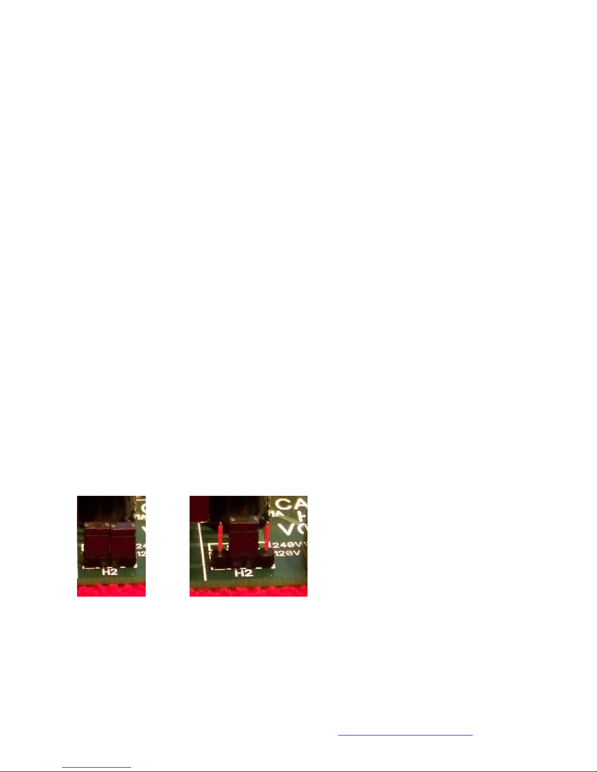
2. Install the shunts (jumpers), Mouser part #151-8010-E, on Header 1 in the correct configuration for your line
voltage. See Picture 7 for 120 VAC and Picture 8 for 240 VAC.
3. Install a power cord on TB1, being careful to properly align the Hot and Neutral leads. The Neutral wire is
the one connected to the wide blade on the plug and is usually white or has ribs or dashes on the wire.
4. Place the main board on a non-conductive surface
5. Plug in the power cord
6. The Power LED (D6) should be illuminated, if not then unplug the power cord and troubleshoot the power
supply section of the board. The Power LED is powered by the 3.3VDC regulator which in turn is powered by
the 5VDC regulator which is connected to the transformer via the full wave rectifier and filter capacitors.
7. With the main board plugged in, carefully touch the heat sink tabs on the two voltage regulators. They
should be cool to the touch or slightly warm at most. If they are hot then you have a short circuit
somewhere on the board. Unplug the board, find the short circuit and repair.
8. With the main board plugged in, use a voltage meter to check the voltage between +5V and GND on the test
points. This voltage should be a solid 5VDC. If it seems to be excessively low or high then unplug the main
board and troubleshoot the 5VDC section of the power supply
9. With the main board plugged in, use a voltage meter to check the voltage between +3.3V and GND on the
test points. This voltage should be a solid 3.3VDC. If it seems to be excessively low or high then unplug the
main board and troubleshoot the 3.3VDC section of the power supply
10. Once the board passes all of these tests then you are finished with the initial testing.
Picture 7 Picture 8
120 VAC 240 VAC
Helix Main Board
Assembly and Setup Manual
19
Comments, Questions or Concerns contact the developer at: Greg@helixlightcontroller.com
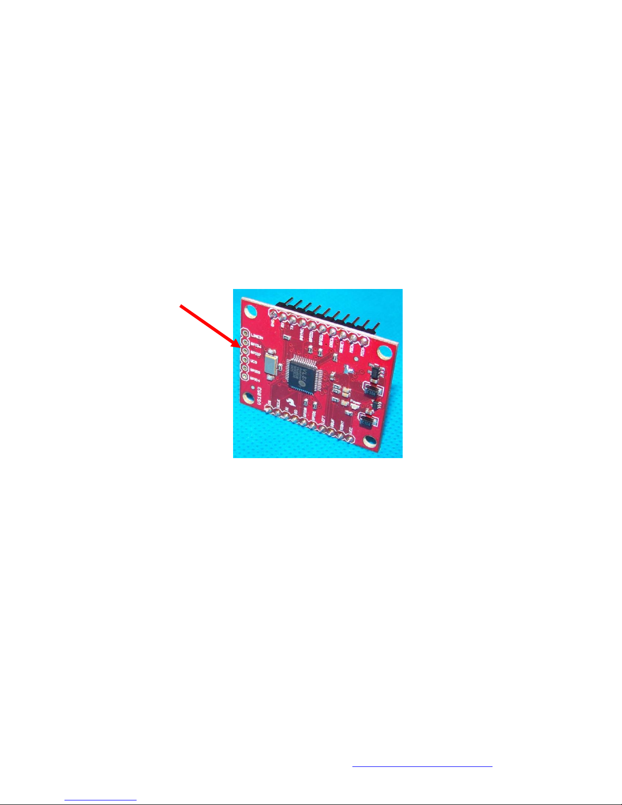
Assembly of the MP3 Board
The MP3 break out board from SparkFun doesn’t have any connector pins installed. In order to be able to connect
this board to the main board these pins must be installed following these steps:
The MP3 board has pads along three sides of the board. There are 10 pads on each of the long sides and six
pads along the bottom. The Helix only uses the two sets of 10 pads. Do not install headers in third set.
Carefully break off two 10 pin headers off of the 40 pin 0.1” pitch strip header (Mouser Part# 517-6111TG).
Insert the shorter pins of one of the 10 pin header through the bottom side of the break out board.
Solder one of the pins in place on the top of the break out board.
Make sure the header is flush with the bottom of the board and perpendicular to the board. Reheat and
reposition the header as necessary.
Solder all of the pins on the header on the top side of the board. See Picture 9 for an example of a correctly
installed header.
Repeat the same steps with the other header.
Do not install a header in these holes
Picture 9
Headers Installed on the MP3 Board
Table of contents
Other HELIX Motherboard manuals


